42 plate heat exchanger diagram
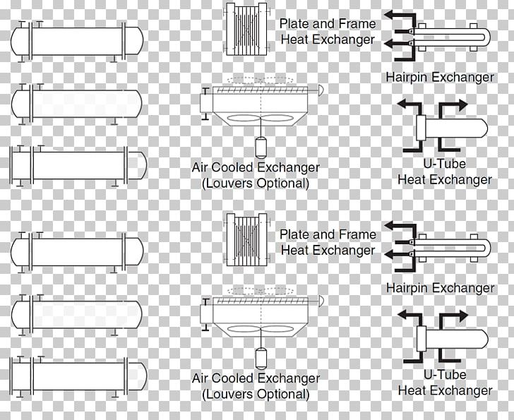
A heat exchanger is a system used to transfer heat between two or more fluids.Heat exchangers are used in both cooling and heating processes. The fluids may be separated by a solid wall to prevent mixing or they may be in direct contact. They are widely used in space heating, refrigeration, air conditioning, power stations, chemical plants, petrochemical plants, petroleum refineries, natural ... Our Process Flow Diagram Symbols (PFD) List will help you better understand the PFD symbology on any engineering project. ... PLATE HEAT EXCHANGER . REBOILER . REBOILER HEAT EXCHANGER . SHELL AND TUBE HEAT 1 . SHELL AND TUBE HEAT 2 . SHELL AND TUBE HEAT 3 . SILENCER . SINGLE PASS HEAT EXCHANGER .
Heat Transfer Solutions Since 1972. New Application? Let’s Get it Done! Xchanger is a leading manufacturer with over 25,000 heat exchangers installed world-wide. Our ten types of heat exchangers are proven, field tested designs, and each heat exchanger is optimized for the particular demands of its specific installation.

Plate heat exchanger diagram
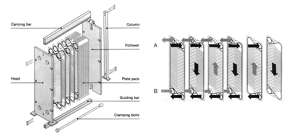
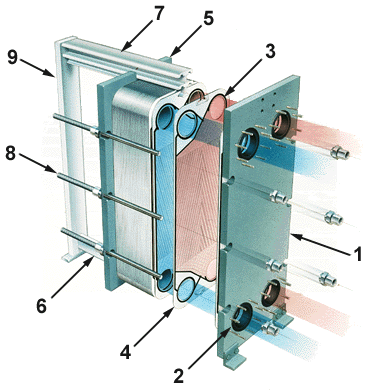
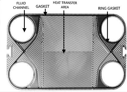
A plate heat exchanger is a type of heat exchanger that uses metal plates to transfer heat between two fluids.This has a major advantage over a conventional heat exchanger in that the fluids are exposed to a much larger surface area because the fluids are spread out over the plates. This facilitates the transfer of heat, and greatly increases the speed of the temperature change. Plate heat exchanger Plate heat exchangers consist of a number of thin corrugated metal plates arranged together. The fluid streams enter the heat exchanger through frame connections and are then distributed to the plates. The two fluid streams pass through alternate spaces formed between the successive plates. Thanks to the HEAT TRANSFER Mechanisms of Heat Transfer: (1) Conduction where Q is the amount of heat, Btu, transferred in time t, h k is the thermal conductivity, Btu/[h ft2 (oF/ft)] A is the area of heat transfer normal to heat flow, ft2 T is the temperature, oF x is the thickness of the conduction path, ft. (2) Convection h is the heat transfer coefficient, Btu/[h ft2oF]. dx ...
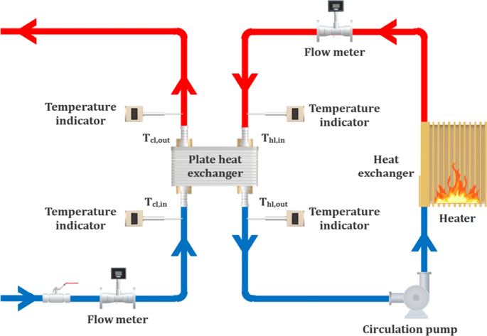
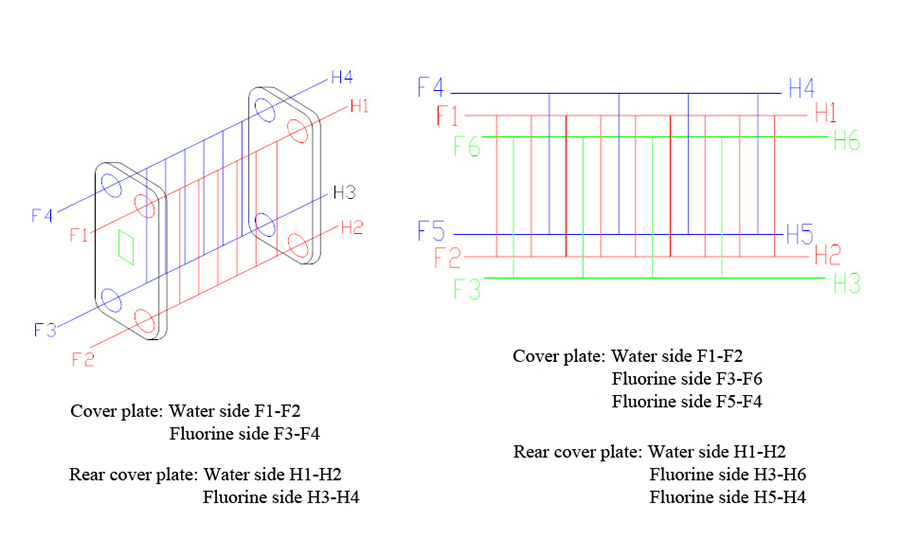
Plate heat exchanger diagram. 03-03-2021 · In this pattern, the heat exchanger has the optimum heat transfer coefficient and can cold or heat the outlets as we desire. Figure 2 illustrates the position of the inlets and outlets. As it is shown in this type, the flows flow in the opposite direction of each other, and at the end in both heads, we have the maximum temperature difference between fluids. 04-05-2021 · Plate/fin heat exchangers have lots of thin metal plates or fins with a large surface area (because that exchanges more heat more quickly); heat exchangers in gas furnaces (gas boilers) work this way. Artwork: A simple example of a plate/fin heat exchanger. This is a cross-flow design with the two fluids flowing past one another at right angles. Raypak Pool & Spa, Residential and Commercial Hydronic Products - Heat Exchanger Design Handbook. Matt Pennington. Download Download PDF. Full PDF Package Download Full PDF Package. This Paper. A short summary of this paper. 19 Full PDFs related to this paper. Read Paper. Download Download PDF.
HEAT TRANSFER Mechanisms of Heat Transfer: (1) Conduction where Q is the amount of heat, Btu, transferred in time t, h k is the thermal conductivity, Btu/[h ft2 (oF/ft)] A is the area of heat transfer normal to heat flow, ft2 T is the temperature, oF x is the thickness of the conduction path, ft. (2) Convection h is the heat transfer coefficient, Btu/[h ft2oF]. dx ... Plate heat exchanger Plate heat exchangers consist of a number of thin corrugated metal plates arranged together. The fluid streams enter the heat exchanger through frame connections and are then distributed to the plates. The two fluid streams pass through alternate spaces formed between the successive plates. Thanks to the A plate heat exchanger is a type of heat exchanger that uses metal plates to transfer heat between two fluids.This has a major advantage over a conventional heat exchanger in that the fluids are exposed to a much larger surface area because the fluids are spread out over the plates. This facilitates the transfer of heat, and greatly increases the speed of the temperature change.
File Plate Heat Exchanger Svg Wikipedia
Modeling And Design Of Plate Heat Exchanger Intechopen

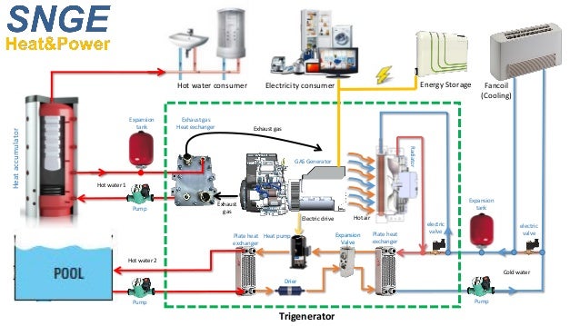
News Tri Hp Project

Plate Type Heat Exchanger Steam Consumption Of Heat Exchangers Download Scientific Diagram

Alfa Laval How Gphes Work

Piping And Instrumentation Diagram Plate Heat Exchanger Process Flow Diagram Compressor Symbol Angle Text Rectangle Png Pngwing
Piping And Instrumentation Diagram Plate Heat Exchanger Process Flow Diagram Compressor Png Clipart Adiabatic Process Angle
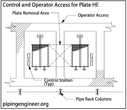
Plate Heat Exchangers Layout The Piping Engineering World

Mechanical Information S Source Plate Heat Exchanger Parts In 2021 Heat Exchanger Refrigeration And Air Conditioning Electrical Diagram

Diagram Of A Typical Plate Heat Exchanger Mcd Plate Heat Trelleborg
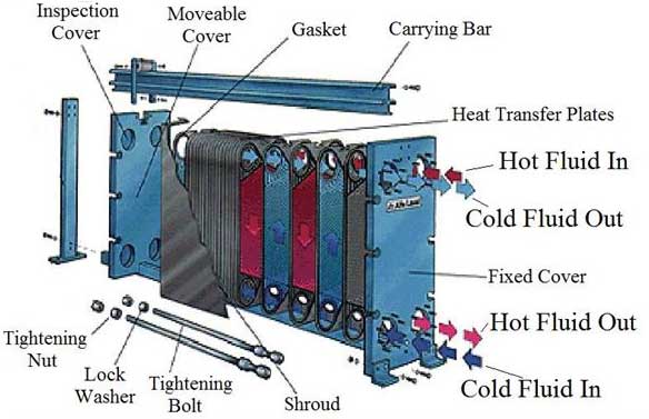
Plate Frame Heat Exchanger Top Manufacturers In China
Usage Diagram 1

Heat Transfer And Pressure Drop Of Ice Slurries In Plate Heat Exchangers Sciencedirect

Instument Midterm Knowing Basic Before Drawing P Id Plate Heat Exchanger Youtube
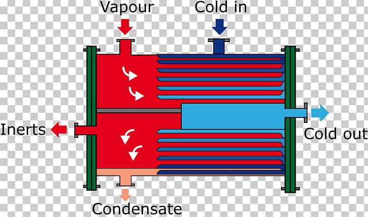
Plate Heat Exchanger Fluid Liquid Vapor Png Clipart Angle Area Countercurrent Exchange Diagram Evaporator Free Png

Schematic Diagram Of The Plate Heat Exchanger 11 Download Scientific Diagram
Daftar Isi Heat Exchanger Aero Engineering

Plate Heat Exchanger Wikiwand
A Comparative Study On Utilizing Hybrid Type Nanofluid In Plate Heat Exchangers With Different Number Of Plates Springerlink
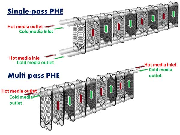
Plate Heat Exchanger Theory Phe Structure And Functional Description
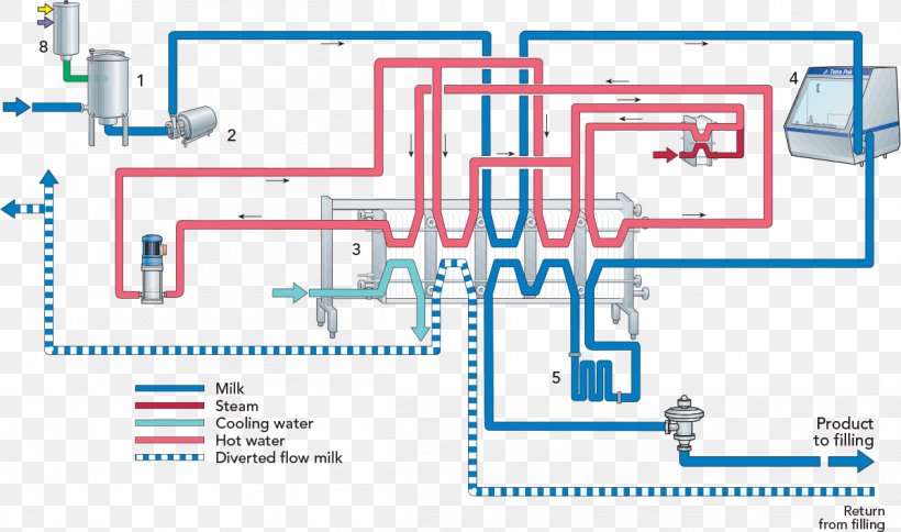
Milk Plate Heat Exchanger Process Flow Diagram Central Heating Png 1199x709px Milk Area Boiler Central Heating

Dynamic Modeling And Control Of A Plate Heat Exchanger Semantic Scholar
Schematic Diagram Of Plate Heat Exchanger Shanghai Dgxt Thermal Technology Co Ltd

Effect Of End Plates On Heat Transfer Of Plate Heat Exchanger Sciencedirect

Thermal Resistance In Corrugated Plate Heat Exchangers Under Crystallization Fouling Of Calcium Sulfate Caso4 Sciencedirect

Heat Exchanger Plate And A Plate Heat Exchanger Diagram Schematic And Image 05

Propellent Plate Heat Exchanger Usage In Dairy Process

Apa Itu Plate Heat Exchanger Phe Prima Handal
Alfa Laval Gasketed Plate And Frame Heat Exchangers
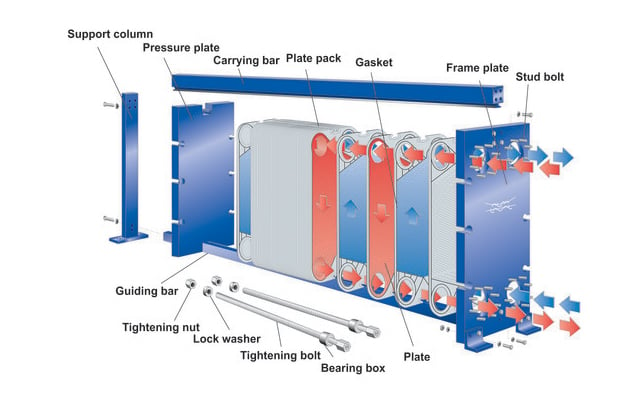
Kontruksi Plate Heat Exchanger Prima Handal

Plate And Frame Heat Exchanger Wiki Mini For Chem Heat Exchanger Refrigeration And Air Conditioning Commercial Hvac
Water To Air Brazed Plate Heat Exchanger 50 60 Plate Ato Com
Water To Air Brazed Plate Heat Exchanger 50 60 Plate Ato Com

Steam Consumption Of Heat Exchangers Spirax Sarco
3

Brazed Plate Heat Exchanger Vitherm Sa
Plate Heat Exchanger Aero Engineering
Simulation And Experimental Analysis Of Heat Transfer Characteristics In The Plate Type Heat Exchangers Using Tio2 Water Nanofluid Emerald Insight
Hisaka Co Jp

Plate Heat Exchanger Applications And Working Principle Hvac Heat Transfer Youtube
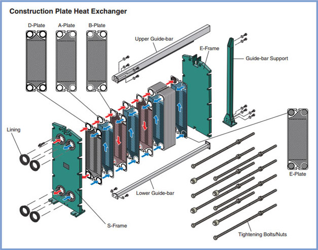
Plate Heat Exchangers Phe Indonesia
1
0 Response to "42 plate heat exchanger diagram"
Post a Comment