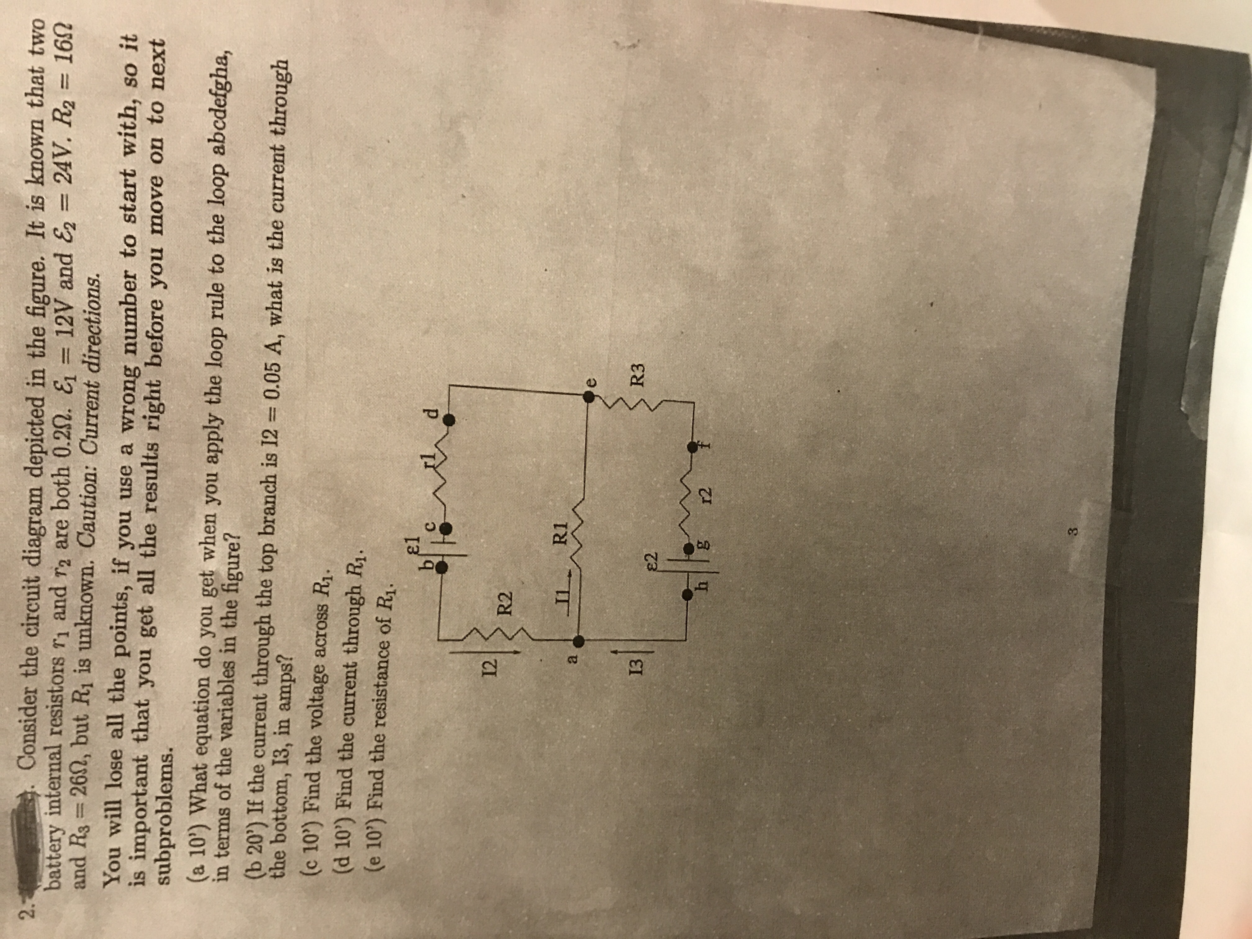
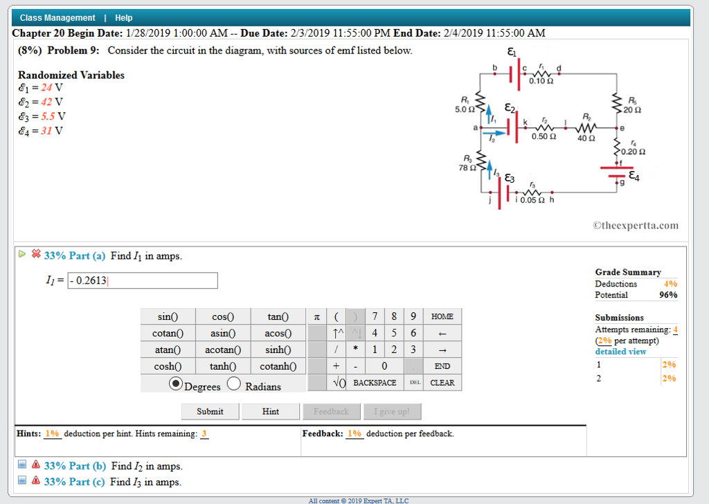
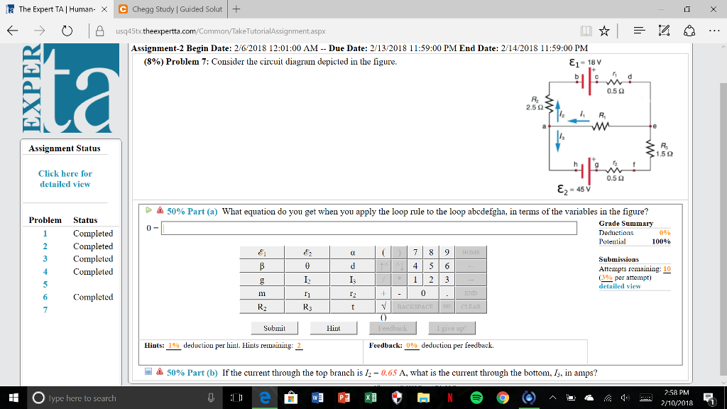
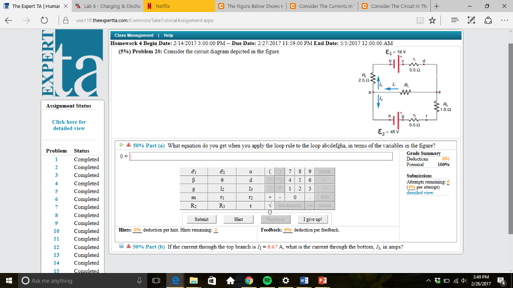
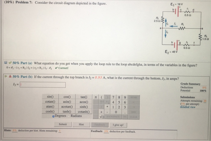
45 consider the circuit diagram depicted in the figure
Finding new neuron subtypes, for example, LNs that cluster with OSNs or neurons that cluster with LNs can be further investigated. Finally, a circuit diagram can be automatically generated using the NeuroGraph Library, as shown in Figure 4f. Lastly, we demonstrate the process of automatic circuit diagram generation of explored brain circuits. The key to this growth has been the ongoing interface circuit enhancements supporting the Tx and Rx ends of the lane. The associated clock generation (and Rx clock recovery) techniques have been at the heart of those circuit innovations as depicted below, showing both embedded clock in data and forwarded clock options.
Consider the circuit shown in Figure P18.9. Find (a) the current in the 20.0-Ω resistor and (b) the potential difference between points a and b. Jan 23 2021 09:25 AM. 1 Approved Answer. Sumeet K answered on January 25, 2021. 5 Ratings ...
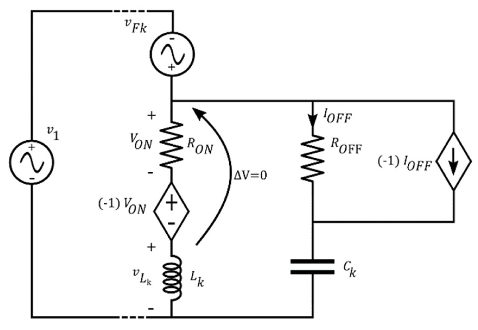
Consider the circuit diagram depicted in the figure
Consider the circuit diagram depicted in the figure. E- Ez. as v Part(a) What equation do you get when you apply the loop rule to the loop abedefgha, in terms of the variables in the figure? Expression : Select from the variables below to write your... Generally, the unknown value is called as R X and of the three known resistances, one resistor (mostly R 3 in the above circuit) is usually a variable Resistor called as R V. Find Unknown Resistance using Balanced Wheatstone Bridge. In the above circuit, let us assume that R 1 is an unknown resistor. So, let us call it R X. As an example, consider the cable sheath's distributed parameter thermal circuit model. The model can be applied to other layers of the power cable. Assuming the thermal capacity of each layer of the cable, the transient thermal circuit model of the power cable (YJV22-6/10 kV −3 × 50) is established, as depicted in Figure 4. Each layer of ...
Consider the circuit diagram depicted in the figure. The proposed QCA layout of the comparator circuit is illustrated in Figure 15. The assembly of the submodules constitutes the greed router architecture (Figure 16). In the block diagram of the proposed architecture, we used two distance calculators and two counters to receive the coordinates of packet destination and neighbor. A battery with e m f, E = 2.00 V and no internal resistance supplies current to the circuit shown in the figure below. When the double-throw switch S is open as shown in the figure, the current in the This paper presents a duty cycle correction scheme based on asynchronous sampling and associated settling analysis. The proposed duty cycle corrector circuit consumes less power and area compared to other corrector circuits due to the low-frequency operation of asynchronous sampling. However, the settling behavior of an asynchronous sampling duty cycle corrector is limited in some operation ... This approach is depicted in in the following diagram (figure 4). While this process minimizes production traffic impact, we still recommend performing this step in a change window. As always, any network changes introduce risk. Figure 4: Adding new 100 Gbps connection without changing traffic patterns . Tune your traffic flow from the cloud to ...
If an LC circuit is considered to be analogous to a harmonically oscillating spring block system, magnetic energy analogous to kinetic energy and electrical energy analogous to potential energy. Ques. At the moment depicted in the LC circuit, the current is non-zero and the capacitor plates are charged as shown in the figure below. The circuit diagram of a summing amplifier is as shown in the following figure. Figure 5. Op-amp as Adder. Differential Amplifier Differential amplifier is an analog circuit with two inputs and and one output in which the output is ideally proportional to the difference between the two voltages. Please solve for both methods and give all the answers. I will be appreciated. Draw reactance diagram as well. Thank You so much in advance . 1. Refer to the Single Line diagram Shown below mi TI 0 L13 T2 L12 138KV C2H M L23 4 3 ارا Tg z 63 - Determine the magnitude of a 3 phase fault, and a single line to ground fault on Bus 2. In amper That reminds me of a story. ♫ “And the D-I-Y rocket’s red glare… The homebrew bombs exploding in air… Our vodka 150^o proof through the night…That we somehow still had our hair…”♫ *The Fourth of July!* Or, as we veteran pyrotechnicians call it: “Amateur Night”. However, before we display our prowess afore these once-a-year pyro-tyros, we need to turn back the clock a few months, because, to quote a sage philosopher of the day: “What a long strange trip it’s been.” Moreover, we need a lit...
Let us consider an RLC circuit as depicted in Figure 4.1.1 in which we have an initial current, \(I(0) = 3.2\) amps with a resistance of \(R = 7\) ohms, an inductance of \(L = 1\) henry, and a capacitance of \(C = 0.1\) farads. Since we have some current in the circuit already \(I(0) = 3.2\) at the start we shall not need an inducing \(E(t ... #This glossary is outdated. Please use [the one hosted here](https://immortalmountain.wordpress.com/glossary/wuxia-xianxia-xuanhuan-terms/) instead! Thank you. *** *** ##Novel Categories **Wuxia** ( 武俠 wǔxiá ) - literally means "Martial Heroes". Fictional stories about regular humans who can achieve supernatural fighting ability through Chinese martial arts training and internal energy cultivation. Themes of chivalry, tragedy, revenge & romance are common. **Xianxia** ( 仙侠 xiānxiá ) - ... The resistance temperature properties of PTC are shown in the diagram above. When there is an overcurrent, the PTC heats up, and the temperature quickly rises. The PTC's impedance rises quickly, generating an open circuit. The current declines after the open circuit, the heating drops, the temperature drops, and the PTC returns to low impedance. The house on Bald Mountain was less than a half-hour's drive from that bout of pandemonium. They took the turn off onto an old fire trail that led higher up the mountain. James and Martin had a panoramic view of the private homes separated by acres of land between them. The house was large and set half a mile back from the main road leading to the rest of the homes. The driveway was a slow curve of gravel that meandered up to the house. They approached from the woods, each man from a different ...

Applied Sciences Free Full Text Parametric Pspice Circuit Of Energy Saving Lamp Emulating Current Waveform Html
*Disclaimer: I am not a financial advisor. This entire post represents my personal views and opinions, and should not be taken as financial advice (or advice of any kind whatsoever). I encourage you to do your own research, take anything I write with a grain of salt, and hold me accountable for any mistakes you may catch. Also, full disclosure, I hold a net long position in GME, but my cost basis is very low, and I'm using money I can absolutely lose. My capital at risk and tolerance for risk ge...

Consider The Circuit Diagram Depicted In The Figure A What Equation Do You Get When You Apply The Loop Rule To The Abcdefgha In Terms Of The Variables In The Figure B
Figure 1. Circuit diagram of NMOS dynamic comparator Figure 2. Transient analysis of NMOS dynamic comparator based on di erential inputs. Strong ARM latch based dynamic comparator is used to compare both the designs. NMOS and PMOS driving comparator circuit is depicted in gure 1 and gure 3, respectively.
In June 2007 the "Chad Drone" story broke and boy was it a doozy. The photos and graphic design work involved in this UFO story is just mind-boggling. Still way better than anything that has come along since. Check out the link as all the elements of this incredible story are still on this particular site. If nothing else, the folks who designed the PACL Linguistic Primer deserve some kind of award for creativity, detail and just plain weirdness. [http://droneteam.com/isaaccaret.fortunecity.c...
Consider an ac circuit consisting of a capacitor connected to an ac source. Let the instantaneous value of emf be V = V m sin ωt …(1). Let V C be the instantaneous voltage drop across the capacitor, then by Kirchoff's loop rule, V - V C = 0 V = V C = V m Sin ωt …(2). But from the definition of capacitance, V C = Q / C or Q= V C C. Substituting for Vc we have Q = C V m sin ωt …(3)
A schematic diagram of the overall structure is shown in Figure 1b. Their transmittance spectra are depicted in Figure 2 c. They have the same structure parameter setting, which is as follows: L = 500 nm, H = 350 nm, l = 250 nm, d = 353 nm, φ = 60°, g = 10 nm, h = 140 nm.
Figure 2 shows a schematic representation of an IMPATT diode reverse-biased into avalanche breakdown.As in any reversed-biased pn junction, a depletion zone forms in the n-type region of the diode; its width depends on the applied reverse voltage. The depletion zone acts as a nonlinear capacitor if V dc is less than V b.This property is utilized in varactor diodes. the saturation current ...
Consider the above figure in which R1, R2, R3, are connected between common points A & B across supply voltage of V volts. In parallel combination, the potential difference across all resistances is the same (i.e. V volts), current in each resistor is different and is given by ohm's law and the total current (I) through the combination is the ...
5-a) An RL circuit is driven by an AC voltage source as shown in the figure. (Figure 1). On the phasor diagram below, adjust the phasor that represents the voltage across the resistor (VRVRV_R) at the instant indicated to the proper orientation.
A general schematic model for such conversion is depicted in the below-given figure: To design the combinational circuit, we require a Boolean expression which is obtained using the excitation table of both given flip-flop and required flip-flop. The Boolean expressions are obtained by solving the K-Map drawn for the inputs and outputs of a ...
#Rough Draft - (Glossary of Terms in Wuxia, Xianxia & Xuanhuan Novels)? work on title maybe *** ##Novel Categories **Wuxia** ( 武俠 wǔxiá ) - literally means "Martial Heroes". Fictional stories about regular humans who can achieve supernatural fighting ability through Chinese martial arts training and internal energy cultivation. Themes of chivalry, tragedy, revenge & romance are common. **Xianxia** ( 仙侠 xiānxiá ) - literally means "Immortal Heroes". Fictional stories featuring magi...
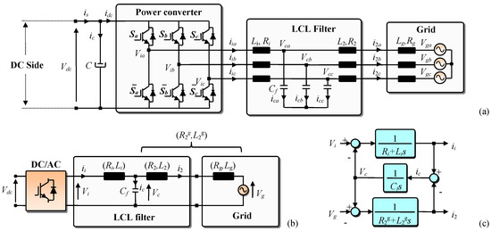
Energies Free Full Text An Improved Lcl Filter Design In Order To Ensure Stability Without Damping And Despite Large Grid Impedance Variations Html
Figure 3. PGIA bridge interface with four gain settings . Figure 4 shows a simplified diagram of the PGIA to demonstrate how different taps of the resistor ladder, implemented by analog switches (eight total) shorted two at a time to set the gain, configure the circuit.

10 Problem 1 Consider The Circuit Diagram Depicted In The Figure Docx 10 Problem 1 Consider The Circuit Diagram Depicted In The Figure 1 592 Course Hero
“We started to think more about doing a mind-bender in a long format. We thought, What if you actually took the time to develop what’s at the center of the labyrinth, even if you never get there? We spent a year and a half just making all of this stuff up, doing the mathematics and the story. This first season is the outermost ring of that labyrinth.” --Brit Marling https://www.vulture.com/2017/01/brit-marling-the-oa.html https://imgur.com/a/GwUT56x (In Greek mythology, the Labyrinth (Ancient ...

Exergy Study Of Amine Regeneration Unit Using Diethanolamine In A Refinery Plant A Real Start Up Plant Sciencedirect
With the release of Rhythm of War coming up fast I thought now would be a good time to post all my musings and theories on the nature of the Cosmere and the underlying theory of Sanderson’s magic systems. I had originally been planning for this to be done in several parts with many more quotes to the text and citations of WOBs, but unfortunately life has meant I don’t have the time to be as rigorous as I’d like. With that in mind here’s a layout of the structure of my post. Hopefully my reason...
Single-line diagram and inverter power circuit. The single-line diagram of a typical three-phase PV grid integration system is illustrated in Fig. 1.In this system, all PV arrays (considered as one of the DERs) are connected to a common DC bus of 600 V through the individual MPPT tracking units and suitable DC-DC converters incorporated with each PV array.
The circuit diagram of the measuring device is shown on Fig. 4c. It is designed for amplifying the small differences measured by IC1 and IC2 and also to compensate their manufacturing differences.
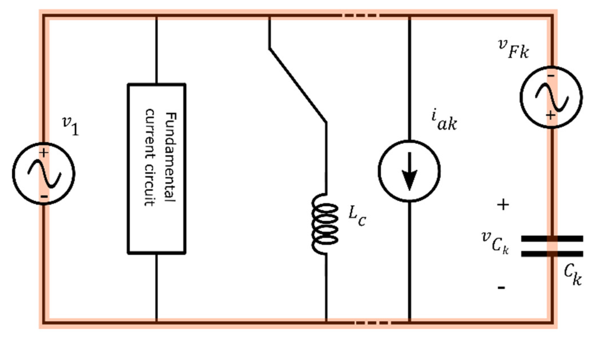
Applied Sciences Free Full Text Parametric Pspice Circuit Of Energy Saving Lamp Emulating Current Waveform Html
[Back to PART 5.2](https://old.reddit.com/r/JFKeveryday/comments/jz86gt/small_wounds_in_the_front_of_jfks_head_part_52/) [Back to CONTENTS](https://old.reddit.com/r/JFKeveryday/comments/jzcmqa/small_wounds_in_the_front_of_jfks_head_contents/) In 2003, Dennis David appeared on [Black Op Radio, part 121](https://drive.google.com/drive/folders/1yPw6CcNrXCZaKA-8cPWTGM-FcRsWJLyf?usp=sharing): >James Fetzer: Did you see Pitzer then? >Dennis David: No. I did not see Bill Pitzer that night. ...
We were hiding in Rennie’s garage under the exposed glare of uncovered light bulbs. Hannah and I weren’t concerned with being caught. There were few neighbours here on the edge of new residential developments like Riverwood (although more than I expected given recent events). Besides, with the early spring windstorm screaming outside, it’s doubtful we’d be heard over the gale-force winds even should someone wander by. Every time a heavy gust from the Rockies leaned on the little prairie house, ...
The proposed control system for street lighting with HPS lamps employs a client-server architecture comprised of four major components, as illustrated in Figure 2.The communication protocol between each component was designed using the system flow diagram depicted in Figure 3.The actuator layer contains a microcontroller module for controlling the lamps, and a wireless communication module for ...
TCP 3-way handshake or three-way handshake or TCP 3-way handshake is a process which is used in a TCP/IP network to make a connection between server and client. Syn use to initiate and establish a connection. ACK helps to confirm to the other side that it has received the SYN.
Consider the following circuit in the Figure: 36 Fig. 3: Circuit Diagram of Operational Amplifier without Feedback When you power on the above circuit, the LED will be glowing irrespective of the voltage you are applying at the non-inverting pin through the variable resistor.
Light switch wiring diagram depicted here shows the power from the circuit breaker panel going to a wall switch and then continues to a ceiling light with a three conductor cable. From the ceiling box an electrical receptacle outlet is fed power. The diagram above shows a two conductor cable from the circuit breaker panel going to a wall switch.
As an example, consider the cable sheath's distributed parameter thermal circuit model. The model can be applied to other layers of the power cable. Assuming the thermal capacity of each layer of the cable, the transient thermal circuit model of the power cable (YJV22-6/10 kV −3 × 50) is established, as depicted in Figure 4. Each layer of ...
Generally, the unknown value is called as R X and of the three known resistances, one resistor (mostly R 3 in the above circuit) is usually a variable Resistor called as R V. Find Unknown Resistance using Balanced Wheatstone Bridge. In the above circuit, let us assume that R 1 is an unknown resistor. So, let us call it R X.
Consider the circuit diagram depicted in the figure. E- Ez. as v Part(a) What equation do you get when you apply the loop rule to the loop abedefgha, in terms of the variables in the figure? Expression : Select from the variables below to write your...

Chemoresistive Materials For Electronic Nose Progress Perspectives And Challenges Park 2019 Infomat Wiley Online Library

10 Problem 1 Consider The Circuit Diagram Depicted In The Figure Docx 10 Problem 1 Consider The Circuit Diagram Depicted In The Figure 1 592 Course Hero

Modeling Design And Control Of A Modified Flyback Converter With Ability Of Right Half Plane Zero Alleviation In Continuous Conduction Mode Sciencedirect

10 Problem 1 Consider The Circuit Diagram Depicted In The Figure Docx 10 Problem 1 Consider The Circuit Diagram Depicted In The Figure 1 592 Course Hero

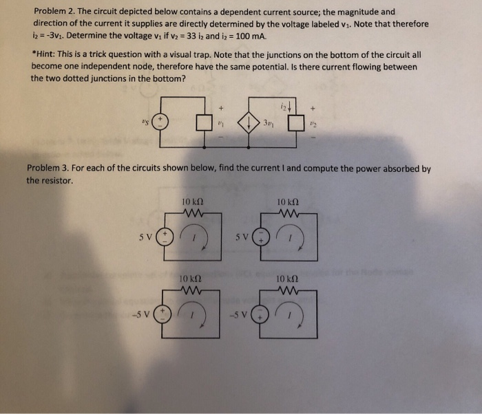















0 Response to "45 consider the circuit diagram depicted in the figure"
Post a Comment