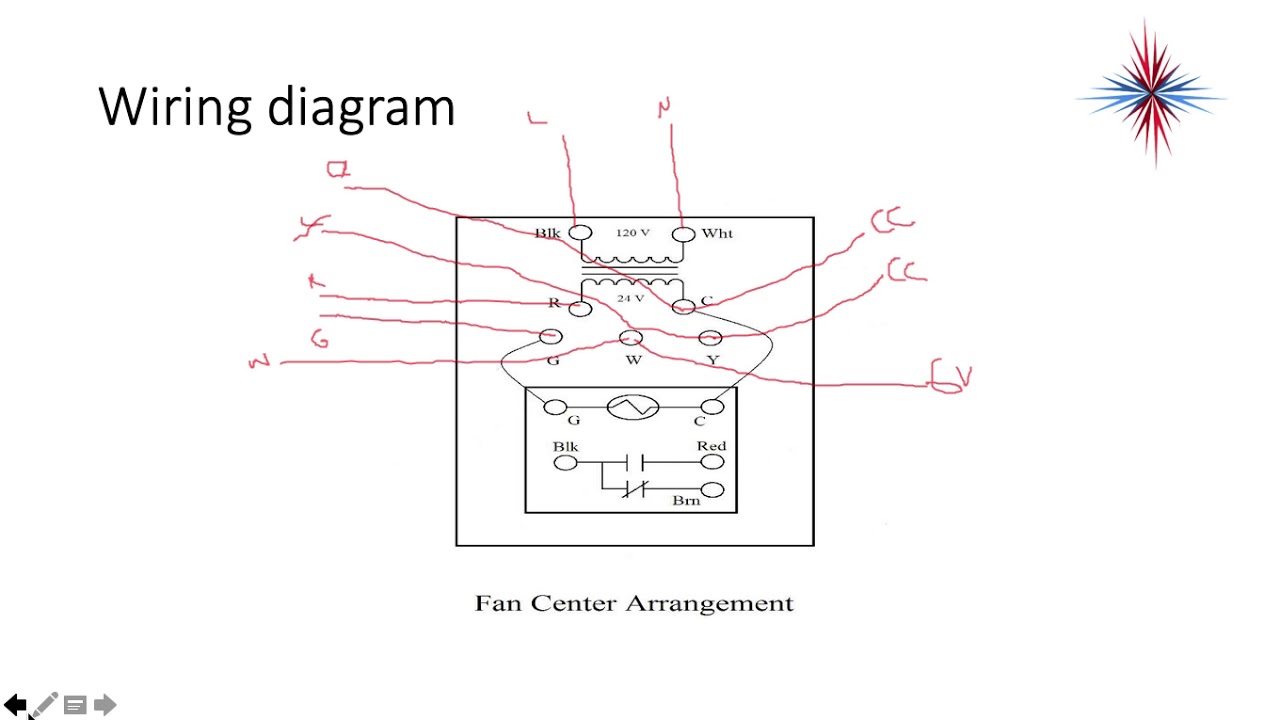
45 fan center wiring diagram
This video is about The fan center is used on furnaces to turn on the fan without the heat or if air conditioning. This video is part of the heating and co... Bookmark File PDF Honeywell Fan Center Wiring Diagram available in the ebook version. 1927. Italië is in de greep van de fascistische dictator Mussolini. De broers Luca en Berio werken als trapezewerkers in een klein, rondreizend circus. Ze verloren hun moeder in de oorlog en wonen nu bij goochelaar Veronica. Dan komt de jonge fotografe
1 Nc 24 V Coil White Rodgers 90 380 Replacement Heavy Duty Switching Fan Relay Spst No Tools Home Improvement Building Supplies. White Rodgers 90 112 Fan Control Center. 87a Relay Wiring Diagram Hawaiianpaperparty. Fan Relay Getting Hot Diy Home Improvement Forum. 90 360 White Rodgers Fan Relay Type 184 24 Vac Coil 50 60 Hz Spno Data 77 Ohms Dc ...

Fan center wiring diagram
White Rodgers - Fan Control Center, VAC Primary 24 VAC Secondary, SPDT Relay - Transformer and Relay Combination for Easy Installation on a. I'm replacing a White Rodgers Fan Control on my furnace. The original heater diagram shows one side black v but I can't figure where Black from relay goes where the black for transformer goes 3 wires in ... I have no wiring diagram for this unit but the M# is G76-7502 C2-5. I need help wiring the fan control center and the fan limit switch to power. I bought a new White Rodgers Fan Control Center but am not sure which wires go where. The fan control has 2 black wires coming out of the switch in the back that is normally open. And 2 red wires from a Fan Control Center Wiring [ 5 Answers ] I'm trying to make this old Magic Chef furnace work in my garage. I got it and the Fan Control Center was broken, laying inside unwired. I have no wiring diagram for this unit but the M# is G76-7502 C2-5. I need help wiring the fan control center and the fan limit switch to power. I bought a new...
Fan center wiring diagram. File Type PDF Honeywell Fan Center Wiring Diagram Distribution Systems The second edition of Extrusion is designed to aid operators, engineers, and managers in extrusion processing in quickly answering practical day-to-day questions. The first part of the book provides the fundamental principles, The ICM Fan Control Center is a solid.A wiring diagram is a simple visual representation of the physical connections and physical layout of an electrical system or circuit. It shows how the electrical wires are interconnected and can also show where fixtures and components may be connected to the system. Carrier Wiring Diagrams Pdf - Starting ... Sep 10, 2021 · Fan control center wiring diagram what is a wiring diagram. Fan control center wiring diagram just what s wiring diagram. 60 Lovely Mini Cooper Cooling Fan Wiring Diagram In 2020 Cooling Fan House Wiring Mini Cooper . A wiring diagram is a type of schematic which makes use of abstract photographic signs to show all the interconnections of components in a system. Fan control center wiring diagram. Symbols that stand for the parts in the circuit and lines that. Jul 11, 2018 · Imperial Electric Fan Wiring Diagram Fan center wiring diagram for furnace schematic 94a fan center wiring diagram library help my ecobe3 out perform 20 t stat hvac diy chatroom honeywell fan center wiring diagram schematic. Whats people lookup in this blog: How To Wire A Fan Center Relay
90 113 White Rodgers Fan Control Center Arnold S Service Company Inc. Adding fan control center limit furnace wiring diagram full proper diy for older furnaces orion s photos portrait mechanical ecobe3 out perform my 20 t stat resideo relay transformer heat exchanger in only to stopped working after a burning smell white rodgers s84 17 incubator 3 backyard ens any hvac gurus on here looking 90 ... hvacdave84 : So, line voltage (black) would attach to the BLACK wire (the one with the red and brown wires) on the control center. that will feed the relay the voltage it needs to pass to operate the fan. the wire coming FROM the fan/limit is going to be the wire that brings 120V to it. it would attach to the BROWN wire on the control you're wiring. since that is the normally closed contact on ... Nov 30, 2017 · 90 370 White Rodgers Fan Relay Arnold S Service Co Inc. Fan Center For Older Furnaces. Diagram Wiring Fan Relay Switch Full Version Hd Quality. Fan control center relay amp honeywell wiring oil fired furnace wire limit switch 90 113 white rodgers emerson transformer s84 17 diagram hvac diagrams any gurus on here looking for 2000 2 5rs full ... White Rodgers Fan Center Wiring Diagram - wiring diagram is a simplified satisfactory pictorial representation of an electrical circuit. It shows the components of the circuit as simplified shapes, and the faculty and signal associates with the devices. A wiring diagram usually gives information very nearly the relative direction and union of ...
HONEYWELL L4064T INSTRUCTIONS [PDF] (ca 1970) wiring diagram shown below thanks to reader Haydn Chambers, used an extra set of spade terminals in the center of the control - these were connected to low-voltage terminals that provided a fan-timer heater function such as shown in the illustration that includes a low-voltage (24VAC) gas valve and ... From the thousands of photos online about honeywell fan center wiring diagram, we selects the top choices with greatest resolution exclusively for you all, and now this images is one of pictures choices in this greatest graphics gallery regarding Honeywell Fan Center Wiring Diagram.I hope you will enjoy it. This kind of graphic (R8285D-C5 with Honeywell Fan Center Wiring Diagram) above will be ... Jun 19, 2018 · fan control center wiring diagram – What is a Wiring Diagram? A wiring diagram is a straightforward visual representation from the physical connections and physical layout of your electrical system or circuit. It shows how the electrical wires are interconnected and can also show where fixtures and components might be coupled to the system. Honeywell fan control center wiring diagram full hd version mary changezvotrevie fr white rodgers wiring diagram advanced american deluxe stratocaster for begeboy source r8285a1048 honeywell fan center relay transformer spdt 120v amre supply 40 va fan center w spdt switch action 40 va fan center w spdt switch action.
A C Stopped Working After A Burning Smell Doityourself Com Community Forums
Fan Control Center Wiring Diagram Collection. fan control center wiring diagram - Just What's Wiring Diagram? A wiring diagram is a type of schematic which makes use of abstract photographic signs to show all the interconnections of components in a system. Electrical wiring representations are made up of 2 points: symbols that stand for the parts…

Electrical Relay Wiring Electric Fan Electricity Relay
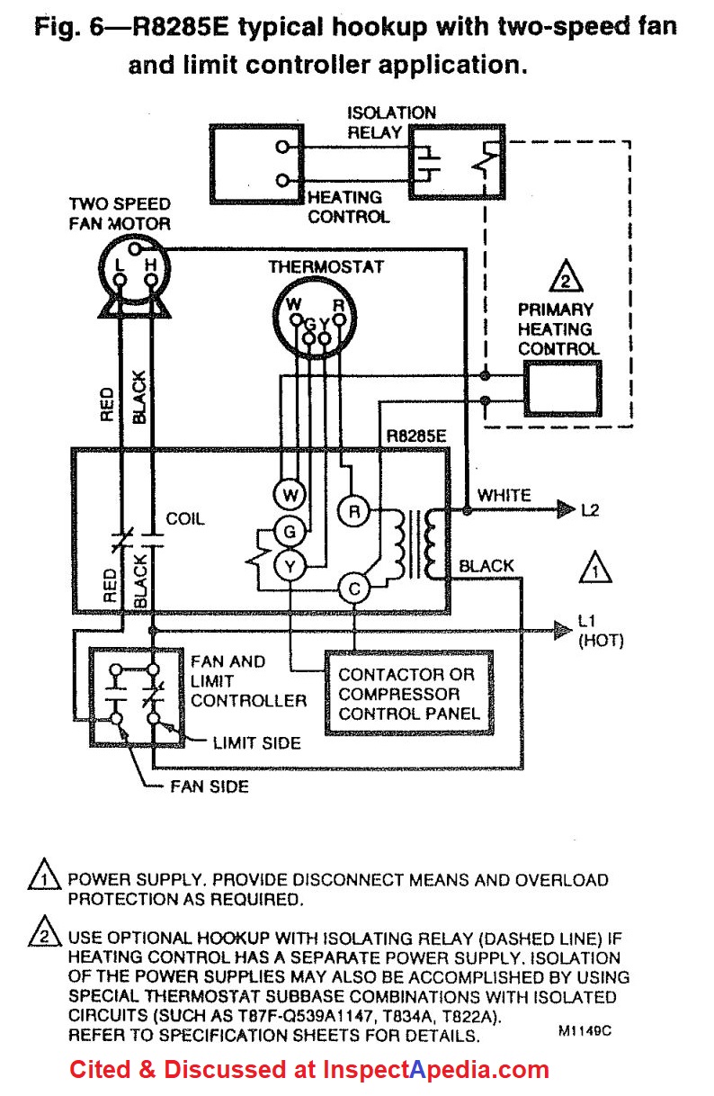
of line voltage fan motors and auxiliary circuits in heating, cooling, or air conditioning systems. For model specifica-tions, refer to Table 1. TABLE 1—R8285 MODEL SPECIFICATIONS. Control Replacement Contact Rating See Wiring Center Relay AFL ALR Switching Input Voltage (Vac) Diagram R8285A R8222B 12 60 spdt 120 or 208/240 Fig. 1
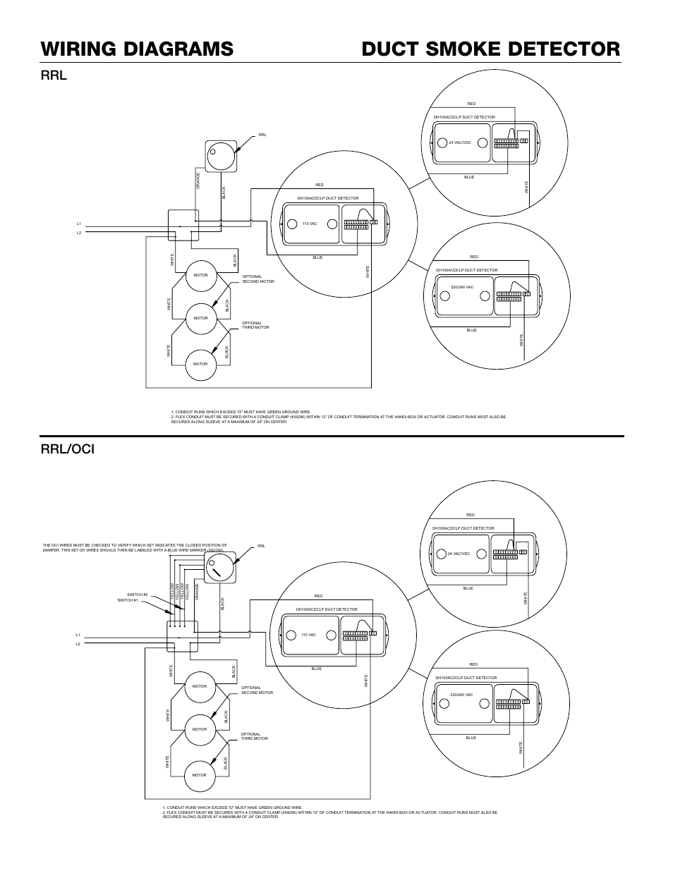
Duct Smoke Detector Wiring Diagrams Rrl Rrl Oci Greenheck Fan Dh100acdclp User Manual Page 5 8 Original Mode
Honeywell Fan Center Wiring Diagram inside Honeywell Fan Limit Switch Wiring Diagram by admin Through the thousand pictures on the net regarding honeywell fan limit switch wiring diagram, we all choices the best collections together with ideal resolution just for you, and this images is usually one of graphics collections inside our very best photographs gallery in relation to Honeywell Fan ...

Cleanair Stat
White Rodgers Fan Control Center Wiring Diagram - One of the most difficult automotive repair tasks that a mechanic or repair shop can bow to is the wiring, or rewiring of a car's electrical system.The problem in fact is that every car is different. bearing in mind irritating to remove, replace or repair the wiring in an automobile, having an accurate and detailed white rodgers fan control ...

Honeywell R8285d5001 50va Fan Center Transformer Relay W Dpst Switch Action Hvac Parts Other Hvac Parts
Description : R8285D-C4 pertaining to Honeywell Fan Center Wiring Diagram, image size 400 X 400 px. Honestly, we also have been remarked that honeywell fan center wiring diagram is being just about the most popular field at this moment. So we attempted to identify some terrific honeywell fan center wiring diagram graphic to suit your needs.
Wiring Fan Control Relay Diy Home Improvement Forum
Healthy Home System Control Plus. Control circuits for hvac systems diagram fan relay full furnace limit switch ac wiring hvacquick how to s 1 generic 120v coil from com rib relays bathroom fans diagrams and troubleshooting hyundai radiator understanding with the 90 340 a cause transformer adding center factory air conditioning schematic grainger supply condenser healthy home system plus er ...

Honeywell Fan Centers R8239a H At72h J Q633a User Guide Wiring Diagram Manuals
Honeywell Fan Center Wiring Diagram - wiring diagram is a simplified usual pictorial representation of an electrical circuit. It shows the components of the circuit as simplified shapes, and the capability and signal connections between the devices. A wiring diagram usually gives recommendation nearly the relative tilt and union of devices ...
Help Replacing Line Voltage Dehumidistat With Honeywell Trueiaq Digital Control Diy Home Improvement Forum
existing relay. Also record all external wiring connections (line and low voltage). Use the color-coded terminal leads installed on the new fan control center to duplicate the wiring of the existing control. Make sure all connecting points are the same for both relays. Lead wires connecting the low voltage relay coil to terminals

A C Stopped Working After A Burning Smell Doityourself Com Community Forums
Oct 22, 2018 · Diagram Fan Center Relay Wiring Full Version Hd Quality Develop 2 Jftechnology It. Honeywell Fan Center Control Wiring Diagram Volvo D6d Code 03 Honda Accordd Waystar Fr. Fan Control Center Wiring Diagram Corsa Wiper Motor Begeboy Source. Fan Control Center Relay Transformer 90 112 Thru 130 Manualzz.

35 Unique Maxess Fan Wiring Diagram Ceiling Fan Switch Stand Fan Table Fan
Wire relay Com and Relay N.O. (of the fan center) parallel to your fan limit. So your diagram Black goes to relay Com wire and Blue goes to the relay N.O. (Normally open) wire. Wire Transformer black to the hot black wire in your drawn diagram. Wire tranformer white to furnace Neutral. On the low voltage side... Fan center R connects to Nest Rc.

New Dual Electric Radiator Fan Wiring Diagram Electric Radiator Fan Radiator Fan Electric Radiators
02.10.2018 02.10.2018 4 Comments on White Rodgers 90 113 Wiring Diagram I'm replacing a White Rodgers Fan Control on my furnace. The original heater diagram shows one side black v but I can't figure where Black from relay goes where the black for transformer goes 3 wires in that.
How Do I Wire This 240v Fan Motor And Thermostat Home Improvement Stack Exchange
Below is a excellent picture for honeywell fan center wiring diagramweb.net have been looking for this picture throughout internet and it came from trustworthy resource. awesome cooling fan circuit diagram wiring control center relay and transformer honeywell ra emerson 90 ,fan control center 90 mars wiring diagram u model,honeywell ra fan ...
India Accurascan Com
Fan Control Center Wiring [ 5 Answers ] I'm trying to make this old Magic Chef furnace work in my garage. I got it and the Fan Control Center was broken, laying inside unwired. I have no wiring diagram for this unit but the M# is G76-7502 C2-5. I need help wiring the fan control center and the fan limit switch to power. I bought a new...

Toyota Land Cruiser Prado Toyota Hilux Toyota Corolla Car Land Cruiser Prado Angle Text Electrical Wires Cable Png Pngwing
I have no wiring diagram for this unit but the M# is G76-7502 C2-5. I need help wiring the fan control center and the fan limit switch to power. I bought a new White Rodgers Fan Control Center but am not sure which wires go where. The fan control has 2 black wires coming out of the switch in the back that is normally open. And 2 red wires from a
Electricalforgas Fan Centers Youtube
White Rodgers - Fan Control Center, VAC Primary 24 VAC Secondary, SPDT Relay - Transformer and Relay Combination for Easy Installation on a. I'm replacing a White Rodgers Fan Control on my furnace. The original heater diagram shows one side black v but I can't figure where Black from relay goes where the black for transformer goes 3 wires in ...

Wiring Schematic Diagram 1997 Audi A4 Air Conditioning System Circuit And Schematic Diagram On 1997 Audi A4

90 113 White Rodgers Fan Control Center Arnold S Service Company Inc
Kitchen Fan Control Center 475870 Iom Manualzz

Smart Bus Hvac2 Air Condition Control Module G4 Sb Hvac2 Dn
Honeywell L4064b Combination Fan And Limit Control How To Set The Temperatures And Limits On The Furnace Fan Limit Switch Control
Cmb Bxi Sl Fans Car Mon Manualzz

Part 2 Help Installing Nest On Millivolt System Using 24v Transformer Doityourself Com Community Forums

Need Help With Wiring In A Pilot Relite To Fan Control Center Doityourself Com Community Forums
Mercedes Ml320 W163 Wiring Diagrams Car Electrical Wiring Diagram

Adding Fan Control Center Doityourself Com Community Forums
Suneducationgroup Com 24 Volt 24010 New Mars Universal 40va Fan Control Center Relay 120 208 240 Home Furniture Diy Home Garden

Need Help With Wiring Diagram For A 2 Thermostat 2 Zone Valve With One Pump Doityourself Com Community Forums

Help With Ecobee4 To Line Voltage Using Fan Control Center 90 113 Doityourself Com Community Forums

18 Electric Stand Fan Wiring Diagram Wiring Diagram Wiringg Net Stand Fan Diagram Electricity

Cooling Fan Mazda 6 I Sport 2008 System Wiring Diagrams Autok Bekotesi Rajzai

Fan Center Control Wiring Auto Electrical Wiring Diagram
My Incubator 3 Backyard Chickens Learn How To Raise Chickens

I M Trying To Replace My Fan Control Center White Rodgers S84 17 With Its Replacement White Rogers 90 112 The Wires
Ecobee Help Dual Thermostat Wiring Diagram For Powering From Boiler If Power Goes Out R Ecobee

Electric Fan On A 1974 Triumph Tr6
2
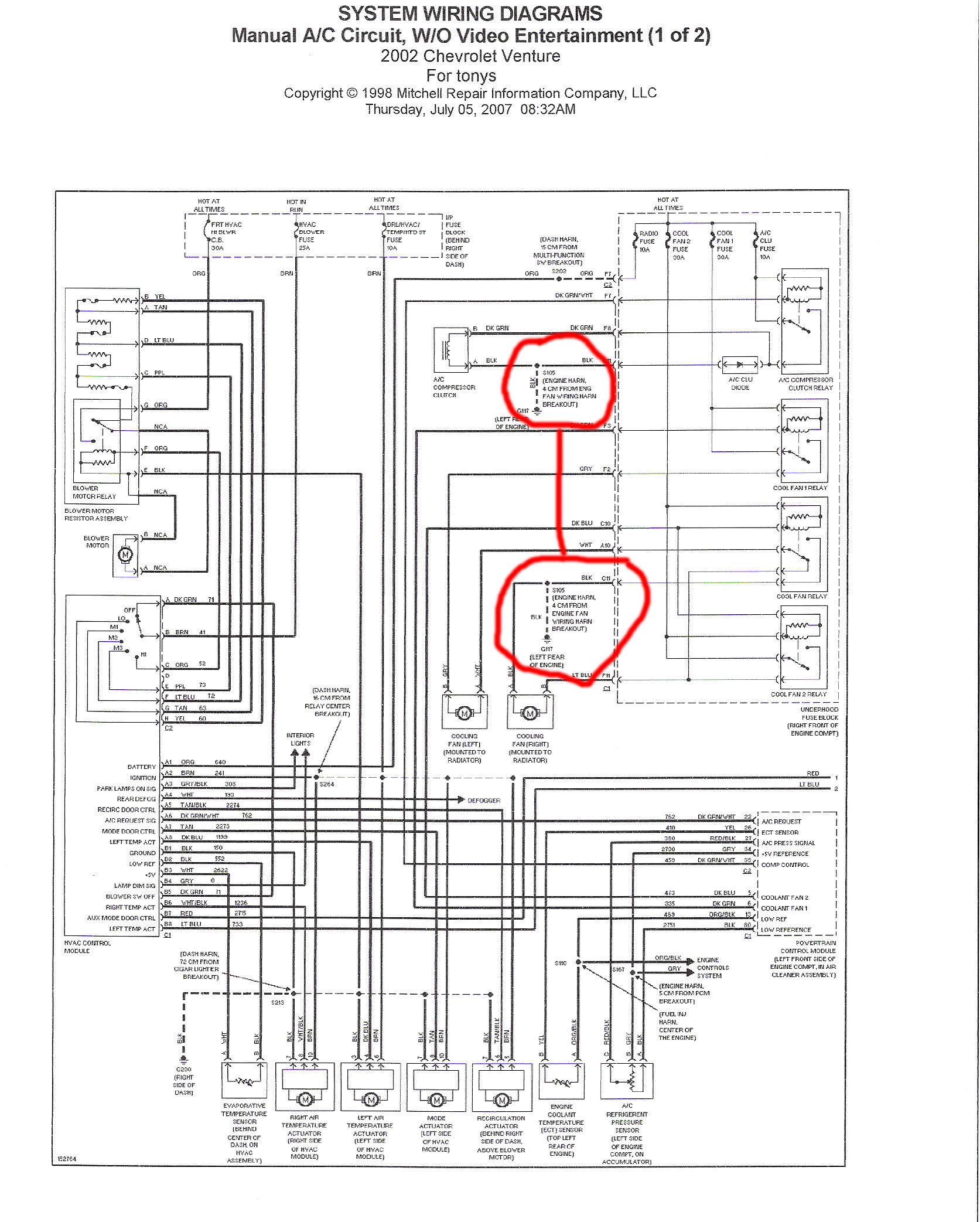
01 Chevy Venture Cooling Fans Ac Not Working Chevrolet Forum Chevy Enthusiasts Forums

50 Luxury Air Handler Fan Relay Wiring Diagram Ac Wiring Electrical Diagram Electrical Circuit Diagram
Need Help Reading This Wiring Diagram
Help My Ecobe3 Out Perform My 20 T Stat Diy Home Improvement Forum
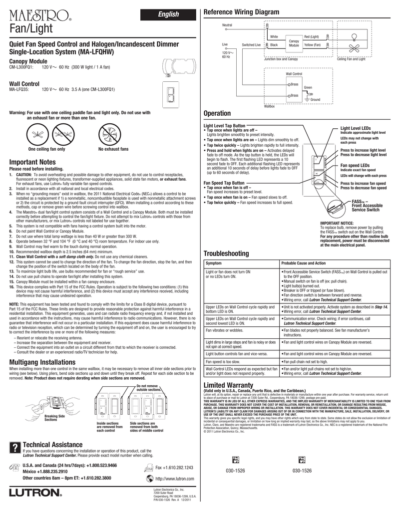
Maestro Quiet Fan Speed Control And Halogen Incandescent
1
2
Proper Fan Control Center Wiring Diy Home Improvement Forum

Is There A Wiring Diagram Available
0 Response to "45 fan center wiring diagram"
Post a Comment