40 paragon defrost timer wiring diagram
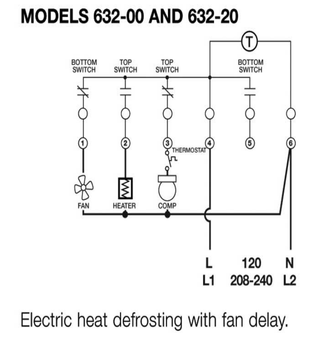
REFRIGERATION. D4. Product Drawings. 8047-00 and 8047-20. Electric Heat Defrosting. 8145-AV. H. (L/L1). N. (N/L2). F. HEATER.3 pages 2. Set Defrost Insert pin(s) to desired defrost time(s) on outer dial. 3. Set Defrost Duration Move copper pointer to desired duration of defrost time on inner dial. Install our Commercial Defrost Controls today to understand why Paragon® is Simply the Right Choice™ in Defrost Timers. An ISO 9001 - 2008 Certified Company 1 Year Limited ...
Then timer outputs can control 3-phase power using 3-phase contactors Contactor below is 3 phase with V coil http: Link below is for Paragon commercial box-type defrost timers http: I cant seem to find a wiring diagram on how to wire this correctly Link below has wiring diagrams and wiring manuals for V http: According to information from ...

Paragon defrost timer wiring diagram
DOWNLOAD. Wiring Diagram Pictures Detail: Name: paragon 8145 00 wiring diagram - paragon defrost timer wiring furthermore paragon defrost timer 8145 rh beinclover co. File Type: JPG. Source: 140.82.51.249. Size: 94.72 KB. 1 Operation and Functions The Paragon® Universal Defrost Timer series is ... press • Terminal G (defrost termination wiring connection) diagnostics Features ... Description: Paragon Defrost Timer Wiring Diagram Paragon Defrost Timer Wiring regarding 8145 20 Wiring Diagram, image size 577 X 600 px, and to view image details please click the image.. Here is a picture gallery about 8145 20 wiring diagram complete with the description of the image, please find the image you need. We hope this article can help in finding the information you need. 8145 20 ...
Paragon defrost timer wiring diagram. paragon 8141 00 wiring diagram - Building wiring layouts reveal the approximate places and interconnections of receptacles, illumination, as well as irreversible electric solutions in a building. Interconnecting cord paths may be shown approximately, where particular receptacles or fixtures must be on a common circuit. paragon 8045 00 wiring diagram another picture: rn 9068 paragon refrigeration programmable defrost timer rn 9068 paragon refrigeration programmable defrost timer pdf free download. paragon 8045 20 wiring diagram schematron org 12 11 2018 12 11 2018 4 comments on paragon 8045 20 wiring diagram wiring diagram shows both v and v l1 l2 is v l n is v i need wiring diagram for paragon the schematron ... Wiring for a single evap freezer system or reach in freezer. Any questions or comments Feel free to ask in the comment section . Thanks for watching 👍. ... Paragon 00 Wiring Diagram Defrost Timer Circuit Evaporator. The Paragon® Series Auto Voltage Defrost Timer is designed for commercial freezers Wiring Diagrams. AV. AV Heavy-duty steel case with electrical knockouts in the sides, Specifications. Operating Voltages: or / VAC, 60 Hz HEATER.
Find solutions to your paragon defrost timer 20 wiring diagram question. Get free help, tips & support from top experts on paragon defrost timer Adjustable Defrost Cycle Duration: 4 to minutes in S and Paragon Wiring Diagrams Electric Heat Defrosting S & S Series. how to test paragon 20 defrost timer rh waterheatertimer org Paragon 20 Wiring Schematic Paragon Time Clock tors, Paragon ... Collection of paragon defrost timer 8145 20 wiring diagram. A wiring diagram is a simplified traditional photographic depiction of an electrical circuit. It reveals the elements of the circuit as streamlined shapes, and also the power as well as signal links in between the tools. WALK IN FREEZER PARAGON DEFROST CONTROL. SUPCO Paragon Precision S814100 8141-00 6141-00 ... Normally closed thermostat used with defrost heater. Wiring using 120V or 240V single phase line compressor voltage common to timer. CYCLE LIMIT SWITCH HEATER COMP THERMOSTAT Wiring Diagrams Electric Heat Defrosting S8141 & S8145 Series Wiring Diagrams Electric Heat Defrosting S8041 & S8045 ...
Paragon 8045-20 defrost timer wiring diagram Tap image to zoom. Roll over image to zoom. Paragon 8040 series defrost timer Defrost frequency is one to six cycles per day Adjustable back up defrost termination from 4 - 110 minutes (2 minute increments) Time initiated/time terminated Choice of three contact arrangements for electric heat, The defrost timer is operated by a single-phase synchronous motor like those used to operate electric wall clocks, Figure 28-1. The contacts are operated by a cam that is gear driven by the clock motor. A schematic drawing of the timer is shown in Figure 28-2. Notice that terminal 1 is connected to the common of a single-pole double-throw ... The Paragon® Series Auto Voltage Defrost Timer is designed competitive voltage-specific mechanical defrost timers, eliminating Wiring Diagrams. Simple wiring. Resources: Paragon sell sheet shows model numbers and wirings diagrams, Replace with TT or CT series. The Latest Paragon® Defrost Timer • Universal Defrost Timers (UDT) Universal Defrost Timer - Wiring. Convert to Convert to Convert to N 1 4 32 X. Jun 20, · They are both commercial as well. I know when we draw up the schematic diagram the position of N and X are different.
Defrost Timer Wiring Diagram - WELOVEOTHERS
Paragon 8045 20 Wiring Diagram. Wiring diagram shows both V and V L1 L2 is V L N is V I need wiring diagram for Paragon The - schematron.org Website. The Paragon® defrost and the Tork® electric timers offer versatility and unbeatable quality Electric Heat,. If playback doesn't begin shortly, try restarting your device.
Paragon Timer Wiring Diagram
Dimension: 645 x 471. DOWNLOAD. Wiring Diagram Images Detail: Name: paragon 8141 00 wiring diagram - Paragon Timer Wiring Diagram Diagrams Schematics Throughout Defrost Time Clock 0. File Type: JPG. Source: natebird.me. Size: 193.58 KB. Dimension: 1659 x 891.
Appliance411 FAQ: How does a Frost Free Refrigerator's Defrost System Work?
Wiring Diagram. Models , and E -. the wiring diagram chosen. (Default setting B). 14 AWG OR LARGER WIRES RATED AT LEAST ⁰C. LISTED . and Electric Heat. •. •. •. Series Specifications. Uni-Line Applications and Wiring Diagrams. MECHANICAL.Paragon - V Defrost Timer - Designed for commercial freezers and refrigerators, Paragon commercial ...
Paragon Defrost Timer 8141-20 Wiring Diagram
The Latest Paragon® Defrost Timer • Universal Defrost Timers (UDT) • Works with multiple voltages • Removes built up of ice and frost • Easy to install • Simple to program • Part 9145-00 temp terminated • Part 9045-00 time terminated • Available as mechanism only without case - Add "M" to end of part number

Paragon 8145 00 Wiring Diagram Sample
Instruction Manuals. To find a publication quickly, you can use the " Filter " above the list to display by Category. You can also use the Search feature for a specific document title or category. You can sort the " Document Title " or the " Category " column using the button to the right of the column title.

Paragon Defrost Timer 8145 20 Wiring Diagram Gallery
The Paragon® 8000 Series Auto Voltage Defrost Timer is designed ... This all-in-one auto voltage defrost timer replaces over 40 ... Wiring Diagrams. 8145-AV.

River City II: Geometry Study (n.d.) // Bertrand Goldberg American, 1913-1997
Wiring Diagram For Defrost Timer Example Electrical Wiring Diagram • Paragon 8141 00 Wiring Diagram Free Download Wiring Diagram WIRE Architectural circuitry layouts show the approximate areas as well as interconnections of receptacles, lights, and also permanent electrical services in a building.

Paragon Defrost Timer 8145 20 Wiring Diagram Gallery
When trippers reach the trip switch, the timer relay turns on and defrost cycle starts. Defrost cycle starts. Refrigeration stops. Terminal 3 has power during ...1 page

selective focus photo of woman with sunglasses
Collection of paragon defrost timer 8145 20 wiring diagram. A wiring diagram is a streamlined traditional pictorial depiction of an electric circuit. It reveals the elements of the circuit as simplified forms, and also the power and also signal connections between the tools.
man wearing suit jacket and eyeglasses
Freezer Defrost Timer Live Operation on testing board.

Freezer Defrost Wiring Diagrams Hvac - Wiring Forums
Paragon Defrost Timer 8141-20 Wiring Diagram. Paragon - /V Defrost Timer - Designed for commercial freezers and refrigerators, Paragon commercial defrost controls provide. How to test Paragon defrost timer. Timer dial rotates continuously, and keeps good time. X Trippers are attached to edge of dial. When.

Mobile Delousing Unit, Truck Equipment, Plan of Operation and Erection Procedure, Presentation Drawing (1943) // Bertrand Goldberg American, 1913-1997
P PARAGON. 8000. Series. MECHANICAL. DEFROST. TIMER. Applications and Wiring Diagrams. WIRING DIAGRAMS FOR 8040 SERIES. ELECTRIC HEAT DEFROSTING.4 pages

men's white crew-neck T-shirt
I cant seem to find a wiring diagram on how to wire this correctly Link below has wiring diagrams and wiring manuals for V Paragon - /V Defrost Timer - Designed for commercial freezers and refrigerators, Paragon commercial defrost controls provide automatic defrost capability. Paragon 20 Wiring Diagram - Wiring Diagram Pdf Free Paragon 20 ...
Paragon Defrost Timer 8141 00 Wiring
Paragon 8141 20 Wiring Diagram. Paragon 8141 20 Wiring Diagram - wiring diagram is a simplified gratifying pictorial representation of an electrical circuit. It shows the components of the circuit as simplified shapes, and the faculty and signal links in the midst of the devices. A wiring diagram usually gives information nearly the relative ...
Untitled
Defrost Timers are the only multi-voltage defrost ... Applications and Wiring Diagrams. L, L1. N, L2. A. B. C. D. E. F. G. TIMER. COMPRESSOR.4 pages
8141-20 - Paragon 8141-20 - 208/240V Defrost Timer
DEFROST TIMERS An ISO 9001 - 2008 Certified Company Features and Benefits The Paragon® 9045-00 and 9145-00 Universal Defrost Timers are the only multi-voltage defrost timers engineered to refrigeration standards. At four defrosts per day, the Paragon Universal Defrost Timer switches last 16 years longer than competitive offerings. • Real ...

Typical wiring for defrost on a single evaporator freezer ...
Description: Paragon Defrost Timer Wiring Diagram Paragon Defrost Timer Wiring regarding 20 Wiring Diagram, image size X px, and to view image details please click the image. Here is a picture gallery about 20 wiring diagram complete with the description of the image, please find the image you need.

860-880 North Lake Shore Drive, Electrical Riser Diagram (11/28/1949) // Ludwig Mies van der Rohe (American, born Germany, 1886–1969) Associate Architect: Holsman, Holsman, Klekamp and Taylor (American, 20th century) Associate Architect: Pace Associates (American, 20th century) Structural Engineer: Frank J. Kornacker (American, active 1940s–1950s)
Paragon 8141-00 - 120V Defrost Timer - Designed for commercial freezers and refrigerators, Paragon commercial defrost controls provide automatic defrost ... Rating: 4.5 · 2 reviews · $102.67 · In stock
SOLVED: Paragon 8141-00 defrost timer wont turn. - Fixya
The Paragon® defrost and the Tork® electric timers offer versatility and unbeatable quality to control power and ... Temperature Terminated - Wiring Diagram.
Untitled
Description: Paragon Defrost Timer Wiring Diagram Paragon Defrost Timer Wiring regarding 8145 20 Wiring Diagram, image size 577 X 600 px, and to view image details please click the image.. Here is a picture gallery about 8145 20 wiring diagram complete with the description of the image, please find the image you need. We hope this article can help in finding the information you need. 8145 20 ...

Old Timers, Elko, Nevada (1974) // Jonas Dovydenas American, born Lithuania 1939
1 Operation and Functions The Paragon® Universal Defrost Timer series is ... press • Terminal G (defrost termination wiring connection) diagnostics Features ...

Barbed Wire and Fence Post (c. 1930, printed 1977) // Willard Van Dyke American, 1906–1986
DOWNLOAD. Wiring Diagram Pictures Detail: Name: paragon 8145 00 wiring diagram - paragon defrost timer wiring furthermore paragon defrost timer 8145 rh beinclover co. File Type: JPG. Source: 140.82.51.249. Size: 94.72 KB.

Paragon Defrost Timer 8141-20 Wiring Diagram

33 Paragon 8141 00 Wiring Diagram - Wiring Diagram Database

Defrost Timer Wiring Diagram - WELOVEOTHERS

Collection Of Paragon Defrost Timer 8145 20 Wiring Diagram ...
paragon timer wiring diagram - Wiring Diagram

Grasslin Defrost Timer Wiring Diagram - Wiring Diagram

8141-00 Defrost Timer Wiring Diagram

Paragon 8145-00 Defrost Timer not going into defrost cycle ...
Freezer Defrost Timer Live Operation - YouTube

River City, Aerial Perspective (1979) // Bertrand Goldberg American, 1913–1997

River City I: Phasing Plan (c. 1974) // Bertrand Goldberg American, 1913-1997

Dymaxion Car, Section (1933) // Richard Buckminster Fuller American, 1895-1983
Defrost Time Controls / HVAC/R Defrost Time Controls / HV AC/R

group of people wearing yellow and blue jersey shirts

Defrost Timer Wiring Diagram - WELOVEOTHERS
Paragon timers and manuals:
Paragon Defrost Timer Wiring Diagram - Wiring Diagram
Robertshaw 8000 Series Auto Voltage Defrost Timer manual | Manualzz
0 Response to "40 paragon defrost timer wiring diagram"
Post a Comment