42 electric motor brake wiring diagram
In this video, Jamie shows you how to read a wiring diagram and the basics of hooking up an electric air compressor motor. These tips can be used on most ele... A Repulsion Electric Motor is by definition a single phase motor which has a stator winding arranged for connection to the source of power and a rotor winding connected to a commutator. Brushes and commutators are short-circuited and are placed so that the magnetic axis of the rotor winding is inclined to the magnetic axis of the stator winding.
Xiaomi M Manual Online: Functional Schematic Diagram, Electric Scooter Body Assembly. Head Light Brake Handle Folding Mechanism In-wheel Motor. Post with 9 votes and views.

Electric motor brake wiring diagram
Generic Wiring Diagram READ THIS FIRST: Read and follow all instructions carefully before wiring brake control. Keep these instructions with the brake control for future reference. Important Facts to Remember 1. The brake control must be installed with a 12 volt negative ground system. Exico Electric Motors Limited 4 Stanton Road Finedon Road Industrial Estate Wellingborough NN8 4HN www.exico.co.uk Tel 01933 277930 Fax 01933 272184 Wiring Diagram - Single-phase motors 1EMPC - Permanent Capacitor Motors 1EMPCC - Capacitor Start Capacitor Run Motors ELECTRIC MOTORS LIMITED 7.0 Wiring Instructions Installation of the kits shall be performed to the proper wiring diagrams. In most cases, the diagram will be WD-0001 for the AC units and WD-0004 for the DC units. Route all wiring carefully so not to make contact with moving parts and secure with wire ties. Wiring and conduit connections must be made in accordance with ...
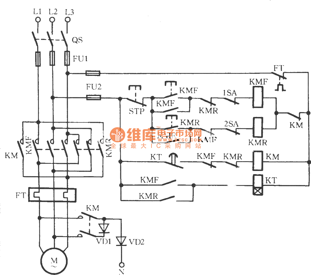
Electric motor brake wiring diagram. Mazda Protégé and Cars 1990-1998 and Ford Probe 1993-1997 Wiring Diagrams Repair Guide. Find out how to access AutoZone's Wiring Diagrams Repair Guide for Mazda 323, MX-3, 626, MX-6, Millenia, Protégé 1990-1998 and Ford Probe 1993-1997. Constructing a self-braking motor by building it onto the electric motor - a drive unit meeting ... volt while utilizing an appropriate rectifier. Basics 7 4.16 kV 3-Line Diagram : Basics 8 AOV Elementary & Block Diagram : Basics 9 4.16 kV Pump Schematic : Basics 10 480 V Pump Schematic : Basics 11 MOV Schematic (with Block included) Basics 12 12-/208 VAC Panel Diagram : Basics 13 Valve Limit Switch Legend : Basics 14 AOV Schematic (with Block included) Basics 15 Wiring (or Connection ... Connecting the motor directly to AC voltage will damage the motor and can cause fires and initiate an explosion. ... Wiring diagram motor with holding brake.
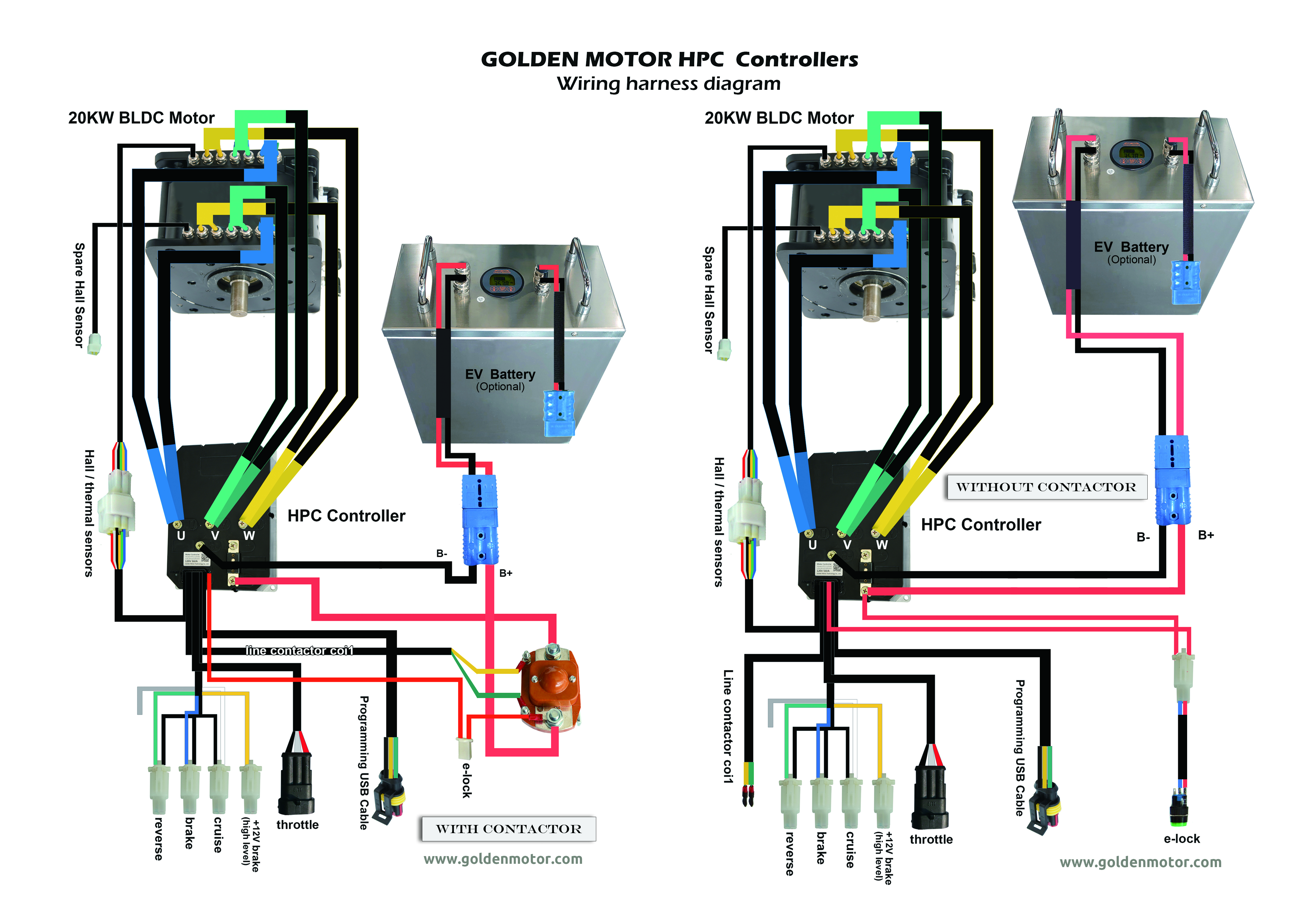
starter contactor with motor coasting with brake action disabled. Brake release function provides immediate means of opening the brake contactor. This feature adds operational flexibility and a safety factor as well. Figure 1-3 Functional Diagram - Master Mode Full Voltage Non-Reversing Controller Start/Stop/Jog Push Buttons Motor Brake Observe all local electrical and safety codes, as well as the National Electrical Code (NEC) and the. Occupational Safety and Health Act (OSHA). 3. Brake motors ... Baldor motor wiring diagram baldor 5hp motor wiring diagram baldor brake motor wiring diagram baldor dc motor wiring diagram every electrical structure is composed of various diverse parts. Yet with the help of this step by step guide this task will be become as easy as counting to five. To connect the brake switch to the controller's motor cut off wires and a brake light, a 48 Volt relay such as item # RLY-4860 will be needed. Here is the wiring diagram including the relay. Please let us know if you have any questions.
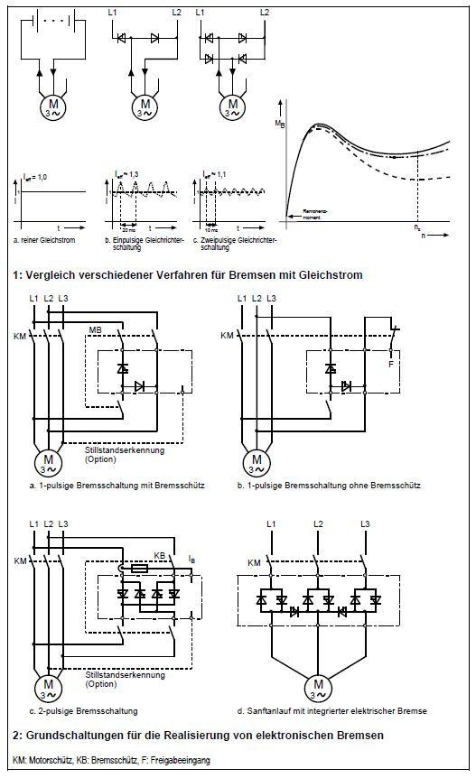
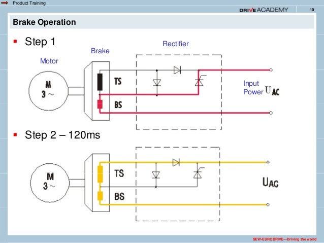
Rectifier for conversion of AC into DC current ... Motor. Brake. Rectifier. Input. Power. SEW-EURODRIVE—Driving the world ... Typical wiring diagram. UNDERSTANDING TOYOTA WIRING DIAGRAMS WORKSHEET #1 1. Describe the meaning of the "C13" in the diagram component Q. 2. Describe the meaning of the "G-W" in diagram component R. 3. Describe the meaning of the "2" in diagram component S. 4. Describe the meaning of the "S/D" in diagram component T. 5. Describe and identify the diagram component U. 6. I have a mobility scooter with an electromagnetic brake. The controller burned out and parts NLA. I purchased a SPD-24500A controller, a switch for reversing, a hall effect throttle and wired from scratch. The unit drives very well, but braking is a problem. I am at somewhat of a loss as how to wire the brake. I used an electronic relay that actuates at a range of 1.5vdc to 24vdc. always use wiring diagram supplied on motor nameplate. w2 cj2 ui vi wi w2 cj2 ui vi wi a cow voltage y high voltage z t4 til t12 10 til t4 t5 ali l2 t12 ti-blu t2-wht t3.org t4-yel t5-blk t6-gry t7-pnk t8-red t9-brk red tio-curry tii-grn t12-vlt z t4 til t12 tio til
NORD brake control rectifiers convert AC voltage to DC volt- ... NORD brake motors typically include the rectifier located in- side the terminal box.
Connection Diagram DT72 Example Motor Voltages: 230 /460 Volts - 60 Hz Brake Motor Connection ... For low ambient temperatures the BMH Brake Rectifier with a heating current is available for heating the brake while the motor is at rest. Electric heating is always ... of external wiring. The BMK Brake Control System - Optional for frame sizes 71 ...

The brake rectifier converts AC voltage into DC voltage. ... The operating instructions for the motor which is used (e.g. B1091 from the NORD.

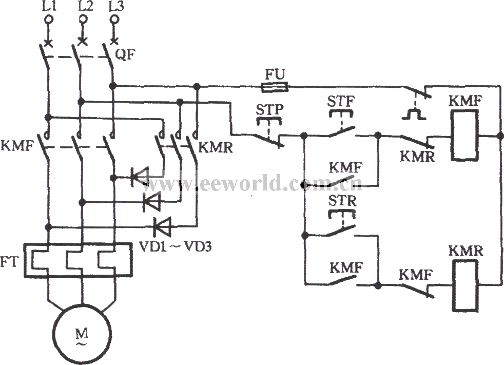
ON / OFF Three-Phase Motor Connection Power & Control Schematic and Wiring Diagrams. Three Phase Motor Connection Reverse and Forward - Power and Control wiring diagrams. Three Phase Slip Ring Rotor Starter - Control & Power Diagrams. Two Speeds One Direction Three Phase Motor Connection Power and Control Diagrams.

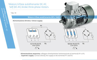
Brake type. Brake connection. Motor connection. Diagram. Motor rated voltage. Brake rated voltage. 1. AC - 3 phases (BA(X) only) Δ/Y(6w) Δ/Y (6w) Diagram. 265V/460V/60Hz, 330V/575V/60Hz, 220V/380V/60Hz,… 265V/460V/60Hz, 330V/575V/60Hz, 220V/380V/60Hz,… 2. YY/Y(9w) Diagram. 230V/460V/60Hz,… 230V/460V/60Hz,… 3. Single phase rectified ...
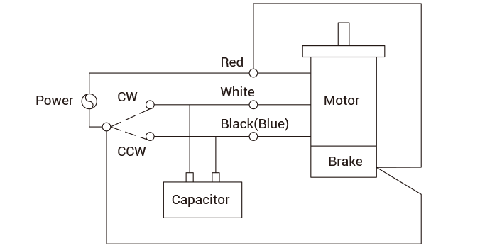
power is applied to the motor, the brake releases (requiring no additional brake supply wiring). The brake can be wired to the motor terminal block under the following conditions: a single speed motor, the motor is started and run across the line, and the brake voltage is equal to either the low or high motor voltage.
Gallery Of Ebike Wiring Diagram Download. Assortment of ebike wiring diagram. A wiring diagram is a simplified traditional pictorial representation of an electrical circuit. It shows the elements of the circuit as streamlined shapes, and the power as well as signal links in between the tools.

Baldor Motor Wiring Diagram - baldor 5hp motor wiring diagram, baldor brake motor wiring diagram, baldor dc motor wiring diagram, Every electrical structure is composed of various diverse parts. Each component should be set and connected with different parts in particular way. If not, the arrangement will not function as it should be.
Trailer Brake Wiring Diagram - The cost of a trailer mend by a professional can expense as many as $90 an hour or so. Just like just about anything, common servicing checks will help in averting some major troubles. Other cost-free preventative measures is usually used to reduce the chance of difficulties down the road, especially for probably the most adventurous of us who wish to prevent ...

Electric Brake Controller Wiring Diagram : Elecbrakes. Electric Brake Controller Wiring Diagram. Wiring Diagram. Auxiliary connection is optional, it may be connected to any 12v to 24v constant power source or left unconnected. Break away systems may be added to the service brake circuit. Elecbrakes is designed to operate 1 to 2 braked axles.
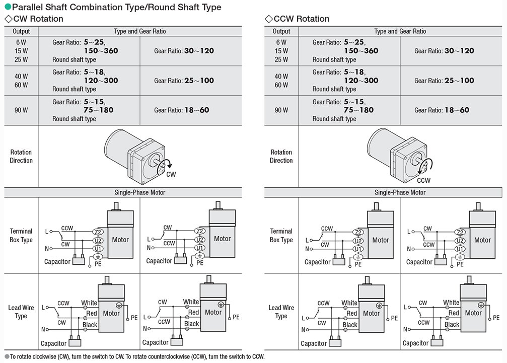
How to Wire a Three Phase Motor. A three-phase motor must be wired based on the diagram on the faceplate. The first step is to figure out the voltage of your phases. In the United States, for low voltage motors (below 600v), you can expect either 230v or 460v. That being said, there is a wide range of different motors and what you have on hand ...

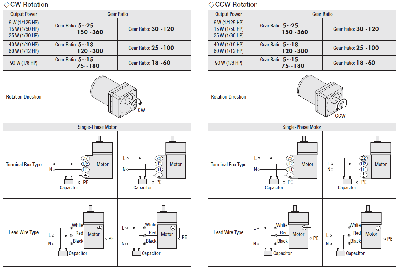
Electric Motor Wire Marking & Connections. For specific Leeson Motor Connections go to their website and input the Leeson catalog # in the "review" box, you will find connection data, dimensions, name plate data, etc. www.leeson.com Single Phase Connections: (Three Phase--see below) Single Voltage:
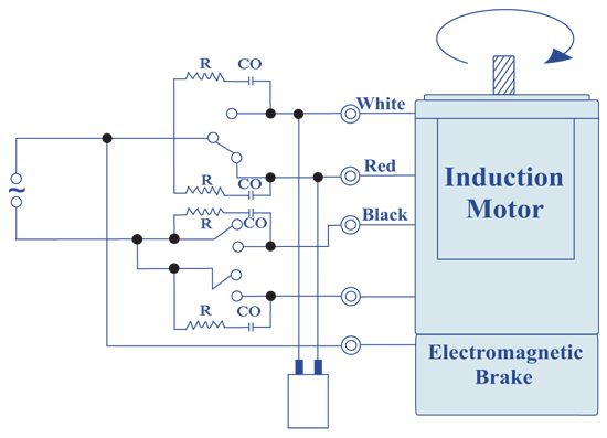
MrEngineers#mrengineers#induction motor brake wiring #solid State ... you will get much more video about electrical engineer field releted ...
Size: 752.70 KB. Dimension: 1920 x 1317. See also Solar Panel Wiring Diagram Schematic Download. DOWNLOAD. Wiring Diagram Pics Detail: Name: 2 axle trailer brake wiring diagram - Wiring Diagram For Tandem Axle Trailer Best Breakaway Kit Installation For Single And Dual Brake Axle Trailers.

TERMINAL MARKINGS AND INTERNAL WIRING DIAGRAMS SINGLE PHASE AND POLYPHASE MOTORS MEETING NEMA STANDARDS See Fig. 2-11 in which vector 1 is 120 degrees in advance of vector 2 and the phase sequence is 1, 2, 3. (See MG 1-2.21.)* MG 1-2.24 Direction Of Rotation
Dexter trailer brakes wiring diagram wiring diagram is a simplified good enough pictorial representation of an electrical circuit it shows the components of the circuit as simplified shapes and the capability and signal connections amongst the devices. Electric brake controllers provide power to the magnets to actuate the trailer brakes.

The brake is also 3 phase according to the tag. The tag on the brake says to see the tag on the motor for wiring information, but there is no such tag. The motor has wires labeled 1, 2, 3 and 3 more wires all labeled "B". So, I assume that 1, 2, and 3 are T1, T2, T3 for the motor. The "B" must be for the brake, but I'm not sure where to connect ...
Electric Motor Brake Wiring Diagram. Collection of electric motor brake wiring diagram. A wiring diagram is a streamlined standard photographic representation of an electric circuit. It shows the parts of the circuit as simplified forms, and the power and signal connections between the tools. A wiring diagram generally provides information regarding the family member setting…
Operating Instructions œ AC Motors DR / DV / DT / DTE / DVE / Asynchronous Servo Motors CT ... switching the motor and the brake. Using the wiring diagrams.

7.0 Wiring Instructions Installation of the kits shall be performed to the proper wiring diagrams. In most cases, the diagram will be WD-0001 for the AC units and WD-0004 for the DC units. Route all wiring carefully so not to make contact with moving parts and secure with wire ties. Wiring and conduit connections must be made in accordance with ...

Exico Electric Motors Limited 4 Stanton Road Finedon Road Industrial Estate Wellingborough NN8 4HN www.exico.co.uk Tel 01933 277930 Fax 01933 272184 Wiring Diagram - Single-phase motors 1EMPC - Permanent Capacitor Motors 1EMPCC - Capacitor Start Capacitor Run Motors ELECTRIC MOTORS LIMITED

Generic Wiring Diagram READ THIS FIRST: Read and follow all instructions carefully before wiring brake control. Keep these instructions with the brake control for future reference. Important Facts to Remember 1. The brake control must be installed with a 12 volt negative ground system.


0 Response to "42 electric motor brake wiring diagram"
Post a Comment