42 mac valve wiring diagram
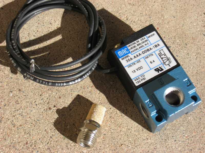
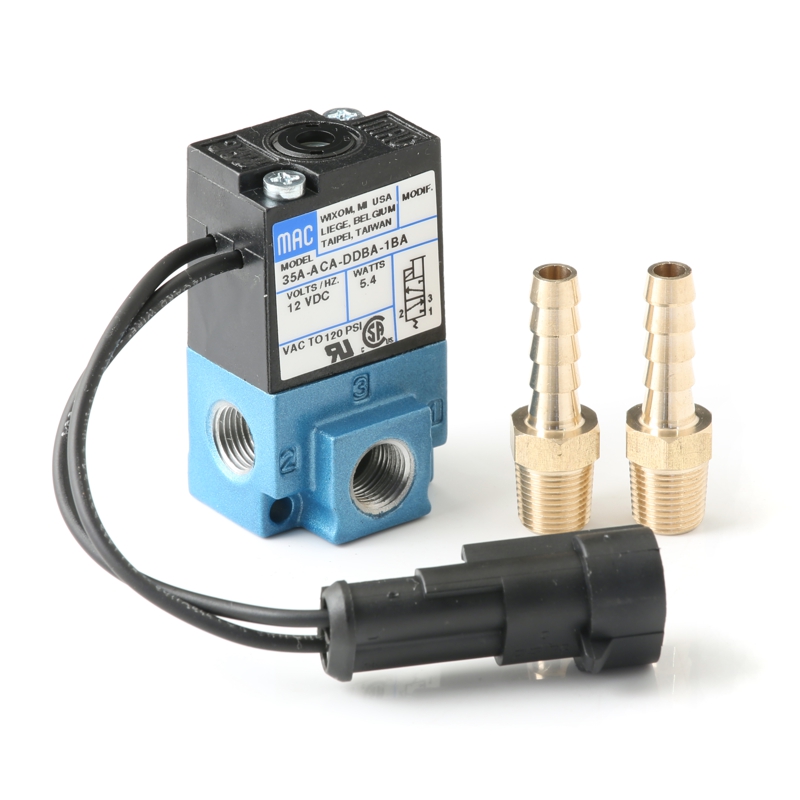
This kit includes 1/8″ barb fittings and mounting hardware. Maximum pressure is 125 psi, so this can be used even on wild high pressure compound turbo setups. Note: This valve is a perfect match for use with our MS3-Pro ECU as well as the MegaSquirtPNP and DIYPNP line of PNP EMS systems. Vacuum diagrams for current model boost control solenoid. MAC Advantage Brochure. 16 Pages. CIRCUIT BAR CATALOG. 288 Pages. Proportional pressure controller. 89 Pages. CURRENT TECHNOLOGY CATALOG. 359 Pages. NEW TECHNOLOGY CATALOG.
wiring diagram − type om w/obd 2013 eng product schematics 22437775 04 1 (2) 1 (52) wiring diagram index name description page ... valve 25a b frc1:f2 f29b2−0.8 cb52 spare/ brk. wear 15a b cb55 cir. heated mirrors 20a b f56 fuse telma 10a b cb57 hvac roof cond. fan 15a b spx2d frc1:f1 cb30 cir. brkr., muncie live pack 10a a b
Mac valve wiring diagram
The Mac Pilot Valve is connected to the Top of the Mac Valve (3100317). This valve is an electric over air solenoid valve used to dump. the air ride suspension. This Valve has been replaced by the Ride Air valve on 2007/2008 trailers. To see complete assembly refer to page 49. Part No: 3100106. Description: friendship (pick at most one) contact Someone you know how to get in touch with. Often symmetric. acquaintance Someone who you have exchanged greetings and not much (if any) more — maybe a short conversation or two. The fault code mid136 sid7 fmi 14.. modulation valve axle 1 left.. The truck is changing gears at 20rpm and above. Abs light on and it's sending a break failure signal.. We have changed the brake ecu and the modulation valve. We have tried and tried different ecu and modulation valve. Thanks for your advise #173. Peter (Thursday, 01 October ...
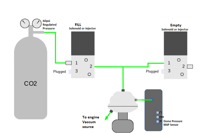
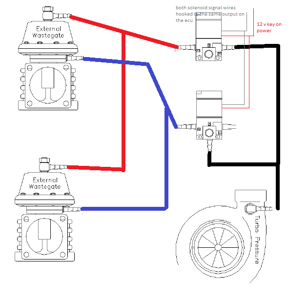
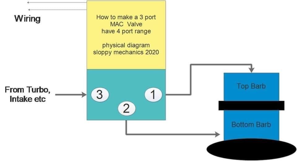
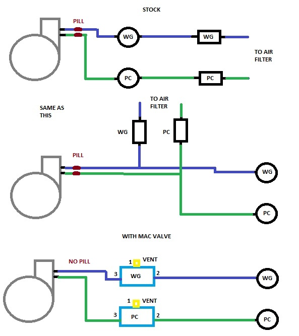
Mac valve wiring diagram. "Remember me" stores your User ID on this computer. You should not use this feature on public computers. Mac Valves. For over 70 years MAC Valves, Inc. has been a global manufacturing leader of pneumatic and more recently fluid valves for industry. MAC's innovative technology featuring our patented poppet, spool and recently developed Bullet Valve®️ raised the performance bar in valve technology. We design and manufacture valve solutions ... MAC VALVES INC. has earned a reputation as an innovator in solenoid air valve technology as is ... shifting force through more core iron and magnet wire. I've been having issues with the low dollar 4 bar MAP sensor not scaling correctly, so Ive given up and went to boost control. I'm currently setting up dome and dual MAC valves on my setup with CO2. How are you guys wiring up these? I've sat there forever wondering. I know two go to 12V keyed, one + & one - etc., but the output list I got with the Terminator kit are all positive and no idea on ...
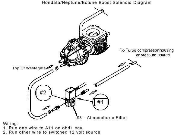
This manual contains information and diagrams related to wiring most Holley EFI products including ECU's, ignition systems, nitrous systems, water/methanol injection systems, sensors, and more. 3 1.1 Important Wiring "Do's and Don'ts ... 24712201 Electric / Air Control Valve 1945 Normally Closed 24712202 Electric / Air Control Valve 2345 Normally Open 24712212 12V Parker Inline Pilot Valve 24000604 Breather www.mactrailer.com MAC Trailer Mfg. 1-800-795-8454 parts@mactrailer.com Part Sales 1-800-647-9424 TS MATIC 3 Mac Valve Wiring Diagram - One of the most difficult automotive repair tasks that a mechanic or repair shop can say yes is the wiring, or rewiring of a car's electrical system.The misfortune in reality is that every car is different. considering bothersome to remove, replace or repair the wiring in an automobile, having an accurate and detailed mac valve wiring diagram is critical to the ... wiring diagram index, 12v NAME DESCRIPTION Page NAME DESCRIPTION Page AA-O POWER DISTRIBUTION 1/2 2 GD LIGHTING-FORWARD/SIGNAL (CXU,GU7,GU8) 30
Manufacturer of industrial grade heat press machines for t shirts, mugs, caps, tiles, plates, and more. The best heat presses, including manual heat presses, automatic heat presses, large format and custom heat transfer press equipment, are all made in the USA by Geo Knight & Co Inc. MAC Valves, INC. 30569 Beck Rd; Wixom, MI 48393; 248 624 7700; 1 800 MAC VLVS; mac@macvalves.com "Valves That Don't Stick" ©2021 macvalves inc. ... Mac Valve Wiring Diagram Collection. December 20, 2020 by Jonathan Guttberg. Mac Valve Wiring Diagram Collection. Avoid shortages and malfunctions when electrical wiring your car's consumer electronics. Before you start any DIY electrical wiring project, it's important that you have the right ingenuity, as well as the right tools and ... WIRING DIAGRAM The SV71 and SV73 solenoid valves are a compact, light-weight solenoid that can be used in intrinsically safe applications. It is important to note that a proper safety barrier needs to be used in conjunction with the solenoid valve. Solenoids come standard with both 3-Way and 4-Way field conversion kits.
Please SHARE THE VIDEO!Click here if you're interested in subscribing: http://bit.ly/Sub2BEAVISBEAVIS Motorsport on Patreon http://www.patreon.com/BEAVISmot...
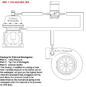
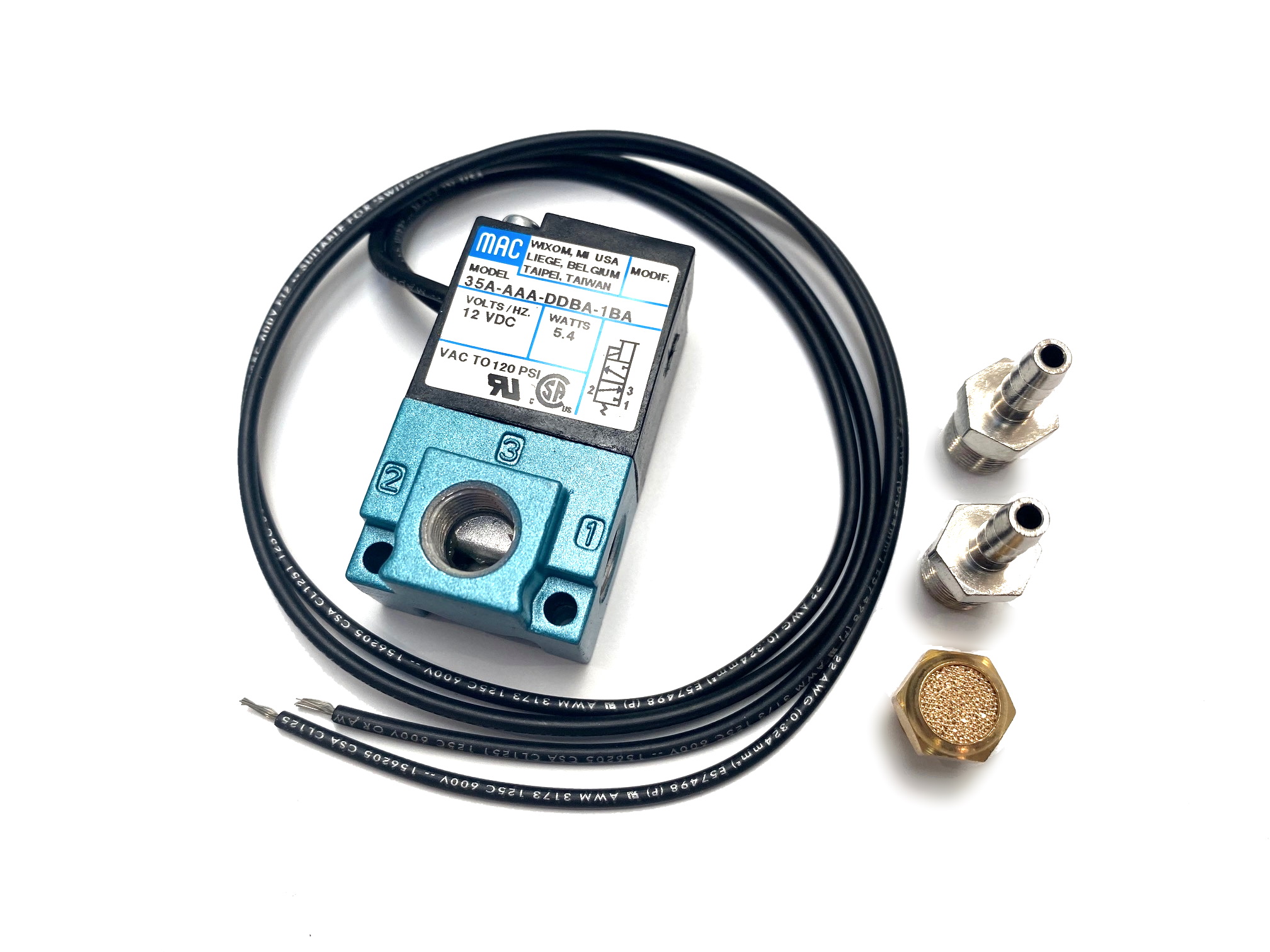
MAC Boost control solenoid piping and wiring - Microsquirt by sweet_baby_james » Wed Aug 05, 2015 2:04 am I have a MAC 35A-AAA-DDBA-1BA solenoid valve that I want to use for boost control using my Microsquirt running 3.3.2.

HEATING ONLY - WIRING DIAGRAMS instructions and wiring diagrams. See Figures 4,5,6,7 and 16 C. Use of Indirect Storage Tank (DHW): • Indirect storage tank, use only tank sensor to interface with boiler. Wire sensor to M2 terminals #9 and #10. • Use of booster pump to increase flow rate to indirect tank is not recommended by manufacturer.

• Pilot valve : PME-XXyZZ, including seal 16337. • Pressure seal between valve and base : 16246. • Mounting screw valve to base (x4) : 32201. • BSPP threads. Spare parts : Options : dimensions technical data Dimensions shown are metric (mm) Consult "Precautions" page 364 before use, installation or service of MAC Valves 100% 18 100% ...
Apr 05, 2000 · The alternator is connected to the engine by a belt and generates electricity to recharge the battery. The battery makes 12-volt power available to everything in the car needing electricity (the ignition system, radio, headlights, windshield wipers, power windows and seats, computers, etc.) through the vehicle's wiring.

Mac Trailer Wiring Diagram - People today understand that trailer is a vehicle comprised of quite complicated mechanics. This automobile is designed not just to travel 1 location to another but also to take heavy loads. This article will be discussing mac trailer wiring diagram.What are the advantages of understanding such understanding?
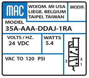
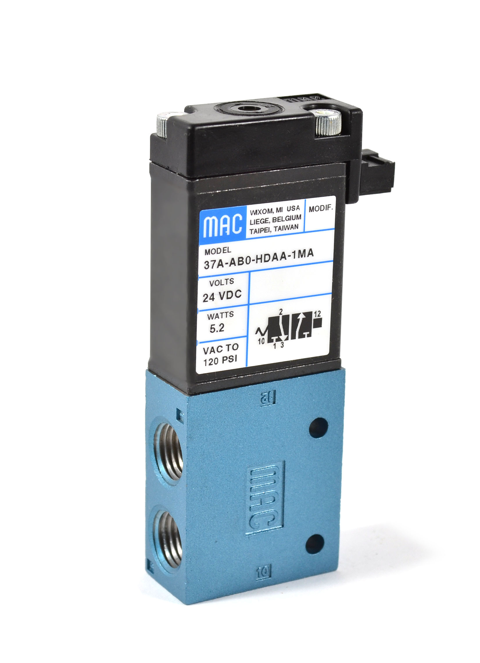
Directional air control valves are the building blocks of pneumatic control. Pneumatic circuit symbols representing these valves provide detailed information about the valve they represent. Symbols show the methods of actuation, the number of positions, the flow paths and the number of ports. Here is a brief breakdown of how to read a symbol.

Nov 19, 2021 · Hino jo8c injector pump timing. Product Type: Engines. timing mark for commonrail pump no4c hino engine. Fire Pump Drives. If the timing pin or bolt can not be installed, the fuel injection pump camshaft must be put into time again before Step 4 is done. lb) Specifications 4j hino motors, ltd j05c -tb/td 5.
8f614 Mac Solenoid Valve Wiring Diagram Digital Resources Solenoid Valves Interfaces Between The Electric Control Level And Exd 5 2 Namur Solenoid Valve Mono Stable Hydraulic Multiplier Selector Diverter Solenoid Valve W Switch Solenoid Valve Remote Control Everything ...

Nov 17, 2021 · Mack mp8 coolant filter shut off valve

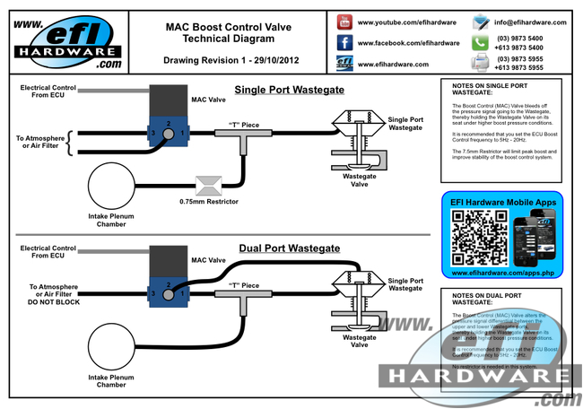
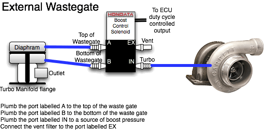
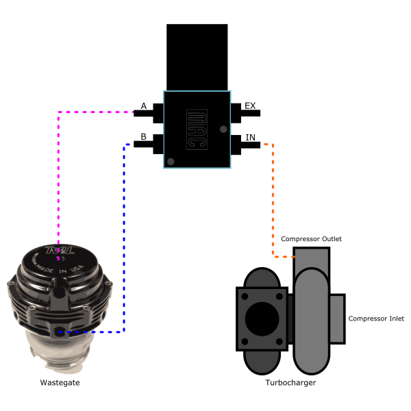
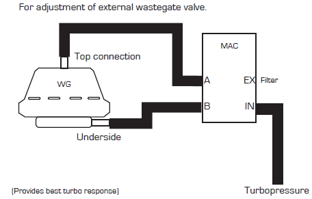
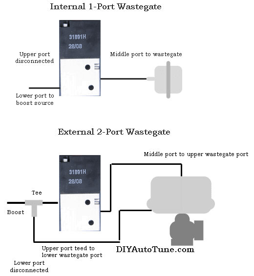
This covers the selection, connection and wiring of the boost control ... the boost control solenoid operates as a bleed valve, venting pressurized air from ...
MAC Trailer Aftermarket Parts Inc., maintains an extensive inventory in our 30,000 sq ft warehouse. Inventory including the entire line of MAC captive trailer items and extrusions to hoists, suspensions, lights, wet kits, MAC cleaners, 5th wheel plates for trucks and trailers, air-operated lids for tanks, check valves, bottom tees, moving floor ...
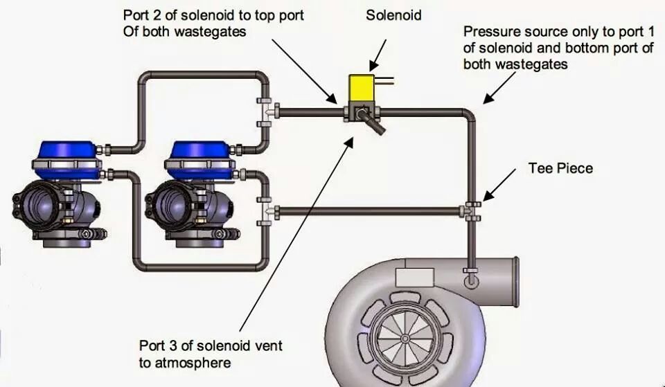
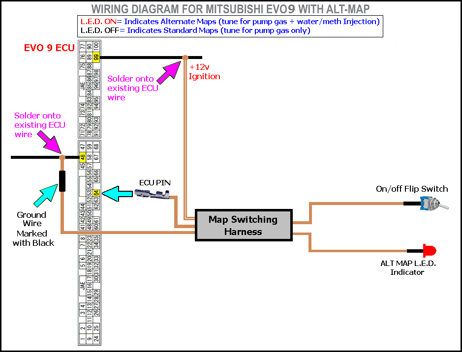
27 Jan 2008 — Forced Induction - Mac solenoid wiring - My tuner and i are wiring up a Mac boost solenoid. We soldered everything in the ECU.How do i plumb and wire in dual MAC valves for boost control?12 Jun 2013setting up PWM - Honda-Tech - Honda Forum Discussion19 Apr 2017More results from honda-tech.com
power distribution frc 1/2 wiring diagram: aa spf44a spx03ea3 fb2a1-0.8 ag:0 b a17.b:2 ai:4 c frc_j3:c5 aq:1 b mcsc:a9 f61a1-0.8 hb:2 d a131b.a:4 f15a1-5.0 bi:3 c x210a.a:d f87 15a cust. a b f71 15a center pin hot a b f60 30a hvac fan a b f61 5a lvd sens/ vendor ttu a b f76 30a 3968162 a f05 30a lecm4 b f06 20a rh sleeper pwr ports/ console b ...
3. Wire the fill (+) solenoid to the to the ECU's output pin that you chose. In this example it was J1B10 (or pin G on the IO connector). 4. Connect the other side of the solenoid to a switched 12V power source. 5. Wire the vent (-) solenoid to the to the ECU's output pin that you chose. In this example it was J1B3 (or pin H on the IO ...
Boost solenoid (s) are not polarity sensitive. Wire 1: +12V Wire 2: GPO (GND) Single solenoid valve Solenoid for boost control (MAC 35A-AAA-DDBA-1BA), +12v, ...
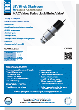
Committed to the design and manufacture of high-tech valve solutions for our customers around the globe. Since 1948, MAC Valves, Inc. has worked to establish and maintain global technological leadership in the design and manufacture of pneumatic and fluid valves, proportional valves, flow control, and regular technology.
Mac Solenoid Valve Wiring Diagram. 2-way and 3-way configurations of the BV10 cartridge are available. Wiring Diagram for Honeywell 3 Port Valve Wiring Diagram image size 730 X 595 px. Y plan central heating system wiring diagram plumbersforums net honeywell 3 port mid position valve v4073a 1039 diynot forums s cannot have ch on by itself w how ...

MAC 1175 Summer Air Circulator Receptacle Unit Switch-+ 7. Run the wires attached to the timer through the bushing at the bottom of the control box and install the bushing. 8. Connect the wires per the wiring diagram. (See Figure 1) 9. Attach the control box cover. 10. DELAY ON MAKE dial should be set for 60 seconds. 11. DELAY ON BREAK dial ...
12 Apr 2016 — I have a K20z3 engine Gen 8 Have 2 wires in the Mac valve solenoid boost controller. Can someone tell me where to connect the wires to the ...
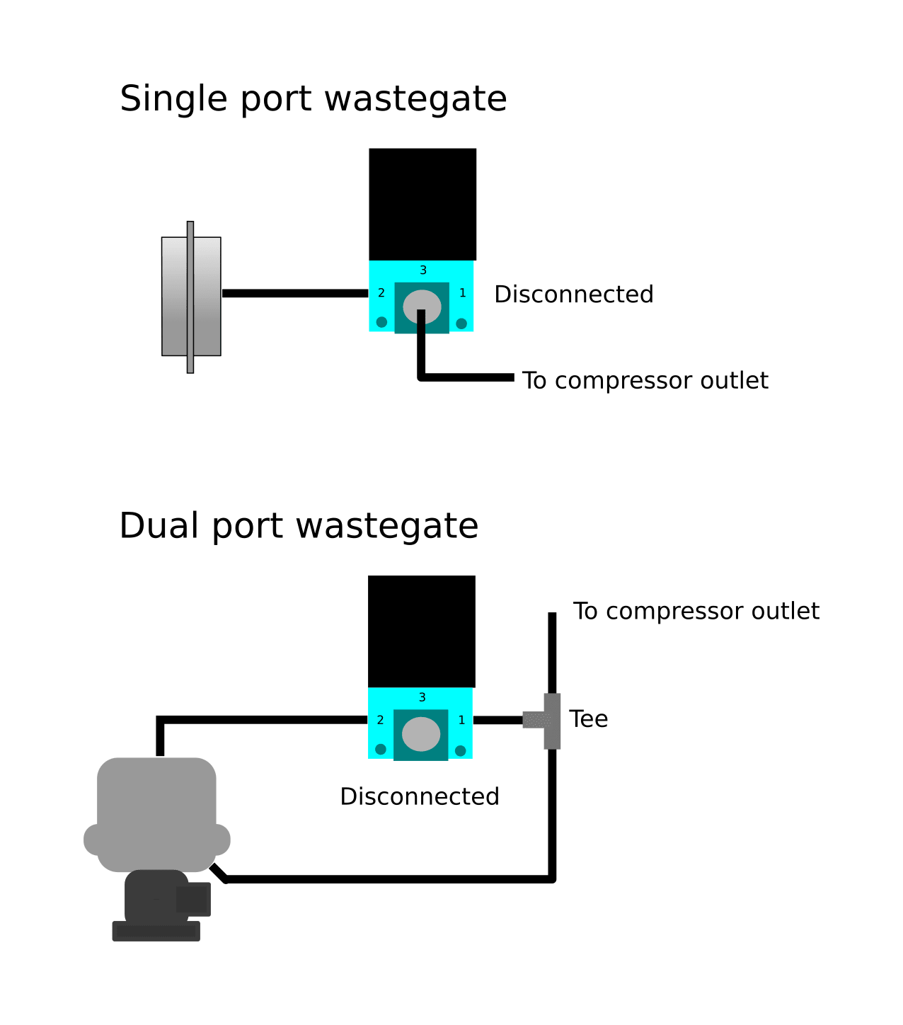
Wiring Information MAConnect Information™ Precautions Page 31 32 34 MAC Valves Commonly Ordered Products Catalog Table of Contents. Valve Function 2-Way Valve Function Normally Closed (N/C)=Non-Passing. Normally Open (N/O)=Passing. Plug a port on a 3-way to make it function like a 2-Way. Typical Application: an Airjet Blow Off application.
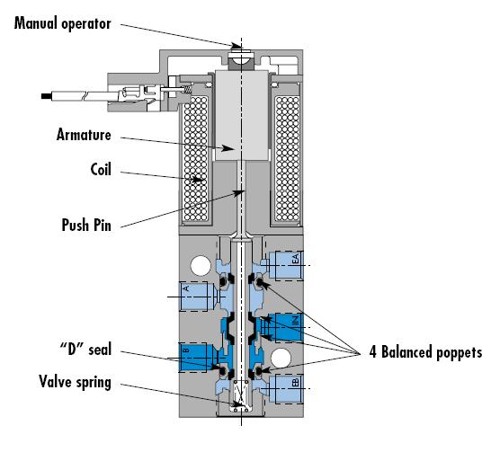
The MAC 82 Series is a versatile 4-way solenoid piloted spool valve. This series features our balanced poppet in the pilot and an air/spring return for consistent shifting regardless of inlet pressure fluctuations.. Our balanced spool means the valve can be piped as a 4-way, 3-way, 2-way, normally closed or normally open or can be used for vacuum, diverter or selector applications.

Always check the latest information at the "Wiring Diagrams" location. Utilization of Body Builder connectors ordered and provided by Mack is strongly recommended as your power, lighting, and ground source for body installation, PTO installation, and operation. Cutting into wiring harnesses is not recommended as it may affect CAN Bus messaging.

The fault code mid136 sid7 fmi 14.. modulation valve axle 1 left.. The truck is changing gears at 20rpm and above. Abs light on and it's sending a break failure signal.. We have changed the brake ecu and the modulation valve. We have tried and tried different ecu and modulation valve. Thanks for your advise #173. Peter (Thursday, 01 October ...
friendship (pick at most one) contact Someone you know how to get in touch with. Often symmetric. acquaintance Someone who you have exchanged greetings and not much (if any) more — maybe a short conversation or two.

The Mac Pilot Valve is connected to the Top of the Mac Valve (3100317). This valve is an electric over air solenoid valve used to dump. the air ride suspension. This Valve has been replaced by the Ride Air valve on 2007/2008 trailers. To see complete assembly refer to page 49. Part No: 3100106. Description:


0 Response to "42 mac valve wiring diagram"
Post a Comment