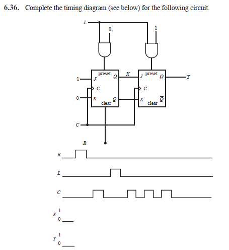
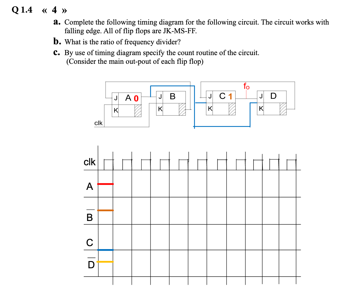
43 complete the timing diagram for the following circuit
Advanced Member level 2. Hi All. I have built a timer circuit using Transistor. (Circuit Diagram Attached) The power source is 24V 3 Amps Transformer. and i am operating a 24V 10 RPM AC Motor for one of my application. On Power ON, The motor will be ON for a specific period of time and the time is decided by C1 Capacitor and R2 and RV1 Resistor ... The following diagram provides a conceptual overview of how this works: The diagram can be roughly divided into three areas: The Device Management service syncs update information (title, description, applicability) from Microsoft Update using the Server-Server sync protocol (top of the diagram).
• As part of the development team, perform one or more of the following development activities; develop or review circuit diagrams, define harnesses, specify and support tests in production. • Support product lead with bid support, analysing requirements from customers or system architects and translate them into requirements valid for the ...
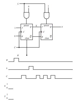
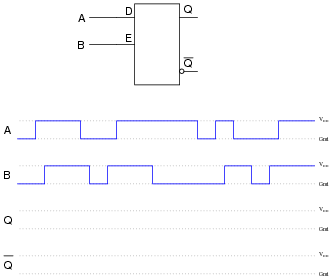
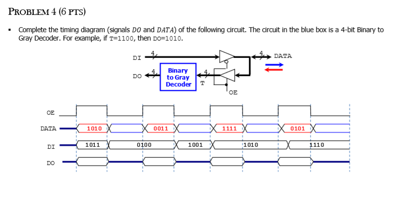
Complete the timing diagram for the following circuit
If you want to learn more about the 555 timer, the book Timer, Op Amp, and Optoelectronic Circuits and Projects Book Vol. 1 By Forrest Mims is a great resource to have on your bench. The book has lots of information about the 555 timer, OpAmps, and other IC's too. You can watch how each of the circuits in this tutorial work in this video: When I used TUS6111ARSVR chip to complete the usB-to-UART function design of my hardware control board, I found that when I inserted the USB cable into my computer, the computer could not connect with the control board.TSU6111ARSVR chip does not realize automatic detection (This document mentions ... Circuit diagrams are graphical representations of circuits or electrical devices. Each component of a circuit has a corresponding standard symbol (see Figure 2). When drawn, these symbols are linked together to show the construction of a circuit; the resulting diagram is a map that anyone can read to see how to build the circuit.
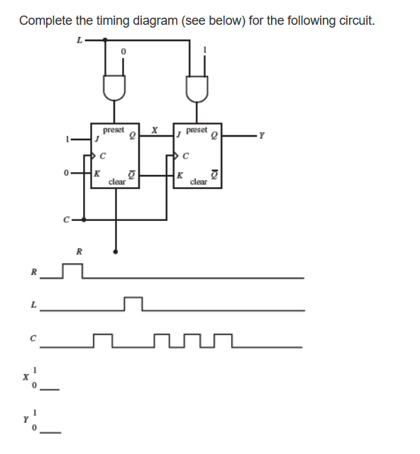
Complete the timing diagram for the following circuit. WASHINGTON -- The United States and South Korea fully agree on the need to denuclearize the Korean Peninsula through diplomacy, a state department spokesperson said Monday, reaffirming US ... Using Machine Learning to Optimize FPGA Layout and Timing. by Max Maxfield. As usual, I'm amazed by how fast and how far things have changed in my own lifetime. When I started my career in electronics and computers in 1980, we thought simple programmable logic devices (PLDs) were pretty darned cool, not least that their creators managed to ... FY2021 Orovalle Highlights: 63 K Au Oz Eq produced (47.4 K Au Oz, 6.3 M Cu lb and 166 K Ag oz). COC at $1,043 and AISC at $1,376. FY2022 Orovalle Guidance: Gold: 48K - 53 K Au Oz Copper: 5.8 M ... A complete circuit is a complete loop with electricity flowing the way it's supposed to flow: from the battery, to the component, and back to the battery again. An open circuit is an incomplete ...
WASHINGTON -- South Korea's vice foreign minister held talks with his US counterpart and discussed ways to bring North Korea back to dialogue, including the possible declaration of a formal end to ... Sequence Diagram Tutorial: Complete Guide with Examples; Business Process Modeling Tutorial (BPM Guide Explaining Features) Use Case Diagram Tutorial ( Guide with Examples ) Join over thousands of organizations that use Creately to brainstorm, plan, analyze, and execute their projects successfully. By AFP. December 01, 2021. JEDDAH: Saudi Arabia's debut Formula One race will showcase the country to the world, its motorsports chief told AFP, hitting back at criticism over human rights. The ... Constructing Cell Diagrams (Cell Notation) Because it is somewhat cumbersome to describe any given galvanic cell in words, a more convenient notation has been developed. In this line notation, called a cell diagram, the identity of the electrodes and the chemical contents of the compartments are indicated by their chemical formulas, with the ...
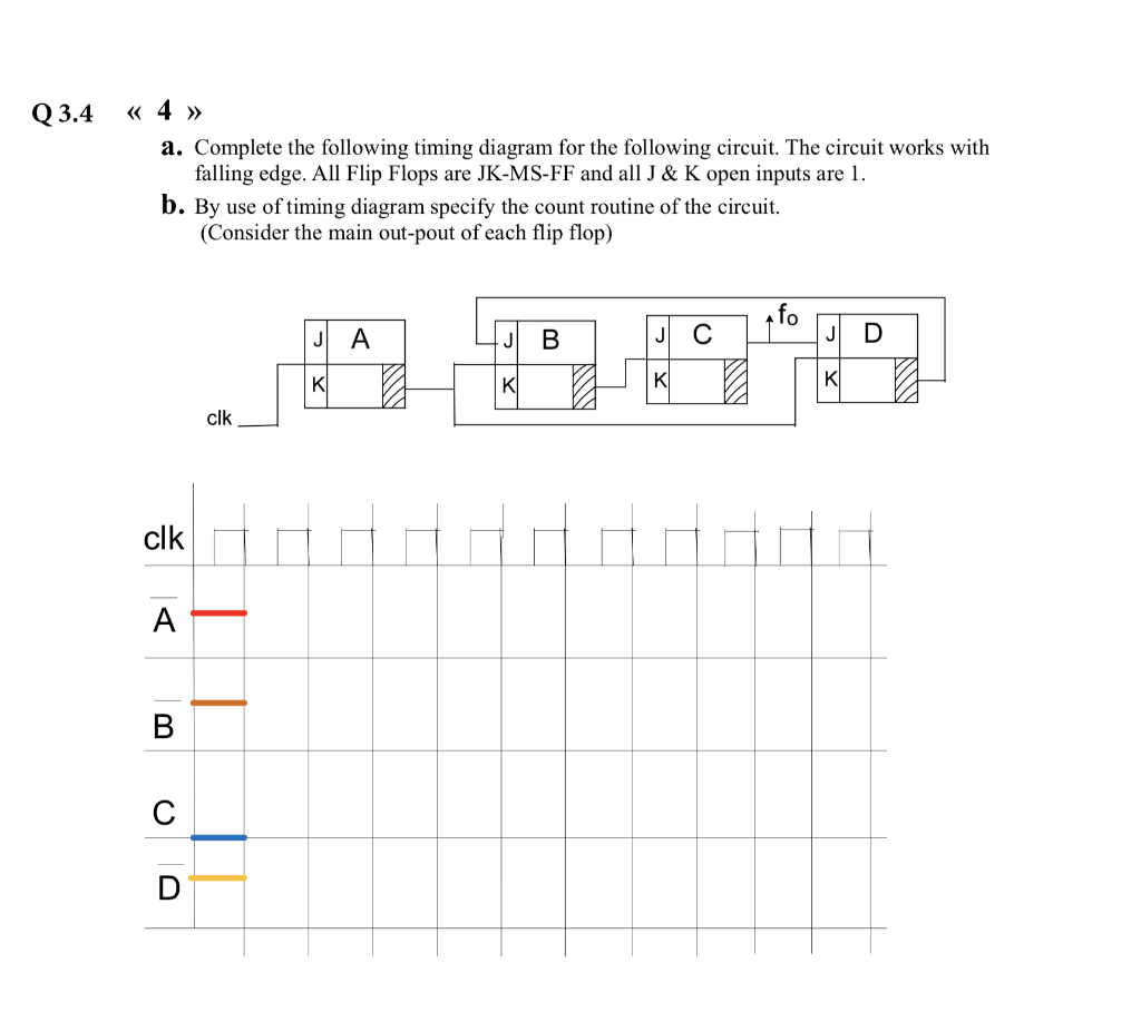
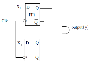
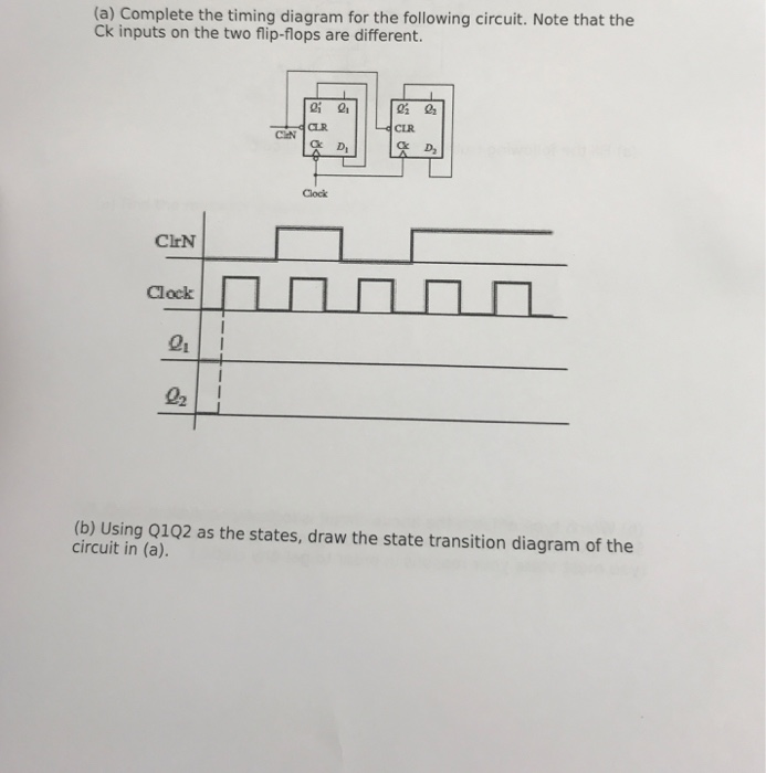
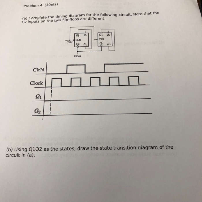
Truth table and circuit produced from the timing diagram in Fig. ... Draw a timing diagram with the following signals (where [t1,t2] is the time interval ... Effect diagram after assembling . 11. Then fix A06 to A04. Effect diagram after assembling . 12. Connect A05 with A08 and A11. Assemble the following components . Effect diagram after assembling . 13. Fix A05 to A04. Assemble the following components . Effect diagram after assembling . 14. Fix the rocker arm under A04 with the servo on A02. (b) Complete the timing diagram for the following circuit. Note that the Ck inputs on the two flip-flops are different. ClrN Q. Clock 9í CIEN CLR Ck Q||||Q5 ...1 answer · 0 votes: → Flip flops are D-flip flops. for B-flap Hops Qn+1 = D. - from the input is given taken circuit, we can see from Q' [ 0 = Qi] [Da= 0; / Truth table ... Question: 6.35. Complete the timing diagram for the following circuit. 0 D 0 CK 0 aCK 0. This problem has been solved!
Sanmina (NASDAQ:SANM) updated its first quarter 2022 earnings guidance. The company provided EPS guidance of $0.900-$1.000 for the period, compared to the consensus estimate of $1.010. The company also issued revenue guidance of $1.60 billionillion-$1.70 billionillion, compared to the consensus estimate of $1.76 billionillion.
SR Flip flop - Circuit, truth table and operation. SR flip flop, also known as SR latch is the basic and simplest type of flip flop. It is a single bit storage element. It has only two logic gates. The output of each gate is connected to the input of another gate. The state of the SR flip flop is determined by the condition of the output Q.

Nanoleaf is a brand of smart lighting in the form of color-changing triangular or hexagonal panels. With an Arduino, 3D printed enclosure, and LED strips, you could make your own similar geometric-style lighting fixtures.. While the maker has used an ESP8266 based WeMos D1 Mini Pro, it's noted that it could be swapped out with an Arduino Mega.

Students investigate circuits and their components by building a basic thermostat. They learn why key parts are necessary for the circuit to function, and alter the circuit to optimize the thermostat temperature range. They also gain an awareness of how electrical engineers design circuits for the countless electronic products in our world.
According to the Pourbaix diagram of Cu (Supplementary Fig. 3a), the open circuit potential (OCP) of Cu 2 O in 0.1 M KHCO 3 solution (pH 6.8) in darkness (~0.65 V versus reversible hydrogen ...
A circuit is the path that an electric current travels on, and a simple circuit contains three components necessary to have a functioning electric circuit, namely, a source of voltage, a conductive path, and a resistor. Circuits are driven by flows. Flows are ubiquitous in nature and are often the result of spatial differences in potential energy. Water flows downriver due to changes in height ...
Harvard University has added caste as a protected category for all graduate and undergraduate student workers. The historic addition marks Harvard as the first Ivy League school to have caste ...
Referring to a previous question which I solved, it was related to a inverting boost configuration of the MC34063 with the following arrangement:. I realized my circuit and calculations were right, and the question was solved. What remained open, though, was another issue: why from the measurements the Vsat of the internal switch was 1.6V or so, while by following the components selection, it ...

Circuit of D flip-flop. D Flip Flop is the most important of all the clocked flip-flops as it ensures that both the inputs S and R are never the same at the same time.It is constructed by joining the S and R inputs with an inverter in between them, as shown below. Thus the D flip flop has single input(D).
It will be a seasonable and sunny weekend across the Tennessee Valley! This is all thanks to an area of high pressure that is in control of the region keeping dry air in place. After a bitterly ...

Here 'I' is the instruction length. The notations (t1, t2, t3) represents successive time units. We assume that a clock is available for timing purposes and it emits regularly spaced clock pulses. Each clock pulse defines a time unit. Thus, all time units are of equal duration.
This is the complete circuit diagram for this home automation project. I have explained the circuit in the tutorial video. The circuit is very simple, I have used the GPIO pins D23, D22, D21, D19, D18, D5, D25 & D26 to control the 8 relays.. And the GPIO pins D13, D12, D14, D27, D33, D32, D15 & D4 are connected with Switches to control the 8 relays manually.
Complete the timing diagram of the following circuit. G = G-G2G,Go-1011, Q Q3QaQ1Qo resetn clk clk... Question ...

Mar 28, 2021 — PROBLEM 1 (13 PTS) Complete the timing diagram of the following circuit. G =GzG2G, Go = 1101, Q = Q3Q20.lo. Q3 Q. 1011 resetn o x. Po D, 0. B o1 answer · 0 votes: Answer:what is that?Explanation:
Tyre choices for the 2021 Saudi Arabian Grand Prix. This brand-new circuit will see Pirelli bring its C2, C3 and C4 compounds to Saudi Arabia to run as the hard, medium and soft respectively ...
Introduction of K-Map (Karnaugh Map) In many digital circuits and practical problems we need to find expression with minimum variables. We can minimize Boolean expressions of 3, 4 variables very easily using K-map without using any Boolean algebra theorems. K-map can take two forms Sum of Product (SOP) and Product of Sum (POS) according to the ...

Nov 12, 2021 — 1 Answer to (10%) Complete the timing diagram for the following circuit (Q starts with "0"): Clock CE Clock Clock.1 answer · Top answer: Answer: Summary- The circuit is analyzed and the output timing diagram is also drawn. Solution is attached below.
Circuit diagrams are graphical representations of circuits or electrical devices. Each component of a circuit has a corresponding standard symbol (see Figure 2). When drawn, these symbols are linked together to show the construction of a circuit; the resulting diagram is a map that anyone can read to see how to build the circuit.
When I used TUS6111ARSVR chip to complete the usB-to-UART function design of my hardware control board, I found that when I inserted the USB cable into my computer, the computer could not connect with the control board.TSU6111ARSVR chip does not realize automatic detection (This document mentions ...
If you want to learn more about the 555 timer, the book Timer, Op Amp, and Optoelectronic Circuits and Projects Book Vol. 1 By Forrest Mims is a great resource to have on your bench. The book has lots of information about the 555 timer, OpAmps, and other IC's too. You can watch how each of the circuits in this tutorial work in this video:


0 Response to "43 complete the timing diagram for the following circuit"
Post a Comment