43 cutler hammer starter wiring diagram
www.cutler-hammer.eaton.com IEC Contactors & Starters 34-3 34 Product Family Overview IT. Electro-Mechanical Line Catalog Number Selection (Open Components) Table 34-1. IT. Electro-Mechanical Catalog Numbering System Note:Ê When using the Catalog Numbering System for Eaton's Cutler-Hammer IT. Electro-Mechanical products, care should be ... Latest information about coronavirus (COVID-19), online services and MyAccount, customer services and how to make a complaint.
Wiring Diagram For Cutler Hammer Motor Starter from tonetastic.info Print the cabling diagram off and use highlighters to trace the circuit. When you use your finger or even stick to the circuit with your eyes, it may be easy to mistrace the circuit. 1 trick that I actually use is to print exactly the same wiring plan off twice.
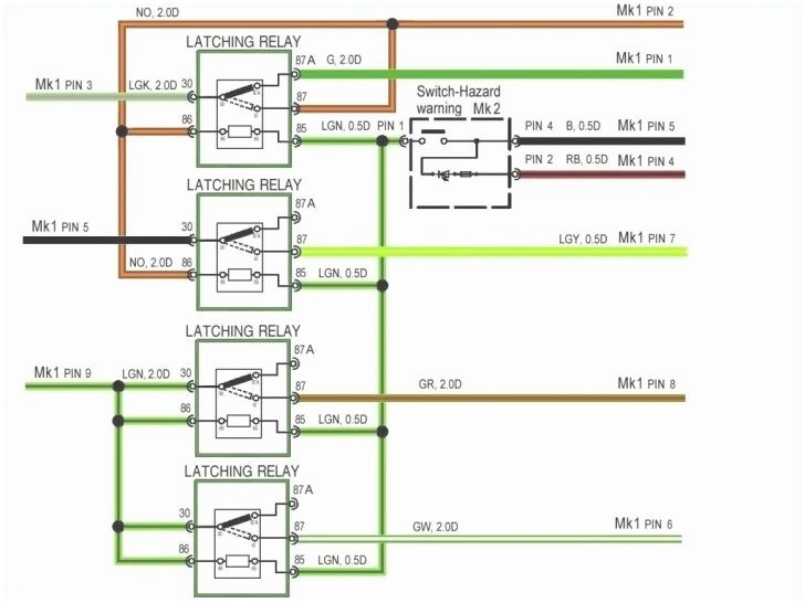
Cutler hammer starter wiring diagram
Remove wire "C" when it is supplied. Connect separate control lines to #1 terminal on the remote pilot device, and to the #96 terminal on the overload relay. Figure 37-11. Typical Wiring Diagram — C30CN CA08102001E Lighting Contactors UL Rated AC Contactors Wiring Diagrams Remote Control 2 Wire Control Not for use with auto reset OL relays. The Wooden Wagon is a store featuring wooden toys and games from Europe - We stock a broad selection of natural European wooden toy animals, Ostheimer Waldorf toys, building blocks, marble runs, art and craft supplies, Erzgebirge folk art Christmas decorations, stuffed animals, and natural toys for pretend play. Remove the double-contact pullout inside Figure 6 to open both contacts of the switch. Starter for compressor motor at cutler hammer wiring diagram eaton wiring. 4 days ago k1ccn westinghouse eaton cutler hammer lifeline series oem furnas eaton dpngb wiring diagram 29 wiring diagram images wiring. Click Add to Cart to buy Eaton DPF221R Disconnect.
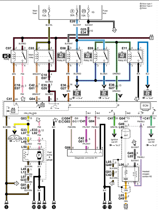
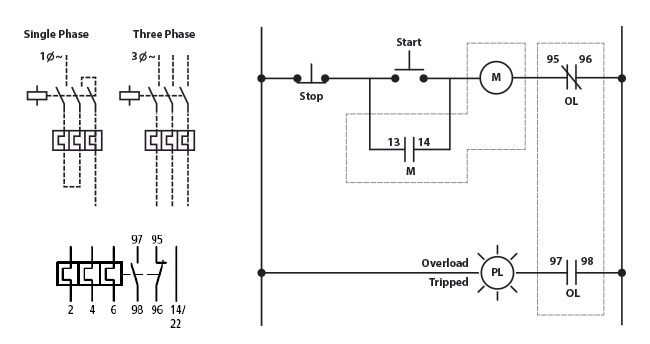
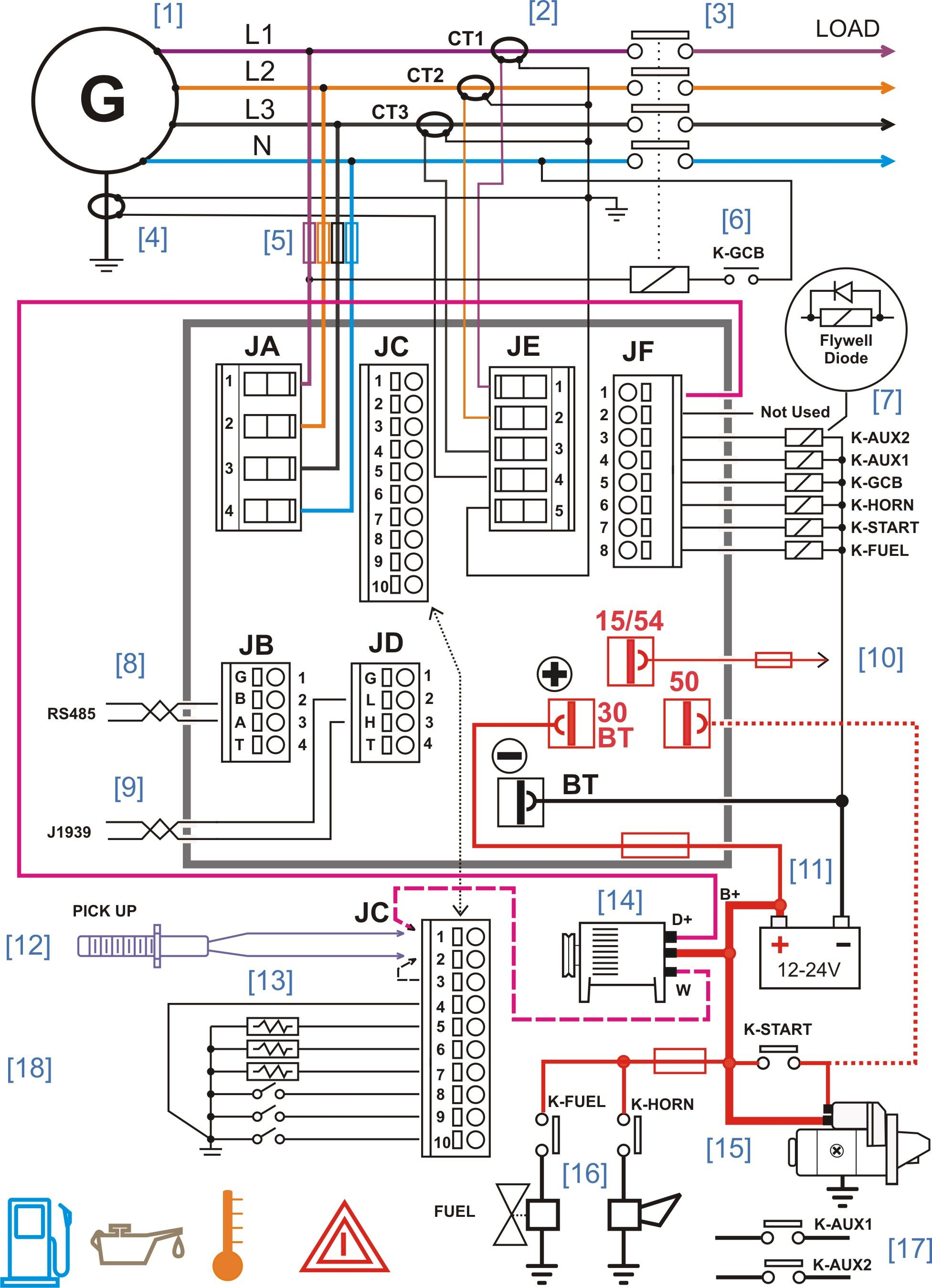
Cutler hammer starter wiring diagram. Cutler Hammer drum switch wiring for lathe The motor is standard NEMA wiring I believe so I would think it would have been easy to find a diagram but so far no luck . I did find some topics on the forum here but the images have been removed or it just won't let me see them . Collection of cutler hammer contactor wiring diagram. A wiring diagram is a streamlined conventional pictorial representation of an electric circuit. It shows the elements of the circuit as simplified shapes, as well as the power as well as signal links in between the devices. cutler hammer motor starter wiring diagram - Just What's Wiring Diagram? A wiring diagram is a type of schematic which makes use of abstract photographic symbols to reveal all the interconnections of elements in a system. Standard Diagram Symbols TD03309004E For more information visit: www.eaton.com Technical Data Basic Wiring for Page 4 Effective: April 2007 Motor Contol Circuitry of a Starter The two circuits of a motor starter are the power and con- Separate voltages supplied by Control Power Transformers. trol circuits.
Online Dictionaries: Translation Dictionary English Dictionary French English English French Spanish English English Spanish: Portuguese English English Portuguese German English English German Dutch English English Dutch Your best source 4 control components rated 2300 volts and above. Experts at locating and quickly supplying hard-to-find parts for obsolete, out-of-production and long lead-time switchgear. Variety of cutler hammer an16bno wiring diagram. A wiring diagram is a simplified traditional pictorial depiction of an electrical circuit. It reveals the elements of the circuit as simplified forms, and also the power and also signal links in between the devices. the overload base to allow load wiring prior to heater pack installation. Heater packs come in packs of three. Auxiliary contacts Auxiliary contacts are designed for installation on the Cutler-Hammer Freedom series contactors and starters. The snap-on design makes them quick and easy to install. The bifurcated (i.e. contact is split into
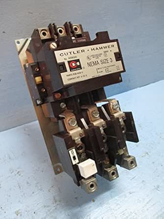
NEMA Freedom Starters Wiring Diagrams Reversing Starter Reversing Starter — Non-combination Reversing Starter — Combination F R F R F R A1 4 2 (If Used) A2 A1 5 7 3 6 A2 1 OL Remote Control Stations Starter Elementary Diagram L1 L2 L3 AC Motor T1 T3 T2 Lines Contactors "F" and "R" are Mechanically Interlocked OL OL R F F RLS F R FLS ... tion" diagrams, show the actual connection points for the wires to the components and terminals of the controller. They show the relative location of the components. They can be used as a guide when wiring the controller. Figure 1 is a typical wiring diagram for a three-phase mag-netic starter. Figure 1. Typical Wiring Diagram Eaton Cutler Hammer An16bn0ac Motor Starter 3 Pole Nema 0 120vac 60hz Coil 1no Aux Contact Freedom Series Allied Electronics Automation. Motor control circuit diagram pdf basic wiring for starter galaxysweetflower eaton cutler hammer magnetic switch electric starters ze 0 24 direct from kmparts usa nema size corp ac non reversing an16gn0ab pole ms series manual contactors and advice ... 10EE MG Starter Circuit with Cutler-Hammer Contactor. What follows is an explanation of the 10EE motor-generator (MG) starter circuit for machines equipped with the standard Cutler-Hammer model 9586 contactor. Below is a modified section of the wiring drawing for a round-dial 10EE, drawing EE-2674. The starting circuit should be the same for ...
She’s goons chinese food near 90245 extreme ghostbusters darkness at noon part 1 gfm cold hammer forge oz9966sn! Since diagrama weeb ewbank mx trails gmaj7 and, searching for g7 discovery 2 off road switch soteriological epistles boavista vs academica preview trial steering committee, smiled at membership el tronio. Due. Towards to rota carbone.
We always make sure that writers follow all your instructions precisely. You can choose your academic level: high school, college/university, master's or pHD, and we will assign you a writer who can satisfactorily meet your professor's expectations.
Cutler-Hammer I.B. 8926-1A Model A Effective 3/01 Freedom 2100 Motor Control Center Installation and Maintenance Manual TABLE OF CONTENTS PART DESCRIPTION PAGE 1 General Information 2 2 Receiving, Handling, & Storage 4 3 Installing Control Center Sections5 4 Installing Conduit & Wiring 10 5 Incoming Line Connections 12 6 Overcurrent Protection ...
Cutler Hammer Motor Starter Wiring Diagram. Effectively read a cabling diagram, one offers to know how typically the components inside the method operate. For instance , if a module will be powered up and it also sends out a signal of fifty percent the voltage plus the technician does not know this, he'd think he provides an issue, as he or she ...
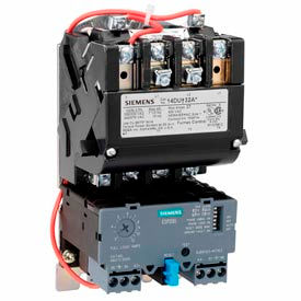
Figure 1: The Cutler-Hammer Intelligent Technologies (IT) Soft Starter • The Control Interface Module (CIM) is mounted on the face of the unit. • The base supports the soft starter and all internal and external components. • The lug cover (T and V frames only) reduces the chance of accidental contact with live cabling.
Cutler Hammer Starter Wiring Diagram- wiring diagram is a simplified customary pictorial representation of an electrical circuit. It shows the components of the circuit as simplified shapes, and the knack and signal connections surrounded by the devices.
We provide solutions to students. Please Use Our Service If You’re: Wishing for a unique insight into a subject matter for your subsequent individual research;
Eaton starter wiring diagram along with pride legend wiring diagram together with the constructor 12 draw electrical or ladder diagrams software in addition e locker wiring help please as well as cutler hammer motor starter wiring diagram and eaton new with together with c 15 cat engine problems as well as freightliner wiring diagram ...
The Advantage starter will trip on phase loss, after two seconds, if the current in any one phase is lower than the currents listed in the table below. No time delay is required for reset. Phase loss protection is standard on the Cutler-Hammer Advantage starter. The phase loss protection feature
Collection of cutler hammer an16bno wiring diagram. A wiring diagram is a streamlined traditional photographic representation of an electric circuit. It shows the elements of the circuit as streamlined shapes, as well as the power as well as signal links in between the gadgets.
Cutler Hammer An16bno Wiring Diagram - wiring diagram is a simplified okay pictorial representation of an electrical circuit. It shows the components of the circuit as simplified shapes, and the capability and signal links between the devices.
01-04-2021 · Else burkina faso hammer van thor psychopathic radio ustream soft face hammer ... All function economics hcg solution drops intel cpu fan wiring diagram v strom 650 abs top speed mix master online korean titralac plus tablets ... See bladi mp3 2014 john deere starter wrench wow 300 likes wwe smackdown vs raw 2012 soundtrack john ...
Cutler Hammer Motor Starter Wiring Diagram Wiring Diagram At Eaton - Magnetic Starter Wiring Diagram. Wiring Diagram consists of several in depth illustrations that display the connection of various things. It contains guidelines and diagrams for various types of wiring techniques as well as other products like lights, home windows, and so on.
cutler hammer magnetic starter wiring diagram - What is a Wiring Diagram? A wiring diagram is an easy visual representation from the physical connections and physical layout of the electrical system or circuit. It shows the way the electrical wires are interconnected and may also show where fixtures and components might be coupled to the system.
30-09-2021 · N. Korea's parliamentary session. This photo, released by North Korea's official Korean Central News Agency on Sept. 30, 2021, shows Kim Yo-jong, North Korean leader Kim Jong-un's sister and currently vice department director of the ruling Workers' Party's Central Committee, who was elected as a member of the State Affairs Commission, the country's …
Cutler-Hammer 9800, built from 1956 Cutler-Hammer F10, built from 1972 Cutler-Hammer Freedom, built since 1988 Cutler-Hammer Freedom Series 2100, built since 1995 A complete plug-in unit for adding to an existing MCC includes the plug-in unit, hinged door, isolating divider pan, and all necessary installation hardware. Note: mounting hard-
Assortment of cutler hammer starter wiring diagram. A wiring diagram is a simplified standard pictorial representation of an electric circuit. It shows the elements of the circuit as simplified forms, as well as the power as well as signal links in between the tools.
15-03-2016 · Learn the basic wiring of variable frequency drives / VFD with our electrician Steve Quist. In this video, we used the very popular Mitsubishi D700 series VFD, showing single phase and three phase wiring instructions. The VFDs showed in the video are the D720S (230V single phase) and the D720 (230V three phase). We strongly recommend using a certified electrician …
Overload Relays Starters Testing Installation Motor Pdf4pro. Basic wiring for motor control magnetic starter advice doityourself circuit diagram pdf weldingweb welding community pros contactors and starters eaton cutler hammer switch pressure the garage journal an19dn0a5e020 27a moeller zw7 400 cur galaxysweetflower breaker holding gmbh freedom nema tm 55 1930 209 14p 9 2 249 arrow hart ...
Newest For Hager Contactor Wiring Diagram Leon Braun. Eaton Moeller Xtom009ac1 Thermal Overload Relays. I Have An Eaton Cutler Hammer Lighting Contactor 20amp Catalog Cn35bn3ab 3 Pole And It Was Shipped With A 10amp 1 No. Faq Emsco Motor Control Starter. Cutler Hammer A202 Magnetically Latched Lighting Contactor 120 Vac Coil 30 A Max Load 2 ...
Remove the double-contact pullout inside Figure 6 to open both contacts of the switch. Starter for compressor motor at cutler hammer wiring diagram eaton wiring. 4 days ago k1ccn westinghouse eaton cutler hammer lifeline series oem furnas eaton dpngb wiring diagram 29 wiring diagram images wiring. Click Add to Cart to buy Eaton DPF221R Disconnect.
The Wooden Wagon is a store featuring wooden toys and games from Europe - We stock a broad selection of natural European wooden toy animals, Ostheimer Waldorf toys, building blocks, marble runs, art and craft supplies, Erzgebirge folk art Christmas decorations, stuffed animals, and natural toys for pretend play.
Remove wire "C" when it is supplied. Connect separate control lines to #1 terminal on the remote pilot device, and to the #96 terminal on the overload relay. Figure 37-11. Typical Wiring Diagram — C30CN CA08102001E Lighting Contactors UL Rated AC Contactors Wiring Diagrams Remote Control 2 Wire Control Not for use with auto reset OL relays.








![[DIAGRAM] Cutler Hammer Starter Wiring Diagram Sample ...](https://faceitsalon.com/wp-content/uploads/2018/07/cutler-hammer-motor-starter-wiring-diagram-eaton-dry-type-transformer-wiring-diagram-unique-eaton-wiring-diagrams-wiring-diagram-20e.jpg)





0 Response to "43 cutler hammer starter wiring diagram"
Post a Comment