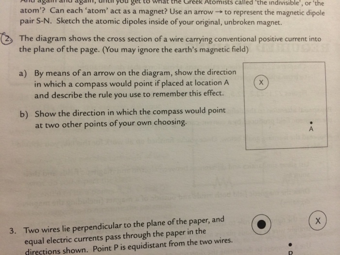
44 the diagram shows the cross section of a wire carrying conventional positive current
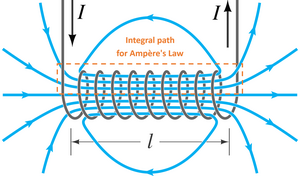
Dec 24, 2012 · The wheel carrying the lifting mechanism for the hammers is usually placed in the early stages of the striking train as there is more power avail able there. ... A positive, reliable shutoff ... A long straight wire carrying a 6.0 A current enters a room through a window 2.0 m high and 1.5 m wide. The path integral around the window frame has the value (in T m): 18. 5.0 × 10 -7 3.8 × 10 -6 7.5 × 10 -6 none of these. A long straight cylindrical shell carries current i uniformly distributed over its cross section.
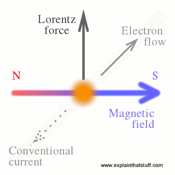
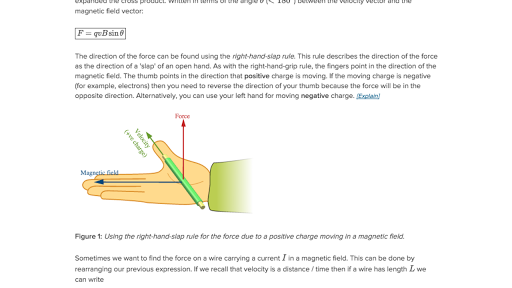
Wire between two magnets. The diagram shows a straight wire carrying a flow of electrons out of the page. The wire is between the poles of the permanent magnet. The direction of the magnetic force exerted on the wire is: Please Note: My diagram isn't perfect but both magnets are the same size and the wire is equidistant from both of the magnets.

The diagram shows the cross section of a wire carrying conventional positive current
From Biot-Savart law, the magnetic field from a small segment of current carrying wire proportional to *(GK ̂ where ̂ is a unit vector from current carrying segment to P. Using the right hand rule, the cross product points into the page. 9. The diagram shows three equally spaced wires that are perpendicular to the page. The The figure shows three long, parallel current-carrying wires. The magnitudes of the currents are equal and their directions are indicated in the figure. Which of the arrows drawn near the wire carrying current 1 correctly indicates the direction of the magnetic force acting on that wire? The electron drift speed in a typical current-carrying wire is Reading Question 27.2 ... Establishing the Electric Field in a Wire The figure shows two metal wires attached to the plates of a charged capacitor. This is an ... The electric field strength Electron Current E in a wire of cross-section A causes an electron current:
The diagram shows the cross section of a wire carrying conventional positive current. D.C.CIRCUIT CONCEPTS & CIRCUIT ELEMENTS . Enter the email address you signed up with and we'll email you a reset link. 2. The diagram below represents a conductor carrying conventional current in magnetic field B. The direction of the magnetic force on the conductor is (A) into the page (C) toward the top of the page (B) out of the page (D) toward the bottom of the page 3. The diagrams below show cross sections of conductors with conventional current flowing ... 24. The diagram shows the cross-sections of two current carrying wires. The direction of the force on the right-hand wire due to the current in the left-hand wire is (A) to the right (B) to the left (C) upward in the plane of the page (D) downward in the plane of the page (E) into the page 25. Force on current carrying wires F qv B v v v Since B-fields exert forces on moving = × charges, it is natural that B-fields exert forces on current carrying wires. How do we quantify this force in terms of current I, instead of q and v? Area A Length vector L + Velocity v Consider the wire shown below. Now add a Magnetic Field. X B Force F qv ...
diagram below, a wire carrying an conventional current into the page, as denoted by X, is placed in a magnetic field. A)C B)D C)A D)B The magnetic field exerts a force on the wire toward point 9.Base your answer to the following question on The diagram below shows an end view of a straight conducting wire, W, moving with constant speed in The figure shows a cross section of three parallel wires each carrying a current of 24 The currents in wires B and C are out of the paper, while that in wire A is into the paper If the distance R = 511 mm, what is the magnitude of the force on a 40-m length of wire A? b. 15 77 59 mN 12 32 mN Along cylindrical wire (radius = If n electrons pass through the cross-section of a conductor in time t, the total charge that passes through the conductor is then, Q = n×e. Electric Current and Circuit Diagram Elements. The schematic diagram represents the different components of a circuit; this is the circuit diagram. These symbols represent the common electrical components. cross-section of a conductor in time t, the total charge that passes through the conductor is then, Q = n×e. Electric Current and Circuit Diagram Elements The schematic diagram represents the different components of a circuit; this is the circuit diagram. These symbols represent the common electrical components.
Nov 24, 2019 · Pins" (main menu -> View) shows anchor boxes on the schematic when a label is moved. Creating a Label when doing a .op Simulation. When doing a DC operating point simulation (.op) an operating point data label can be created as follows Run the .op simulation; Left-Click on a net (a wire). This creates a new label that can be placed with the cursor. Since the wire is so small, the coil can have thousands of turns and still fit in the slots. The small-gauge wire cannot handle as much current as the heavy-gauge wire in the series field, but since this coil has many more turns of wire, it can still produce a very strong magnetic field. Figure 12-14 shows a picture of a DC shunt motor. The changing current in the solenoid produces a changing flux in the loop. By Lenz's law there will be an induced current and field to oppose the change in flux. We assume that the solenoid is long enough such that there is not field outside the solenoid, and therefore the flux through the cross section of the solenoid is the flux through the ... We will now look at three examples of current carrying wires. For each example we will determine the magnetic field and draw the magnetic field lines around the conductor. Magnetic field around a straight wire (ESBPT) The direction of the magnetic field around the current carrying conductor is shown in Figure 10.1.
Jun 10, 2021 · Electrochemical impedance spectroscopy (EIS) is a powerful tool to investigate properties of materials and electrode reactions. This Primer provides a guide to the use of EIS and a comparison with ...
Two long, straight, current-carrying wires are parallel to each other in the plane of the page and separated by a distance a, as shown above. The direction of the current I in each wire is toward the top of the page. Which of the following best represents the force per unit length acting on the wires.
Ensure you request for assistant if you can’t find the section. When you are done the system will automatically calculate for you the amount you are expected to pay for your order depending on the details you give such as subject area, number of pages, urgency, and academic level. After filling out the order form, you fill in the sign up details. This details will be used by our support …
Our cheap essay writing service has already gained a positive reputation in this business field. Understandably so, since all custom papers produced by our academic writers are individually crafted from scratch and written according to all your instructions and requirements. We offer APA, MLA, or a Chicago style paper in almost 70 disciplines. Here, you can get quality custom …
01.10.2019 · Unplug the key. Remove marked 3 nichrome wire from the gap XY. Connect the copper wire marked 4 having same length and same area of cross-section as that of nichrome wire marked 1. . Plug the key again and note the ammeter reading. It measures the current (I 4) through copper wire. Repeat the experiment with iron wire and measure the current (I 5).
24.10.2015 · Abloom has a square cross section 150 mm (6 in) or larger. A slab is rolled from an ingot or a bloom and has a rectangular cross section of width 250 mm (10 in) or more and thickness 40 mm (1.5 in) or more. A billet is rolled from a bloom and is square with dimensions 40 mm (1.5 in) on a side or larger. These intermediate shapes are subsequently rolled into final …
A. power dissipated in a wire of known length, cross-sectional area and resistivity. B. potential difference across a resistance of known value. C. number of electrons flowing past a point in a circuit in a given time. D. force per unit length between parallel current-carrying conductors.
In this diagram, the solid teal circle in the center represents a cross-section of a current-carrying wire in which the current is coming out of the plane of the paper. The concentric circles surrounding the wire's cross-section represent magnetic field lines.
Force on a Current-Carrying Wire. The force on a current carrying wire (as in ) is similar to that of a moving charge as expected since a charge carrying wire is a collection of moving charges. A current-carrying wire feels a force in the presence of a magnetic field. Consider a conductor (wire) of length ℓ, cross section A, and charge q ...
You can entrust all your academic work to course help online for original and high quality papers submitted on time. We have worked with thousands of students from all over the world. Most of our clients are satisfied with the quality of services offered to them and we have received positive feedback from our clients.
The diagram shows the cross section of wire carrying conventional positive current into the plane of the page. (You may ignore the earth's magnetic field) A) By means of an arrow on the diagram, show the direction in which a compass would point if placed at location A and describe the rule you use to remember this effect.
The diagram shows the cross section of wire carrying conventional positive current into the plane of the page. (You may ignore the earth's magnetic field) A) By means of an arrow on the diagram, show the direction in which a compass would point if placed at location A and describe the rule you use to remember this effect.
Calculating Forces on Wires Two wires, both carrying current out of the page, have a current of magnitude 5.0 mA. The first wire is located at (0.0 cm, 3.0 cm) while the other wire is located at (4.0 cm, 0.0 cm) as shown in . What is the magnetic force per unit length of the first wire on the second and the second wire on the first?
Current I is the rate at which charge moves through an area A, such as the cross-section of a wire. Conventional current is defined to move in the direction of the electric field. (a) Positive charges move in the direction of the electric field and the same direction as conventional current.
A current in a wire or circuit element can flow in either of ... In conductors where the charge carriers are positive, conventional current is in the same direction as the charge carriers. In a vacuum, a beam of ions or electrons may be formed. In other conductive materials, the electric current is due to the flow of both positively and negatively charged particles at the same time. …
Diagram showing the cross-section of a linear motor cannon Full-scale models have been built and fired, including a 90 mm (3.5 in) bore, 9 megajoule kinetic energy gun developed by the US DARPA . Rail and insulator wear problems still need to be solved before railguns can start to replace conventional weapons.
24. A long, straight wire carries 20 A. A 5.0-cm by 10-cm rectangular wire loop carrying 500 mA is located 2.0 cm from the wire, as shown in Fig. 30-53. Find the net magnetic force on the loop. Solution At any given distance from the long, straight wire, the force on a current element in the top segment cancels
Voltage increases as we cross the battery, whereas voltage decreases as we travel across a resistor. The ... If the arrow is in the opposite direction of the conventional current flow, the result for the current in question will be negative but the answer will still be correct. The number of nodes depends on the circuit. Each current should be included in a node and thus included in …
The conventional "hole" current is in the negative direction of the electron current and the negative of the electrical charge which gives I x = ntw(−v x)(−e) where n is charge carrier density, tw is the cross-sectional area, and −e is the charge of each electron.
0 Full PDFs related to this paper. READ PAPER. Mechanics of Materials 9th edition
Cross section of a single Hall element; an N-type epi resistor contacted in each of the four corners. As mentioned earlier, when a current is forced from one corner of the plate to the opposite corner, a Hall voltage will develop across the other two corners of the plate when in the presence of a perpendicular magnetic field. The Hall voltage will be zero when no field is …
The diagram shown in Figure 31.7 shows a metallic strip carrying a current in the direction shown and placed in a uniform magnetic field with the direction of the magnetic field being perpendicular to the electric field (which generates the current I).
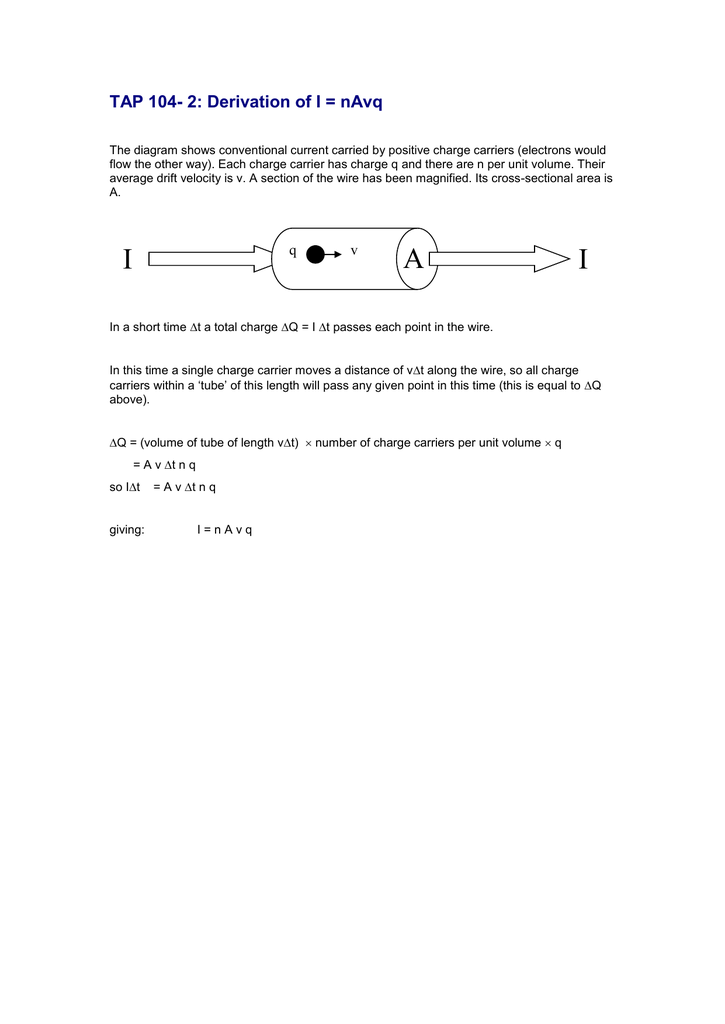
The diagram in Figure 1 shows a simplified and enlarged view of a section of a wire carrying a current. The electrons are in random motion but if a potential difference is applied across the wire with the right hand end positive the free electrons drift slowly towards that end. schoolphysics: Electric current animation
1. (0/6 Points] DETAILS PREVIOUS ANSWERS M A copper wire with square cross section carries a conventional current I in the -x direction. There is a magnetic field B in the +z direction. Draw a diagram illustrating the situation, to help you answer the following questions.
30. The speaker in the diagram below makes use of a current-carrying coil of wire. The N-pole of the coil would be closest to (1) A (3) C (2) B (4) D 31. In the diagram below, A, B, C, and D are points near a current-carrying solenoid. Which point is closest to the north pole of the solenoid? (1) A (3) C (2) B (4) D 32. If the current through a ...
A long straight wire lies on a table and carries a current I. A small circular loop of wire is pushed across the top of the table from position 1 to 2. Determine the direction of the induced current (clockwise OR counter-clockwise) as the loop moves past (A) position 1 and (B) position 2. Explain in complete detail. Table top
We always make sure that writers follow all your instructions precisely. You can choose your academic level: high school, college/university, master's or pHD, and we will assign you a writer who can satisfactorily meet your professor's expectations.
As depicted in the diagram below, the current in a circuit can be determined if the quantity of charge Q passing through a cross section of a wire in a time t can be measured. The current is simply the ratio of the quantity of charge and time. Current is a rate quantity. There are several rate quantities in physics.
The electron drift speed in a typical current-carrying wire is Reading Question 27.2 ... Establishing the Electric Field in a Wire The figure shows two metal wires attached to the plates of a charged capacitor. This is an ... The electric field strength Electron Current E in a wire of cross-section A causes an electron current:
The figure shows three long, parallel current-carrying wires. The magnitudes of the currents are equal and their directions are indicated in the figure. Which of the arrows drawn near the wire carrying current 1 correctly indicates the direction of the magnetic force acting on that wire?
From Biot-Savart law, the magnetic field from a small segment of current carrying wire proportional to *(GK ̂ where ̂ is a unit vector from current carrying segment to P. Using the right hand rule, the cross product points into the page. 9. The diagram shows three equally spaced wires that are perpendicular to the page. The









0 Response to "44 the diagram shows the cross section of a wire carrying conventional positive current"
Post a Comment