44 solenoid valve diagram how to understand
8" Nugget solenoid operated valve. This valve does not have provisions for an external pilot supply which is required for "Normally Open" solenoid operated valves. Three-way valve applied to a spring return cylinder. Three-way Valves Three-way valves are the same as 2-way valves with the addition of a third port for exhausting downstream air. in this video we are describe about pneumatic connection diagram of solenoid valve 3/2 and 5/2 , and practical explanation in this video.pls follow us socia...
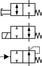
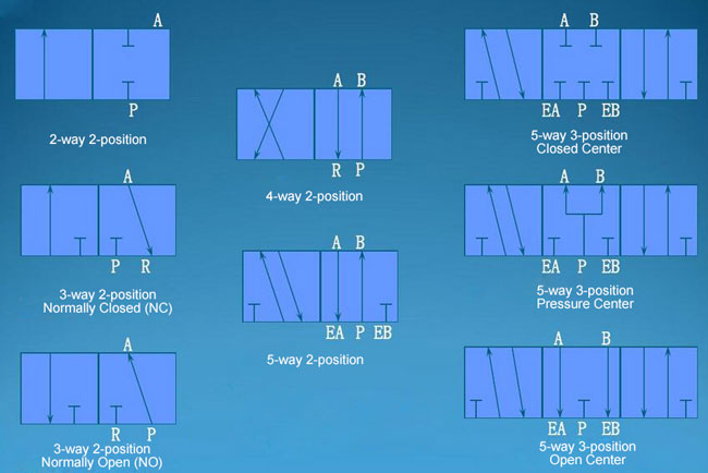
Understanding schematic symbols will help to better understand at a glance the application, control, direction, amount of flow for actuated valves, cylinders and rotary actuators. Basic Symbols. Square or rectangular block specify a valve position.
Solenoid valve diagram how to understand
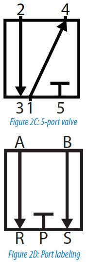
Understanding Pneumatic Schematics Symbols for Sliding Solenoid Valves Return Spring indicates the Position of the solenoid valve at rest. Triangle Symbols indicate output or exhaust port B In this position Port A Is being exhausted through Arrows indicate exhaust port EA. direction of gas flow through the valve and ports ENGINEERING FLUIDS DIAGRAMS AND PRINTS To read and understand engineering fluid diagrams and prints, usually referred to as P&IDs, an individual must be familiar with the basic symbols. EO 1.1 IDENTIFY the symbols used on engineering P&IDs for the following types of valves: a. Globe valve g. Relief valve b. Gate valve h. Rupture disk 21 Mar 2016 — The number of 'position and flow boxes' that make up a valve symbol indicate the number of valve positions. Flow direction is indicated by the ...
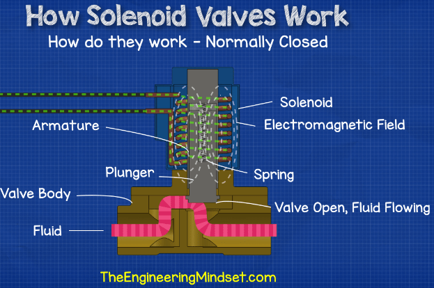
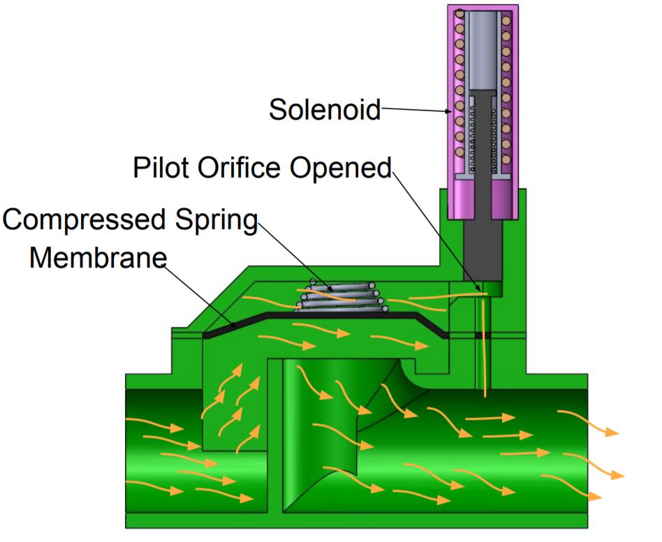
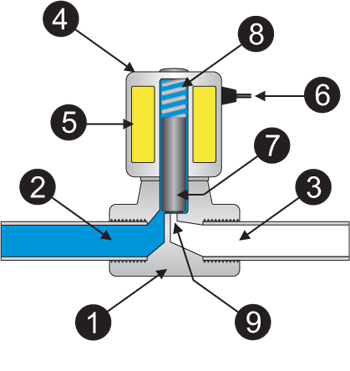
Solenoid valve diagram how to understand. A solenoid valve is a combination of two basic functional units: • A solenoid (electromagnet) with its core • A valve body containing one or more orifices Flow through an orifice is shut off or allowed by the movement of the core when the solenoid is energized or de-energized. ASCO valves have a solenoid mounted directly on the valve body. The The solenoid valve symbols are the schematic diagram used to describe functions of the solenoid valve. The schematic diagram is usually applied to the pneumatic system design and product identifications for pneumatic system designers and solenoid valve users to get a thorough understanding of product functions. Solenoid Valve - How They Work. A solenoid valve is an electrically controlled valve. The valve features a solenoid, which is an electric coil with a movable ferromagnetic core (plunger) in its center. In the rest position, the plunger closes off a small orifice. An electric current through the coil creates a magnetic field. Let's get started. 1. Identifying the line types. In a hydraulic schematic, each line type has a unique meaning. In addition, colors can be added to indicate purpose of the line. In the figure below, all of the basic line types are shown. The basic line is a solid line that represents a working pressure hose or tube.
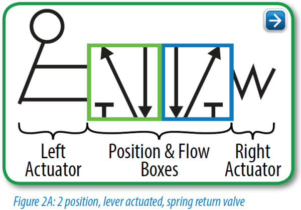
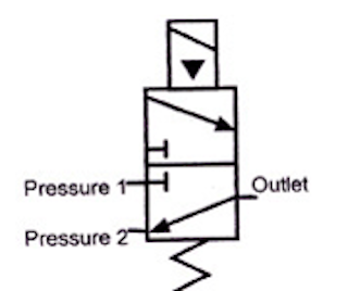
• Understand how DHOLLANDIA diagrams are set up • Be able to recognize the used symbols, and making the link with the "real world" • Understand how the principle valves, etc… work in theory Original: 26/06/2007 ˘Last update: 24/04/2008 The spring symbol defines the “at Rest” position of the solenoid valve. The spring “pushes” from the side it is drawn on and places the right side block diagram of the valve in function. The T Symbol This symbol indicates that a port is closed and is neither passing or exhausting gas. Pressure of air supply symbol Directional valves continue to use the square envelopes, as is seen by the 2/2 poppet valve and 4/3 solenoid valves shown. Each envelope—or square—represents one of the possible positions of the valve. The 2/2 poppet doesn't specify how the valve shifts, but that it will block flow in one position, and allows flow in the other. All leaflets are available on: www.asco.com 42 - General & Engineering Information ISO 1219 symbols - SOLENOID AND PRESSURE-OPERATED VALVE TECHNOLOGY ports/positions function control return symbol (1) 3/2 U (universal) solenoid spring 2 13 NC solenoid air
The 2-position and 3-port pneumatic solenoid valve can be divided into the normally-closed mode and the normally-open mode. The 3/2-way pneumatic solenoid valve is usually used together with the single-acting pneumatic actuator, and adopts the single electric control, namely the single coil. The coil voltage grade generally adopts DC 12V, DC ... The solenoid is placed over this and completely surrounds the armature so that it's at the centre of its magnetic field. Inside the cylinder of the armature is the plunger and spring. How normally closed solenoid valves work. The spring pushes the plunger down in a normally closed type valve. Because the plunger is pushed by the spring, it ... The envelope that a solenoid operator is attached to is the position that the valve spool will move to when that solenoid is energized. The handle operator means that the valve can be manually operated. Spring operators indicate that the valve spool will return to its center position if there is nothing actively driving it to a different position. 1 A solenoid is a simple form of an electromagnet consisting of a coil of insulated copper wire. A solenoid valveis an electromechanical valve frequently used to control the flow of liquid or gas. Definitions Solenoid valves are found in many applications and are commonly used in refrigeration and air conditioning systems.
The structure of the high-speed switching solenoid valve ...
The number of ports a valve has is shown by the number of endpoints in a given box. We should only count the ports in a single box once per symbol. For example, in the 3-position valve, there are three boxes that show the three possible positions, but the valve has five physical ports. So the valve will be called a 5/3 solenoid valve.
Solenoid Valves | Solenoid Solutions
solenoid valves and the 180 solenoid pilot control...and all solenoid valves in the field that are equipped with the old style KC-2 coil. When changing from the old KC model coils to the current MKC * E34, B33, E33 and E42 are obsolete. * OE34, OB33, OE33 and OE42 are obsolete. Solenoid Valves Installation and Servicing Instructions SD-15/52021
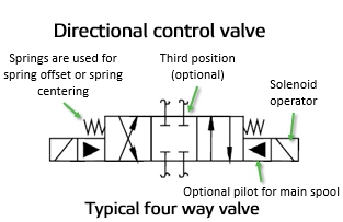
Directional Valve Symbols
General Information:Valve Construction And Basic Operation. A solenoid valve is an electronically operated device. It is used to control the flow of liquids or gases in a positive, fully-closed or fully-open mode. The valve is commonly used to replace a manual valve or where remote control is desirable.

Pin on Cool stuff
In this tutorial we will be controlling a solenoid with an Arduino and a transistor. The solenoid we have picked for this tutorial is our Plastic Water Solenoid Valve (perfect for controlling flow to a drip irrigation system) but this tutorial can be applied to most inductive loads including relays, solenoids, and basic DC motors.

Best-Practice for Choosing an Air Solenoid Valve – Numatic ...
The difference between the two valve types is the number of exhaust ports: A 5/2-way pneumatic valve has two independent exhaust ports. A 4/2-way valve has only one common exhaust port. Valve symbol of a mono-stable 4/2-way valve with ISO and alternative port designation. This means that both port (A,2) and (B,4) connect to exhaust port (R,3).
What is the function of a solenoid valve in an HVAC system ...
The solenoid draws a continuous current of 700mA when energised and a peak of nearly 1.2A so we have to consider these things while designing the driver circuit for this particular Solenoid valve. Circuit Diagram. The complete circuit diagram for Solenoid driver circuit is shown in the image below. We will understand why it is designed so, once ...
How Solenoid Valves Work - The Engineering Mindset
solenoid operated valve. This valve does not have provisions for "Normally Open" solenoid operated valves. N.O. 2-WAY. SYMBOL. ACTUATED. POSITION.

How sprinkler solenoid valves work - Make:
ground, and at solenoid on valve in valve box. • Could be a bad solenoid (very rare). • Check to see if the water main is on. (top) These are most of the reasons why a valve is not working properly. If you have the opportunity, take a valve apart and match the parts to the attached diagram. This diagram is for Hardie / Irritrol ®
BOOK 2, CHAPTER 14: Proportional control valves | Power & Motion
Solenoid valves are electrically operated devices used to control flow. They are used for the remote on/off or directional control of liquids, gases and steam. They do not regulate flow. Solenoid valves consist of two main elements: 1.) An electrical coil in the solenoid, and 2.) A valve body or pressure vessel. The solenoid is the electromagnetic

Solenoid Valves | SafeRack's Industrial Index
solenoid valve. The spring "Pushes" from the side it is drawn on and places the right side block diagram of the valve in function. The Arrows The Arrow symbols illustrate the direction of gasses flowing into and out of the valve ports. Gas is pressure is supplied from port P. De pending on which of the valve blocks is in function, the gas is

HOW TO READ A SPOOL VALVE SCHEMATIC DRAWING
Solenoid wiring typically is a simple, two-wire system consisting of power feed and return wires connected to the solenoid coil, interrupted at some point by a control circuit trigger mechanism. … A solenoid consists of a single electrical component, namely its coil.

Direct-Acting Solenoid Valve Animation | Valve, Directions ...
How to Read Pneumatic Schematic Symbols.... The block . ... The spring symbol defines the "at rest" position of the solenoid valve. The spring "Pushes" from the side it is drawn on and places the right side block diagram of the valve in function. The T Symbol.
WHAT IS A SOLENOID VALVE? - Valtorc International
Most equipment requires either a 12V or 24V (volt) DC circuit.Understanding the ANSI symbols and manufacturer's flow diagrams ensures the proper valve is specified. Normally Close (NC) or Normally Open (NO) When designing a direct-acting solenoid valve as part of a fluid control system, the process begins with the flow in a de-energized mode.
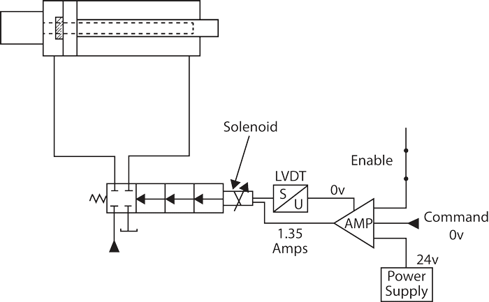
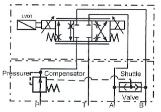
Understanding and Troubleshooting Hydraulic Proportional Valves
3 Way Solenoid Valves Control Instrument Air Pressure Control Systems Engineering P Id Diagram Programmable Logic Controllers . Objective To Understand The Basic Concept Of On Off Valve Using A Plc Target Users Students Technicians Ladder Logic Programmable Logic Controllers Valve ... Honeywell 3 Port Valve Wiring Diagram Heating Systems ...

Cross section of the solenoid valve. | Download Scientific ...
21 Mar 2016 — The number of 'position and flow boxes' that make up a valve symbol indicate the number of valve positions. Flow direction is indicated by the ...

How do you control 1 solenoid valve from 2 sources? | All ...
ENGINEERING FLUIDS DIAGRAMS AND PRINTS To read and understand engineering fluid diagrams and prints, usually referred to as P&IDs, an individual must be familiar with the basic symbols. EO 1.1 IDENTIFY the symbols used on engineering P&IDs for the following types of valves: a. Globe valve g. Relief valve b. Gate valve h. Rupture disk

Heat Pump Reversing Valve
Understanding Pneumatic Schematics Symbols for Sliding Solenoid Valves Return Spring indicates the Position of the solenoid valve at rest. Triangle Symbols indicate output or exhaust port B In this position Port A Is being exhausted through Arrows indicate exhaust port EA. direction of gas flow through the valve and ports

On-Off Solenoid For Hydraulic Solenoid Valves | Kaidi

How to wiring DC solenoid valve with 3 wire - General ...

5/2 & 4/2-Way Pneumatic Valve - How They Work | Tameson.com

What is a 3-way Solenoid Valve ? | Instrumentation Tools
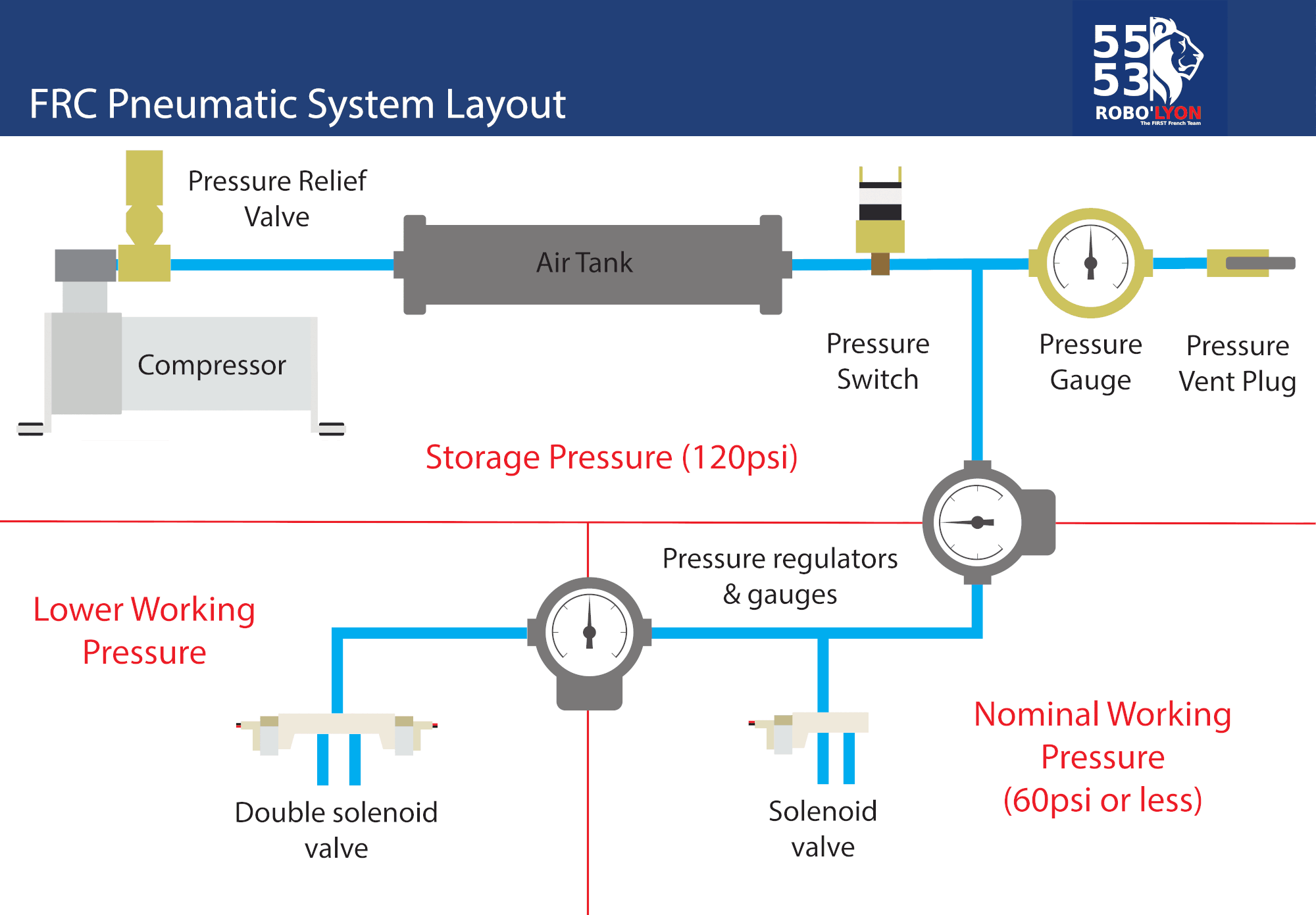
FRC Pneumatic System Diagram - Control System - Chief Delphi
Can you explain a solenoid valve with a diagram? - Quora

Solenoid Valve Symbols
Reading fluids circuit diagrams - hydraulic & pneumatic symbols
Solenoid Valve Symbols
STC 2S025-050 Series Solenoid Valves
What is Solenoid Valve and How does a Solenoid Valve Work?

How to Read a Spool Valve Schematic Drawing - RealPars

How to Read and Interpret Piping and Instrumentation Diagrams ...
Pneumatic Circuit Symbols Explained |Library.AutomationDirect
Pneumatic Circuit Symbols Explained |Library.AutomationDirect

Assalamualaikum....Welcome home...: How to Read Pneumatic ...

How to Read a Spool Valve Schematic Drawing - RealPars
BOOK 2, CHAPTER 8: Directional Control Valves | Power & Motion

Miniature Motors for Valve Actuation

How Solenoid Valves Work - The Engineering Mindset

Comparison of Normally Open Solenoid Valve and Normally ...

How to Read a Spool Valve Schematic Drawing - RealPars
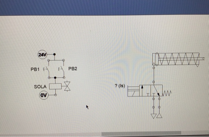
OBJECTIVES DESCRIPTION Understand the control of a | Chegg.com
Solenoid Valve Basics

CHAPTER 10: Directional Control Valves, part 4 | Power & Motion

Solenoid valve - Wikipedia

How Solenoid Valve Works? Parts of Solenoid Valves - Bright ...
0 Response to "44 solenoid valve diagram how to understand"
Post a Comment