43 3 phase phasor diagram
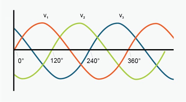
PDF Phasors Final 3 9 2012 Ron Alexander.ppt - Aventri •Phasor diagrams require a circuit di agram. The phasor diagram… has a indeterminate or vague meaning unless it is accompanied by a circuit diagram. •The assumed directions and polarities are not critic al, as the phasor diagram will confirm if the assumptions were correct, and provide the correct magnitudes and phase relations. PDF Three Phase Theory - Professor J R Lucas A balanced three phase supply can be connected either in star as in figure 2 (a) or in delta as in figure 2 (b). Figure 1(a) - Three phase waveforms VR VB VY Figure 1(b) Phasor Diagram N VR VB VY Figure 2(a) Star-connected supply IP IL VP VL VRY VYB VBR Figure 2(b) Delta-connected supply Id IL VL
Excel Phasor Diagram Builder - Eaton Corporation Click to select either diagram, and select File->Print. Only the selected diagram will print. If you are wanting to publish these diagrams, print to a PDF format and then refer to this other article on how to extract the diagram in a scalable vector format suitable for typesetting. I've also added a 3-phase phasor diagram builder.
3 phase phasor diagram
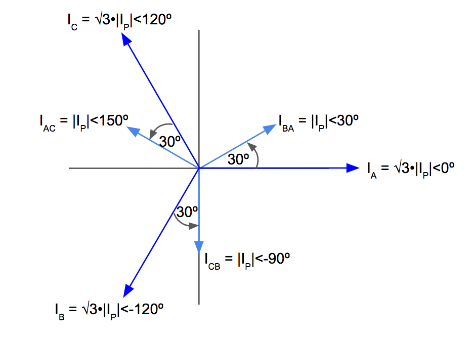
Phasor Diagram - an overview | ScienceDirect Topics Time phasor diagrams for one phase winding under no-load and loaded conditions are shown in Fig. 9.17 A and B, respectively, and in each case the time phasors of the flux linkage have been shifted to the right to avoid congestion with the voltages and current.These flux phasors can be compared with the space vectors shown in Fig. 9.10.Once again, resistance has been neglected in the interests ... PDF BALANCED THREE-PHASE CIRCUITS - Mississippi State University Given a balanced three-phase system, the currents flowing into the delta-connected load can be defined by The resulting phasor diagram relating the line currents to the delta-connected load currents follows the same pattern as the delta-connected source. PDF EE411 Balanced Three Phase Phasors - Baylor University Balanced three-phase systems, no matter if they are delta connected, wye connected, or a mix, are easy to solve if you follow these steps: 1. Convert the entire circuit to an equivalent wye with a grounded neutral. 2. Draw the one-line diagram for phase a, recognizing that phase a has one third of the P and Q. 3.
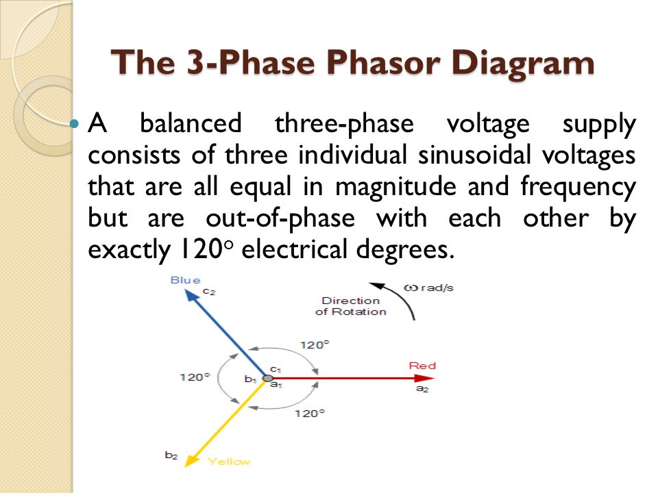
3 phase phasor diagram. Phasor Diagram and Phasor Algebra used in AC Circuits Three-phase Phasor Diagram The phase voltages are all equal in magnitude but only differ in their phase angle. The three windings of the coils are connected together at points, a 1, b 1 and c 1 to produce a common neutral connection for the three individual phases. Equivalent circuit and Phasor diagram of synchronous motor Phasor diagram of synchronous motor A 3-phase cylindrical rotor synchronous motor may operate at different power factors i.e., lagging, unity or leading. Accordingly, its phasor diagram is drawn with the help of the above equations. Before going into the section, learn how the synchronous motor behaves at no-load and load conditions. PDF Lesson 4: Three Phase Sources and Loads Construct phasor diagrams of three-phase sources and loads. Identify the time and phasor plots of a three phase set of voltages and currents. 2/4/2016 2 Double Subscript Notation 3 Lesson 4_et332b.pptx Sources and voltage drops are defined by the terminal letter. Voltage drop How to use a phasor diagram? - Fluke Phasor diagram display The most powerful tool on Fluke's three phase analyzers to make this check is the phasor diagram display. In one screen, you can quickly see whether you have connected up the voltage and current in the right sequence and that the current sensors are correctly measuring the direction of the current entering the load or ...
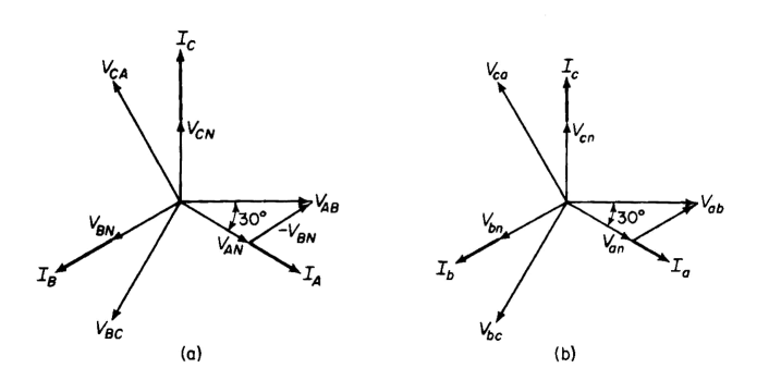
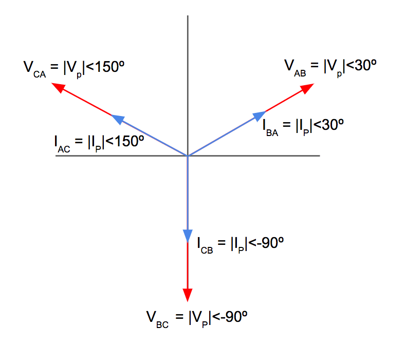
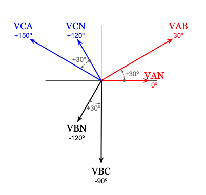
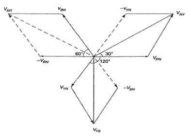
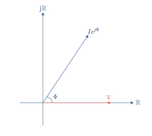
Three-Phase The key to understanding three-phase is to understand the phasor diagram for the voltages or currents. In the diagram at the right, a, b and c represent the three lines, and o represents the neutral. The red phasors are the line or delta voltages, the voltages between the wires. The blue phasors are the wye voltages, the voltages to neutral. If a 1-Phase Supply is 230V, Why is 3-Phase 400V & Not 690V? The vector addition based on the phasor diagram for 3-ϕ supply system, where each line has 230V, the vector difference is almost 400V for each phase (either Phase 1 & Phase 2, Phase 2 and Phase 3 or Phase 3 and Phase 1). Phase Sequence in Three-Phase System - Electrical Academia When we are given the line voltage and phase sequence of a three-phase source, as in Figure 2 (a), we can draw a phasor diagram by placing one phasor (usually VBA) along the reference axis. As we read clockwise around the phasor diagram of Figure 2 (b), all the first subscript letters of the voltage phasors must follow the specified phase sequence. Phasor Diagram and Phasor Addition - Electrically 4 U Phasor Diagram and Phasor Addition. Phasor Diagram is a graphical representation of the relation between two or more alternating quantities in terms of magnitude and direction. In other words, it depicts the phase relationship between two or more sinusoidal waveforms having the same frequency. Phasor is a straight line with an arrow at one end ...
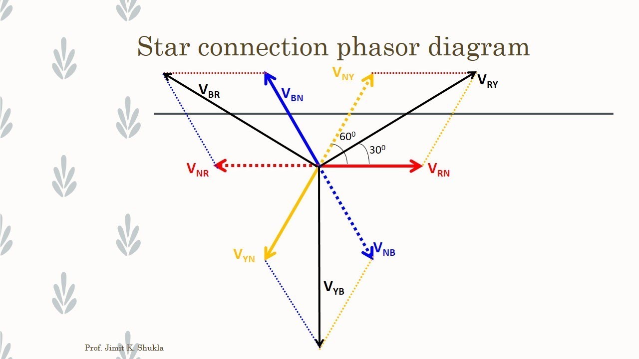
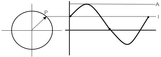
Generation of 3 Phase Power in 3 Phase ... - Circuit Globe Generation of 3 Phase E.M.Fs in a 3 Phase Circuit Phasor Diagram In 3 phase circuits (balanced load), the power is defined as the sum of various powers in a three-phase system. i.e. Power in star connections in a 3 phase circuits is given as The phase voltage and line voltage in the star connection is represented as shown below: Phasor Diagram Creator Online - Wiring Diagrams The phase of an alternating quantity at any instant in time can be represented by a phasor diagram, so phasor diagrams can be thought of as "functions of time". A complete sine wave can be constructed by a single vector rotating at an angular velocity of ω = 2πƒ, where ƒ is the frequency of the waveform. What is a Star Connection in 3 phase? - Theory & Phasor ... What is a Star Connection in 3 phase? - Theory & Phasor Diagram. In this system three similar ends of the phase windings are connected at one point which is known as the star point or neutral point. The remaining three ends are brought out for supply this supply system is known as three phase four wires supply system as shown in Fig. 16.5. Three phase electric power and phasor diagrams explained ... Electricity and Three phase power: Voltage and current "Line to Neutral", "Line to Line", and Phasor Diagrams. My Patreon page is at ...
Three Phase AC Star Circuit Phasor Diagram
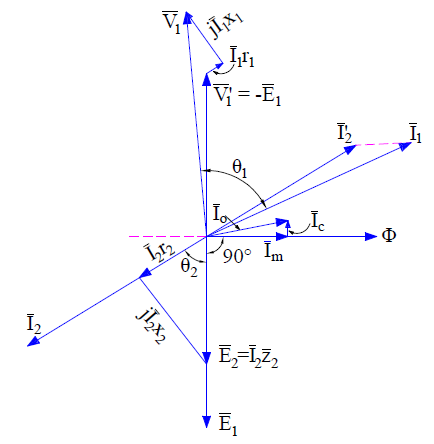
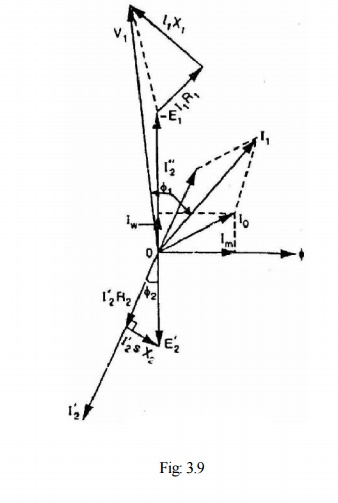
3. Phasor diagram.pdf - PHASOR DIAGRAM of a LOADED ... PHASOR DIAGRAM of a LOADED TRANSFORMER Phasor diagram is drawn with reference to exact equivalent circuit. In any phasor diagram, the different phasors are represented by their magnitude and direction with reference to a reference phasor. Let V 2 - Secondary terminal voltage be taken as the reference phasor since load parameters are measurable and well defined. 3

Equivalent Circuit of a Three Phase Induction Motor - My Tech ...
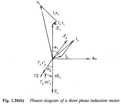
Phasor Diagram of Three Phase Induction Motor - BrainKart Phasor Diagram of Three Phase Induction Motor In a 3-phase induction motor, the stator winding is connected to 3-phase supply and the rotor winding is short-circuited. The energy is transferred magnetically from the stator winding to the short-circuited, rotor winding.
Induction Motor Phasor Diagram - Electrical Concepts
Phasor Diagrams - Learn About Electronics Phasor Diagrams Show Phase Difference. A phasor diagram is used to show the phase relationships between two or more sine waves having the same frequency. Section 5.2 showed a phasor continually rotating, but in use phasor diagrams are static. Imagine that the phasors are rotating in an anticlockwise (counter clockwise) direction.
Wye-Wye Connection
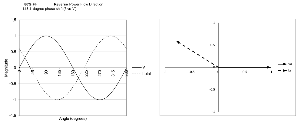
(PDF) Phasor Diagram Analysis for Non-Salient Pole ... It The Figure-2 shows the leading phasor diagram happens when the current and voltage are in phase. For of power factor. It happens when the current are lead the this phasor diagram the value of the theta is zero. That voltage. It will make the current waveform are comes first means the the value of the ᴪ = δ.

Phasor Diagram and Phasor Algebra used in AC Circuits
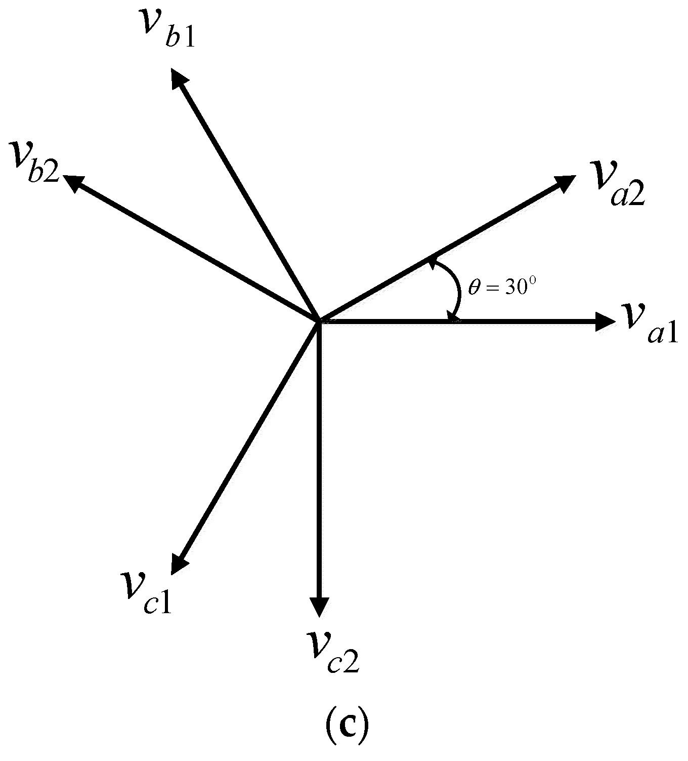
Easy understanding of 3-phase transformer connections ... Three-phase voltage transformations can be accomplished by using 3-phase transformers, which are single devices with all windings constructed on a single. Search for: ... The phasor diagram at the lower right shows the geometric relationships between the high voltage circuit and low voltage circuit currents, ...

induction motor equivalent circuit and phasor diagrams
What is 3 phase Star Delta Connection explain with phasor ... A phasor diagram is used to show the phase relationships between two or more sine waves having the same frequency. A phasor diagram is one in which the phasors, represented by open arrows, rotate counterclockwise, with an angular frequency of ω about the origin. Post navigation.
Lesson 4: Three Phase Sources and Loads
Three Phase AC Star Circuit Phasor Diagram - YouTube 3-Phase AC star circuit phasor diagram drawing steps to remember. Formula of relation between phase and line voltage and current.There is a mistake in the eq...
Three Phase Delta Connection: Three Phase Power,Voltage ...
Three Phase Transformer Connections Phasor Diagrams ... A three-phase transformer is built for a specific connection and voltage transformation and the unit will have a nameplate with the internal connections shown. When a single unit or bank of three is used, there are four types of connections. The four basic connections are: Y-Y, Y-∆, ∆-Y, and ∆-∆. The first symbol indicates the connection of the primary, and the second symbol is the ...
Open Delta Transformer Connection - Electrical PE Review
Delta Connection in a 3 Phase System - Relation between ... As in the balanced system the three-phase current I 12, I 23 and I 31 are equal in magnitude but are displaced from one another by 120° electrical. The phasor diagram is shown below: Hence, If we look at figure A, it is seen that the current is divided at every junction 1, 2 and 3. Applying Kirchhoff's Law at junction 1,
An Introduction to Using Phasor Diagrams on Oscilloscopes for ...
Phasor diagram of the three phase system | Download ... Assuming balance three phase supply connected to an unbalance three phase load, the voltages and currents at the load end can be written as shown in (1). Fig. 1 shows the corresponding phasor ...

Electrical Phasor Diagrams | Electrical Academia
PDF Experiment3 Three Phase AC Circuits Objectives Theory Three Phase AC Circuits Objectives - To apply three phase AC circuit using lab-volt device in the lab practically and simulation using (LVVL) program. - To be familiar how can be connection star and delta load and the difference between them. - Using the phasor diagram and oscilloscope window to show the relationship between the currents
The Complete Guide to the Square Root of Three in Power ...
PDF EE411 Balanced Three Phase Phasors - Baylor University Balanced three-phase systems, no matter if they are delta connected, wye connected, or a mix, are easy to solve if you follow these steps: 1. Convert the entire circuit to an equivalent wye with a grounded neutral. 2. Draw the one-line diagram for phase a, recognizing that phase a has one third of the P and Q. 3.
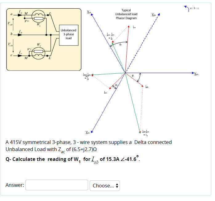
Solved a-b- t Typical Unbalanced load Phasor Diagram | Chegg.com
PDF BALANCED THREE-PHASE CIRCUITS - Mississippi State University Given a balanced three-phase system, the currents flowing into the delta-connected load can be defined by The resulting phasor diagram relating the line currents to the delta-connected load currents follows the same pattern as the delta-connected source.
Phasor Diagrams and Phasor Algebra Md Shahabul Alam Dept. of ...
Phasor Diagram - an overview | ScienceDirect Topics Time phasor diagrams for one phase winding under no-load and loaded conditions are shown in Fig. 9.17 A and B, respectively, and in each case the time phasors of the flux linkage have been shifted to the right to avoid congestion with the voltages and current.These flux phasors can be compared with the space vectors shown in Fig. 9.10.Once again, resistance has been neglected in the interests ...
E&C: LESSON 21. Voltage, Current and Power in a Star and ...

Phasor Diagram and Phasor Algebra used in AC Circuits
Open Delta Transformer Connection - Electrical PE Review

3: Three-phase voltages shown in a phasor diagram. | Download ...
THREE PHASE NETWORKS

Why do phasor diagrams for a 3-Phase High-Leg Delta systems ...
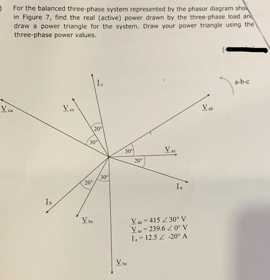
Solved For the balanced three-phase system represented by ...
Phasor Diagram of Three Phase Induction Motor

Phasor diagram illustrating the compensation mechanism of the ...

3-Phase AC Calculations Revisited - Dataforth
Characteristics of Three Phase Induction Motor
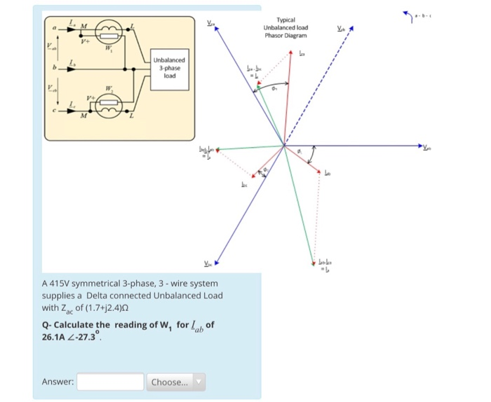
Solved Typical Unbalanced load Phasor Diagram 3-phase load A ...

Review of three-phase systems
Phasors and Phasor Algebra

Phasor diagram showing the balanced three-phase fluxses A,B,C ...

Phasor diagram of three phase system | Download Scientific ...

Phasor diagram of the three phase system | Download ...

A balanced, three-wire, star-connected, 3-phase load has a ...

Voltage and Current Phasors in Three-Phase Systems ...

Phasor Diagram for star connection
Phasor Diagrams and Phasor Algebra - Electronics-Lab.com
Excel Phasor Diagram Builder

Three Phase Star Connection (Y): Three Phase Power,Voltage ...

3-Phase AC Calculations Revisited - Dataforth
Equivalent Circuit And Phasor Diagram Of 3 Phase Induction ...

Phasor Diagram and Phasor Algebra used in AC Circuits
Electronics | Free Full-Text | Systematic Implementation of ...
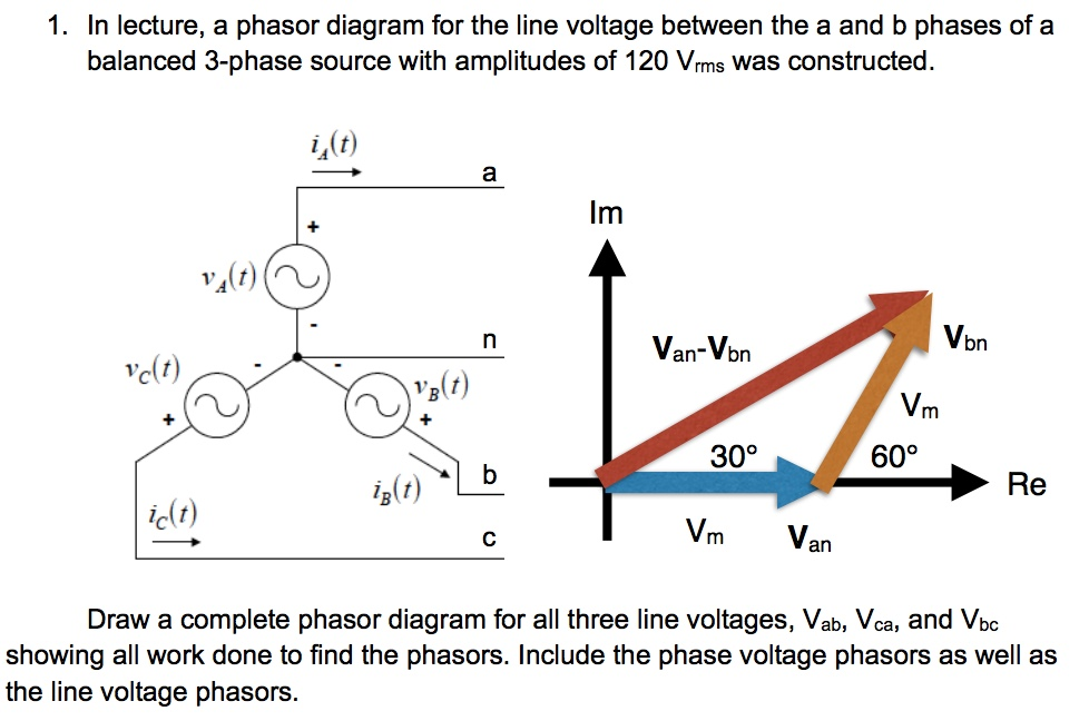
Solved 1. In lecture, a phasor diagram for the line voltage ...

Learn | OpenEnergyMonitor
0 Response to "43 3 phase phasor diagram"
Post a Comment