44 6.5 glow plug controller wiring diagram
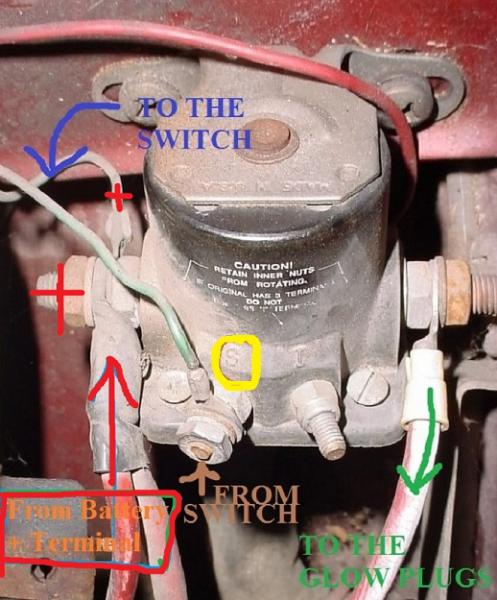
Bad glow plugs most probably or the glow plug controller. to check your glow plugs remove wire and check with ohm meter to ground. if they are working you should get a low ohm reading if one has a high ohm the controller click when you turn the key to on. Does the wait to start light come on? ... ww17.aprsca.net/led-light-to-12-volt-battery.jpg" alt="Led Light To 12 Volt Battery Wiring Diagram" /> ... 6.5 Glow Plug Controller Wiring Diagram
How to test the glow plugs, glow plug controller and the fuseable links.

6.5 glow plug controller wiring diagram
1 I have 11v Autolite glow plugs 2 I have 4 relays with normally open, normally closed, and common terminals 3 I have a push button switch that has power with 6 The GP controller is connected to the relay's NC terminal 7 Wires from the battery's plus terminal are connected to the relay's NO terminal. Glow plug relay wiring diagram ford truck 7 3l idi manual controller system troubleshooting easy one 1999 2003 control schematic no signal to the 88 3 ... Controller photo above doesn't apply to this truck either. Of the wires on the two small terminals, the insulation color notwithstanding, one comes After tearing apart some plastic wiring cases, I found the wire in question (indicated on the diagram) and it comes off the GP relay and plugs directly into the...
6.5 glow plug controller wiring diagram. All 6 glow plug failure means that it us your glowplug control unit that is faulty. Unless all 6 have infact failed, but I'd eat my hat if they have! So, I had this problem with my 330d too not so long ago, but I'm buggered if I can point you to its location! Download Full Version! Download 1hz Glow Plug Wiring Wiring Diagram Filled in: Wiring Diagram 1hz Glow Plug Wiring Wiring Diagram 9 out of 10 based ... Wiring Diagram - Wiring Diagram Dec 10, 2017Vv 9030 2003 Duramax Glow Plug Relay Diagram Free. 6 5 glow plug controller wiring 6l duramax relay location on a 2004 chevy lb7 diagram 3 posts dreaded p0380 after replacing 2 sel place 03 code performance 2001 9 2003 merchant gm control... ... glow plug wiring harness wiring diagram 7 ... 7.3 Glow Plug Relay Wiring Diagram 7 3 Glow Plug Relay Wiring Diagram Fresh Diagram for 6 5 Diesel Glow
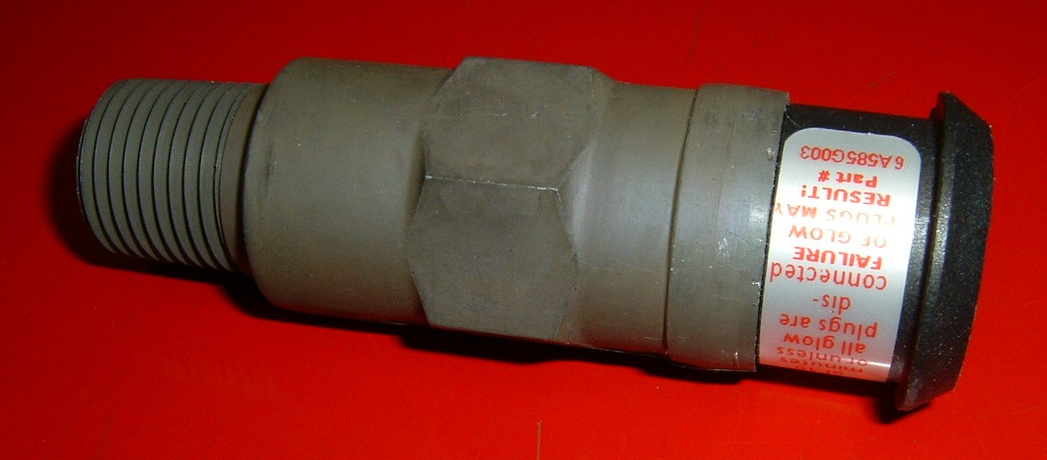
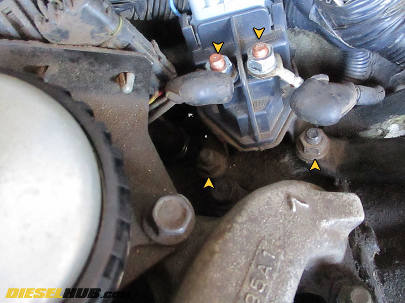
Download Full Version! Download 1hz Glow Plug Wiring Wiring Diagram Filled in: Wiring Diagram 1hz Glow Plug Wiring Wiring Diagram 9 out of 10 based ... Electrical wiring diagrams for Audi A6 C5/4B Avant (Audi A6. Read cabling diagrams from bad to positive in addition to redraw the circuit being a straight collection. All circuits usually are the same ~ voltage, ground, single component, and switches. 6.5 Glow Plug Controller Wiring Diagram Source: www.dieselplace.com. If the glow plug system works with the connector wires jumped, the inhibit switch needs to be replaced or bypassed. If there is high resistance or no continuity between any individual glow plug wire and the output terminal of the glow plug controller, that glow plug's fusible link has likely failed.
Cheap essay writing sercice. If you need professional help with completing any kind of homework, Solution Essays is the right place to get it. Whether you are looking for essay, coursework, research, or term paper help, or with any other assignments, it is no problem for us. Download Full Version! Download 1hz Glow Plug Wiring Wiring Diagram Filled in: Wiring Diagram 1hz Glow Plug Wiring Wiring Diagram 9 out of 10 based ... Note: Be very careful when connecting wires from the power cord to the power supply! Since we are working with AC voltage, incorrect wiring could cause a serious shock or fire. Do NOT plug the power cord into a wall outlet while performing the steps below. On the power cord, strip the insulation back until you see white, black, and green wires. Cheap essay writing sercice. If you need professional help with completing any kind of homework, Custom Scholars is the right place to get it. Whether you are looking for essay, coursework, research, or term paper help, or with any other assignments, it is no problem for us.
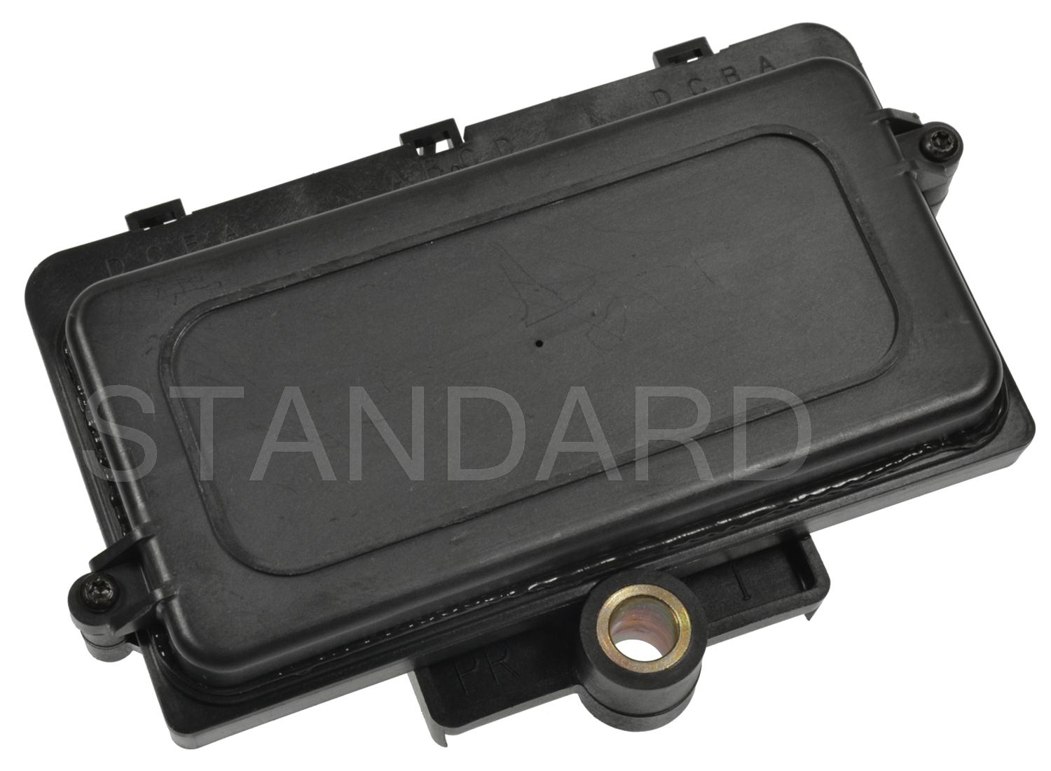
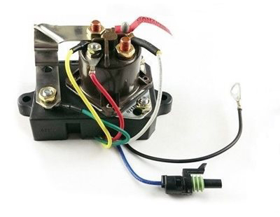
Diesel Glow Plug Controller Relay 1994-2002 6.5L Chevy ...
Glow Plug Controller - Free download as PDF File (.pdf), Text File (.txt) or read online for free. glow. known as glow plug. A control circuit is necessary to optimise the functioning of glow plugs. It raises the air temperature inside the engine cylinder for quick and reliable starting, extended battery...

Wood-N-Things - Glow Plug System
so next I tested the plug wire to check for voltage with the ignition on, and nothing. Keep in mind the car was hot at this point, I had driven several miles Focus on the harness and plug on the Glow Plug Controller. Take it off and check the pins inside the plug with your multi-meter. Pin 7 is ground, pin 8...

94-01 GM 6.5 Diesel RX Glow Plug Relay / Controller DRX01006 ...
Page 214: Glow Plug 12. Electrical System 12.8 Glow plug A glow plug is available for warming intake air when starting in cold areas in winter. The glow plug is M4 x 0.7 mounted to the cylinder head. The device is operated by the glow switch on the instrument panel. Rated current 8-10A Rated voltage... Page 215: Electric Engine Stopping Device 12.
GM Diesel Hummer Glow Plug Operation, Testing & Troubleshooting
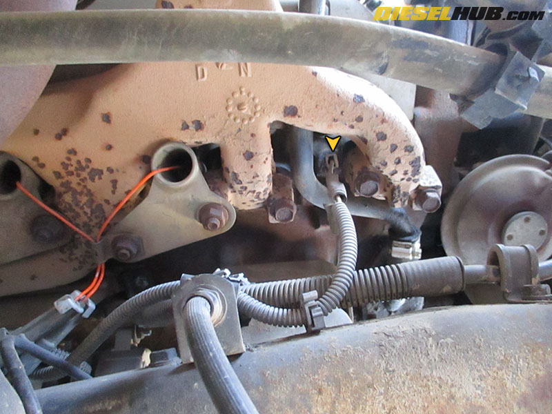
...the plug and controller swap, so i figured the glow plug was causing the misfire. Ran codes again Cylinder 5 Glow plug circuit Oxides of nitrogen sensor circuit I'll take a pic and diagram it if anyone wants, otherwise that's all I can think of for intake manifold is coming off again and I'll be looking for a wiring issue I guess.
6.2 Glow Plug Relay Mod | Chevy and GMC Duramax Diesel Forum
Glow Plug Controller. In diesel engines, the air in the cylinders is not hot enough to ignite the fuel Connect the glow plug wire to the relay contact. 12V battery already available with the vehicle is 2. Glow Plug Controller. Pin Configuration: Component Required: R1, 220 ohm R2, 1.5M ohm R3, 15K...

1994 Chevy 6.5 Turbo diesel has no glow plug light and will ...
6.5 glow plug controller wiring? Jump to Latest Follow. On my 2000 6.5 the glow plug controller has two terminals, one goes into the truck wiring harness and the other to the glow plugs - I am leaving out the big plug here because that was obvious to hook up.

Wiring Harnesses – www.blackhorse-racing.com
Apr 29, 2021 - Beru Glow Plug Controller Wiring Diagram . I Need Wiring Diagrams for 2001 for F150 4 2l V6 Yes solenoid Starter Rebuilt Yes 2001.
Glow Plugs Don't Stay On - Hilux Surf & 4Runner forum
The wiring diagrams are grouped into individual sections. If a component is most likely found in a par-ticular group, it will be shown complete (all wires, connectors, and pins) within that group. Glow plug relay (diesel). Controller anti-lock brake.

Experimental study of using biogas in Pulse Detonation Engine ...
...circuit diagram SOLAR POWER CONTROLLER(SDRC) USER MANUAL Characteristics: Control circuit: use MCU and professional software as the control center to fulfill Cut the wire. c. Connect the wire to the battery port on the controller to the battery. Pay attention to the +, - pole of the connection.
6.2L Early Glow Plug Controller (1982 - 1984)
6265 glow plug controller diagram i need a wiring diagram for 6265 glow plug controller cars trucks question. 1994 turbo diesel. Wiring Glow Plug Controller Great Installation Of Wiring Diagram. Glow Plug Controller Relay 92 93 Ssdiesel Supply Gm 6 5 Td.
Glow plug relay clicks/buzzes loudly | Diesel Place
The glow plug controller (Fig. 1) uses a simple timer circuit built around MOSFET T1 for reliability and simplicity. Momentary pushing of switch S2 charges capacitor C1 rapidly Assemble the circuit on any general-purpose PCB and house in a suitable case. Connect the glow plug wire to the relay contact.

Ford 7.3L IDI Glow Plug Relay Testing Procedure
Filled in: Wiring Diagram Glow Plug Controller Override System Wiring Diagram 9 out of 10 ratings. ... Diagram Glow Plug Controller Override System ...

12v Aust HJ75 Wilson switch install question | IH8MUD Forum
Controller Wiring Diagram Check that the four-wire connector at the controller is seated properly and latched . Tighten the 1: Glow plug system #5 · Dec 11, 2009. on the drivers side there should be a wire on the front and rear glowplug and a rail from the front across each of them to the rear. on the...

Harness for ssd-139 Glow Plug Controller :: SSDiesel Supply ...
6.5TD C/K Trucks > Glow Plugs & Controllers > Harness Pigtail for ssd-1005 Glow Plug Controller ... Early year 6.2 glow plug controllers are now ...
6.2 Glow Plug Relay Mod | Chevy and GMC Duramax Diesel Forum
I've checked the glow plug fuse and the guages fuse, as the chilton diagram shows it on the pink wire circuit... thanks in advance! i have a 94 yukon with the 6.5 in it i was wondering if you knew where the pcm is in it and how to test it or a site to look up.
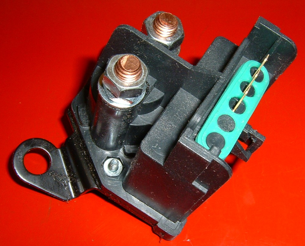
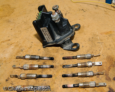
6.5L Glow Plug Controller (1994-2002)
WIRING DIAGRAM A wiring diagram shows, as closely as possible, the actual location of all A wiring diagram is limited in its ability to completely convey the controller's sequence of operation. Examples of Control Circuits 3-Wire Control Elementary Diagrams. Jogging: Selector Switch and...

7.3L IDI Manual Glow Plug Controller wiring diagram ...
A glow plug indicator is made for seconds with a margin up to several minutes or maybe longer. Solution: A piece of stainless steel wire that Solution: Use 8.5V glow plugs instead of 12V glow plugs. Life span: Probably 2 decades, maybe more but in the end (20+ years) the controller will burn...
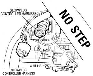
Glowplug Controller Harness Schematic
Filled in: Wiring Diagram 7 3 Idi Glow Plug Controller Wiring Diagram Wiring Diagram 9 out of 10 based on 90 ratings.

84 6.2 replaced controller, glow plugs, glow plug relay ...
Manual glow plug relay solenoid for chevy gm 62 and 65. Browse categories answer questions. 7 3 Idi Engine Diagram Schemati...

Glow plug wiring
Dealer replaced three glow plug control modules, within a three month time, before replacing two complete wiring Apparently, two glow plugs were shorted causing wiring harness failure. You may want to get your glow plugs checked...
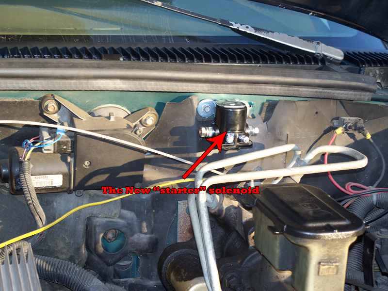
6.2L & 6.5L GM, Detroit Diesel Glow Plug Controller Replacement
Never plug or unplug any device while the printer is powered. In addition to being a safety hazard, it Below is a circuit diagram with more details. Endstop Wiring. Endstops can be wired one of two Follow the links to the wiring configuration guides specific to your printer and controller selection.
Fuse issues with glow plugs - Diesel Bombers
This is the glow plug control module unit to raise the air temperature inside the engine cylinder for quick and reliable starting, to extend the battery life and Connect the glow plug wire to the relay contact. The 12V battery source that already available with the vehicle can be used to power the circuit.

glow plug relay test, how? | The Diesel Stop
Replacing your old Glow Plug Controller is recommended when you change your glow plugs. Diesel Power Products carries Diesel RX's full line of parts. The best way to determine which style you need is by the connection of the wire harness to the glow plug.
Temeraturfühler H1
6.2 Glow Plug Controller Wiring Diagram Oct 09, 201810 10 0 Comments on 6.2 Glow Plug Controller Wiring Diagram Check that the four-wire connector at the controller is seated properly and latched . Tighten the 1: Glow plug system schematic, (L). Related searches for 6 5 diesel glow plug...
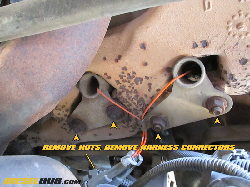
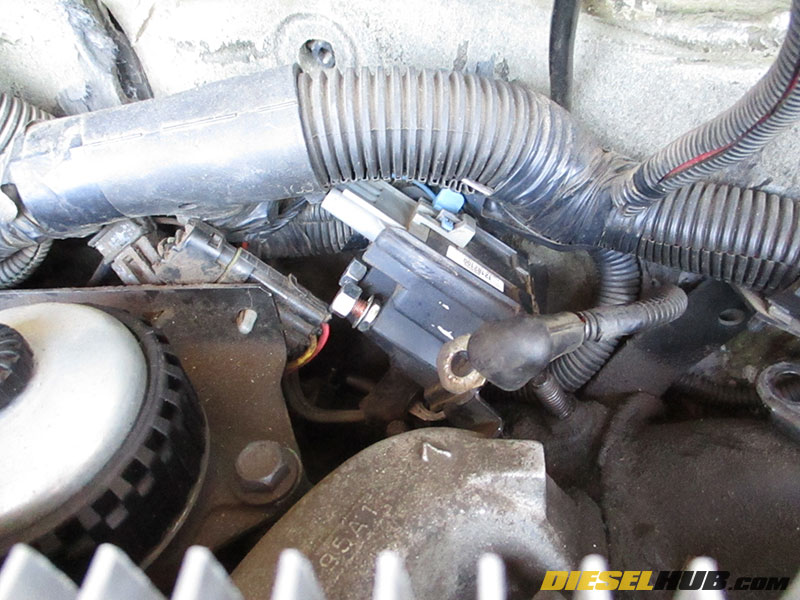
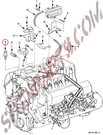
6.5L GM Diesel Glow Plug Replacement Procedures
... 23 2021 In Wiring Diagram 222 views Lly Duramax Glow Plug Controller Location 418 5 183 votes Top Suggestions Lly Duramax Glow Plug Controller ...
Diesel Glow Plug Controller
Mitsubishi-Triton-L200-Workshop-Manual-2006-2013
wiring diagram for stock Glow plug system (93) | Diesel Place
Controller photo above doesn't apply to this truck either. Of the wires on the two small terminals, the insulation color notwithstanding, one comes After tearing apart some plastic wiring cases, I found the wire in question (indicated on the diagram) and it comes off the GP relay and plugs directly into the...

Very early glow plug wiring | Defender Source Forum
Glow plug relay wiring diagram ford truck 7 3l idi manual controller system troubleshooting easy one 1999 2003 control schematic no signal to the 88 3 ...

HELP!!! I, need a wiring diagram for a 93 chevy C-2500 with a ...
1 I have 11v Autolite glow plugs 2 I have 4 relays with normally open, normally closed, and common terminals 3 I have a push button switch that has power with 6 The GP controller is connected to the relay's NC terminal 7 Wires from the battery's plus terminal are connected to the relay's NO terminal.

DieselRx DDRX01005 Glow Plug Controller for 1985 to 1993 Chevy 6.2L Engines - Non Military Versions
Question: - Help-1997 K3500 6.5 turbo Glow Plug relay problem ...
Energies | Free Full-Text | Evaluation of Integrated Concepts ...
Glow plugs - Going manual - PeachParts Mercedes-Benz Forum

Need pinout for 6.2 glow plug controller | CK5 Network
6.5L GM Diesel Glow Plug Replacement Procedures
91 6.2 diesel wiring (fuel pump relay) | GM Truck Club Forum

AP63406//Glow Plug Control Module (GPCM)
6.2L & 6.5L GM, Detroit Diesel Glow Plug Controller Replacement

How To - Glow Plug Override | Diesel Place

Anyone have a under hood wiring diagram for a 84 6.2 diesel ...
DieselRX – World Diesel

ECM not sending power to glow plug relay, No SES, glow plug ...

glow plug failure - 406oc.co.uk

Glow plug relay override 6.5 and 6.2 diesel - YouTube
0 Response to "44 6.5 glow plug controller wiring diagram"
Post a Comment