41 autometer fuel gauge wiring diagram
PDF Installation Instructions Full Sweep Electric Fuel Level 3. Gauge mounts in a 25 ⁄ 8" hole for 2 5 ⁄ 8" gauges, and a 2 1⁄ 16" hole for 2 1 16" gauges. 4. Connect the purple sender wire to the fuel level sender. Existing wires may be used, or route the purple sender wire to the fuel tank. (The stock fuel level gauge, if equipped, must be disconnected.) 5. Autometer Gps Speedometer Wiring Diagram autometer gps speedometer wiring diagram - Architectural circuitry diagrams show the approximate places and affiliations of receptacles, lights, and also long-term electrical services in a structure. Interconnecting cord paths may be revealed around, where specific receptacles or components should be on a common circuit.
Autometer Temperature Gauge Wiring Diagram | vincegray2014 Autometer Temperature Gauge Wiring Diagram Free Download 2022 by kaia.schoen. Find The BestTemplates at vincegray2014.
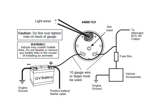
Autometer fuel gauge wiring diagram
Autometer Gauge Wiring Diagram - Cadician's Blog Autometer Fuel Gauge Wiring - Great Installation Of Wiring Diagram • - Autometer Gauge Wiring Diagram You can always depend on Wiring Diagram as an crucial reference that will enable you to preserve time and money. Using the aid of the guide, you'll be able to very easily do your personal wiring projects. Autometer Pro Comp Ultra Lite Wiring Diagram Autometer Boost Gauge Wiring Diagram. How to Install an Auto Meter Pro-Comp Ultra-Lite Air/Fuel Ratio Gauge - Electric on Your M or wiring diagram for your specific vehicle to learn which wire is the signal. WARNING. Do not connect ohm meter to oxygen sensor, or touch wire to ground or power. Damage to oxygen sensor will result. diagramweb.net ... AutoMeter gauges, Fuel Level, Painless Wiring - Hot Rod Forum I have a new fuel cell, painless wiring kit, and auto meter gauges that I am trying to wire up. I took a buddy for a ride around the neighborhood and the fuel pump started to make some weird noises, so I stopped and asked him to check and see if the fittings were leaking, because the fuel gauge read full.
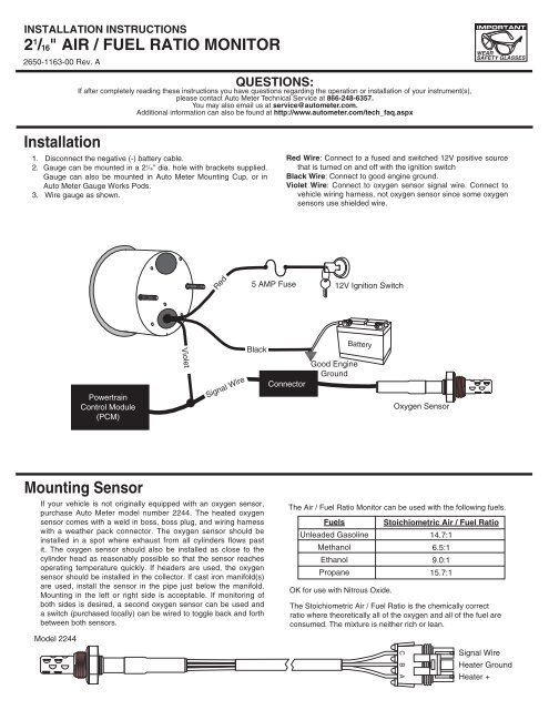
Autometer fuel gauge wiring diagram. Autometer Electric Fuel Pressure Gauge Wiring Diagram ... Mar 03, 2022 · Wiring Diagram Autometer Electric Fuel Pressure Gauge Wiring Diagram on March 3, 2022 If a new hole is drilled in the firewall a grommet is recommended. Gauge mounts in a 25 8 hole for 2 5 8 gauges and a 2 1 16 hole for 2 1 16 gauges. Pin On Velvet 1 For fuel pressure gauge install the 1 8 npt pressure sender into the fuel system see caution below. Autometer Wideband Wiring Diagram - easywiring A wiring diagram is a simplified conventional photographic representation of an electrical circuit. Components available on your auto meter wideband air fuel gauge. Gauge can also be mounted in auto meter mounting cup or in auto meter gauge works pods. How to Install an Auto Meter Pro-Comp Ultra-Lite Air/Fuel ... Gauge can be mounted in a 21⁄16" dia. hole with brackets supplied. Gauge can also be mounted in Auto Meter Mounting Cup, or in Auto Meter Gauges Works Pods. Wire gauge as shown. Red Wire: Connect to a fused and switched 12V positive source that is turned on and off with the ignition switch. Black Wire: Connect to good engine ground. PDF Fuel Level Sender Installation Instructions - vdo-gauges.com wiring instructions. Always disconnect battery ground before making any electrical connections. Parts of the Fuel Level Sender Unit to be Ad Fuel Level Sender Installation: Refer to the VDO catalog for matching fuel gauges. The unit can be adjusted to read accurately in tanks from 6" to 23" deep. Diagram B I. Measure the depth of your fuel tank.
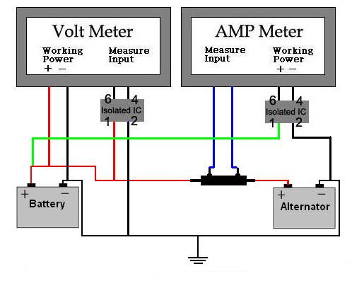
How to wire Auto Meter fuel gauge to factory harness ... This only works with the harness that had the gas gauge in the dash. On the indash tach, the wiring harness had this terminal going up to the negative side of the ignition coil. Also in the original harness should be an ignition 12 volt source to power up the gauge and also a ground. By tracing these circuits off of the old dash, you should be ... Autometer Voltmeter Wiring Diagram Perfect Modern ... As stated earlier, the traces in a Autometer Gauge Wiring Diagram signifies wires. Sometimes, the cables will cross. However, it does not mean connection between the wires. Injunction of two wires is generally indicated by black dot on the junction of 2 lines. There'll be main lines that are represented by L1, L2, L3, and so on. How to Wire Auto Meter Fuel Gauges - It Still Runs Connect the "S" wire to the fuel-sender signal wire you removed from the stock fuel gauge. This wire is fed directly to the post on the fuel-level sender in the fuel tank. Twist these two wires together and cover them with a layer of electrical tape. Use your test lamp to determine the fuse for the dashboard instrument lights. Oil Pressure Gauge Wiring Diagram - Studying Diagrams Autometer oil pressure gauge wiring diagram wiring diagram is a simplified adequate pictorial representation of an electrical circuit it shows the components of the circuit as simplified shapes and the aptitude and signal associates in the midst of the devices. Anyways the 3 wires are orange tan and grey.
March 2022 - Page 26 - Wiring Sample Autometer Electric Fuel Pressure Gauge Wiring Diagram. on March 3, 2022 March 3, 2022 Leave a Comment on Autometer Electric Fuel Pressure Gauge Wiring Diagram. If a new hole is drilled in the firewall a grommet is recommended. Gauge mounts in a 25 8 hole for 2 5 8 gauges and a 2 1 16 hole for 2 1 16 gauges. Pin On Velvet 1 For fuel pressure ... Wiring Diagram Boat Fuel Gauge - Wiring Diagram Line Wiring Diagram Boat Fuel Gauge Wiring Diagram Line Wiring Diagram. Wiring Diagram Line We are make source the schematics, wiring diagrams and technical photos ... boatus frequently asked questions moeller installation electrical for trim other add aux car charger ifish auto meter automotive replacement panel pressure analog black online saint ... Autometer Gauge Wiring Diagram - easywiring Sep 10, 2021 · Autometer gauge wiring diagram. Step 1 use the wiring diagram and test light or multi meter to locate the positive wire from the alternator to the fuse block. An initial look at a circuit layout may be complex but if you could check out a subway map you could read schematics. Autometer Gauge Wiring Diagram - Wiring Diagram Nov 19, 2020 · Autometer Fuel Gauge Wiring – Great Installation Of Wiring Diagram • – Autometer Gauge Wiring Diagram You can always depend on Wiring Diagram as an crucial reference that will enable you to preserve time and money. Using the aid of the guide, you’ll be able to very easily do your personal wiring projects.
Fuel Level Gauges Autometer How They Work How To Install ... Fuel Level Gauges Autometer How They Work How To Install Tutorial Instructions Ohms Wiringhttp:// -----...
Autometer Trans Temp Gauge Wiring Diagram Trans Temp Gauge Installation: but an A-pillar gauge mount is available as a professional location to mount two gauges. diagramweb.net has a 2 & 3 gauge pod available Pictured below is a copy of the wiring diagram for the Autometer Transmission Temperature Gauge. STEP 4.
Autometer Fuel Level Gauge Wiring Diagram - autocardesign Jan 19, 2020 · Autometer Fuel Level Gauge Wiring Diagram – wiring diagram is a simplified all right pictorial representation of an electrical circuit. It shows the components of the circuit as simplified shapes, and the capability and signal friends between the devices.
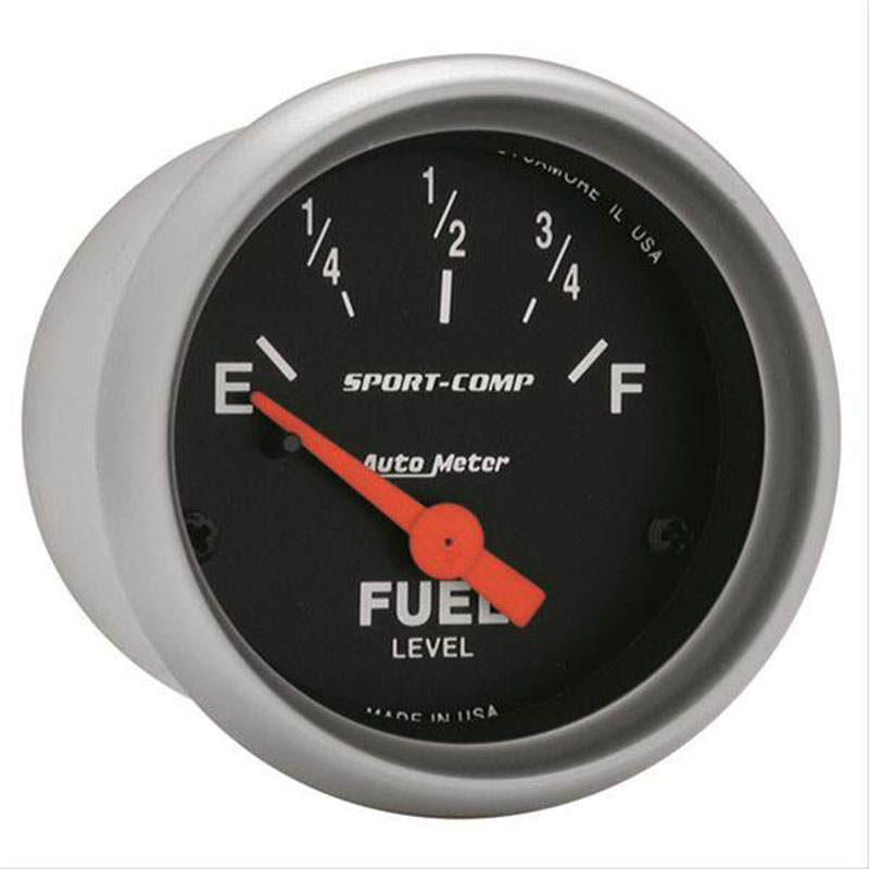
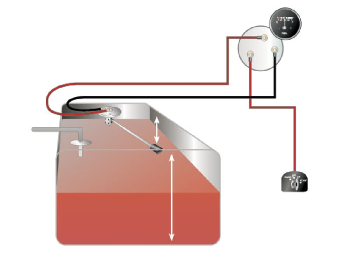
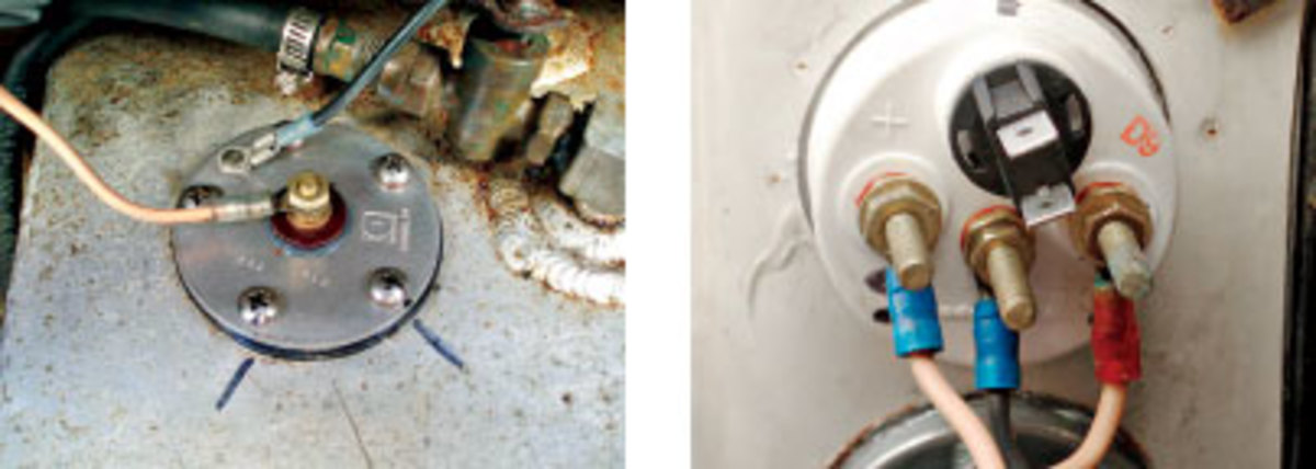
PDF Auto Meter Gauges Installation Instructions gAUge (back view) Fuel Level 1. Disconnect negative (-) battery cable. 2. Gauge connects to fuel sender on fuel tank. Existing wires may be used, or route proper length of 18 gauge, 2 conductor wire from fuel tank to gauge. Connect one end to terminal post on fuel level sender and the opposite end to the sender (S) terminal spade on back of gauge.
Fuel Gauge Wiring Diagram - Wiring diagram online Mar 18, 2022 · Wiring Diagram Diagrams Darren Criss Gauge Together With Sunpro Gauges Wiring Diagram Also Vdo Gauge Wiring Diagram Additionally On A 12 Volt Gauge Wiring Diagram For Vw Together With Wiring Diagram For Auto Meter Gauge. Next, connect a wire from the float on the fuel tank to the negative terminal of the fuel gauge.
Autometer Oil Pressure Gauge Wiring Diagram Pictured below is a copy of the wiring diagram for the Autometer Oil Pressure Gauge. To install an oil pressure gauge you will first need to purchase one. Pictured below is a copy of the wiring diagram for the Autometer Oil Pressure Gauge. left is labeled 'S', signal wire from oil pressure or water temp sensor? .
Autometer Gauge Wiring Diagram | Wirings Diagram Nov 30, 2020 · As stated earlier, the traces in a Autometer Gauge Wiring Diagram signifies wires. Occasionally, the wires will cross. However, it doesn’t imply connection between the cables. Injunction of two wires is usually indicated by black dot on the intersection of 2 lines.
1969 Camaro Fuel Gauge Wiring Diagram - The Wiring 1969 camaro fuel gauge wiring diagram. 1969 Chevy Fuel Gauge Wiring images photos collection in which released below ended up being properly picked and also published by admin just after choosing the.This circuit board is different for a warning light versus a factory console gauge car. The 1969 low fuel module operates by sending a ground signal on the yellow wire to a bulb located in the ...
PDF Auto Meter Gauges Installation Instructions - CARiD.com Fuel Level. 1. Gauge connects to fuel sender on fuel tank. Existing wires may be used, or route proper length of 18 gage, wire from fuel tank to gauge. If a new hole is drilled in the firewall a grommet is recommended. Connect one end to terminal post on fuel level sender and the opposite end to the sender (S) terminal spade on back of gauge. 2.
PDF Installation Instructions Short Sweep Electric Gauges 18 gage, wire from fuel tank to gauge. If a new hole is drilled in the firewall a grommet is recommended. Connect one end to terminal post on fuel level sender and the opposite end to the sender (S) terminal spade on back of gauge. 2. Connect ground wire from ground post on gauge to suitable chassis ground. 3.
wiring up autometer fuel level gauge - Four Eyed Forums I just got done installing a new fuel level sending unit in my 86 gt mustang and purchased a new autometer fuel gauge to go with it. But as far as wiring is concerned, I don't have a clue. Someone had mentioned that I could t-tap a wire off of the stereo power wire (which I did). But I can't seem to get the damn thing to work.
AutoMeter gauges, Fuel Level, Painless Wiring - Hot Rod Forum I have a new fuel cell, painless wiring kit, and auto meter gauges that I am trying to wire up. I took a buddy for a ride around the neighborhood and the fuel pump started to make some weird noises, so I stopped and asked him to check and see if the fittings were leaking, because the fuel gauge read full.
Autometer Pro Comp Ultra Lite Wiring Diagram Autometer Boost Gauge Wiring Diagram. How to Install an Auto Meter Pro-Comp Ultra-Lite Air/Fuel Ratio Gauge - Electric on Your M or wiring diagram for your specific vehicle to learn which wire is the signal. WARNING. Do not connect ohm meter to oxygen sensor, or touch wire to ground or power. Damage to oxygen sensor will result. diagramweb.net ...
Autometer Gauge Wiring Diagram - Cadician's Blog Autometer Fuel Gauge Wiring - Great Installation Of Wiring Diagram • - Autometer Gauge Wiring Diagram You can always depend on Wiring Diagram as an crucial reference that will enable you to preserve time and money. Using the aid of the guide, you'll be able to very easily do your personal wiring projects.












0 Response to "41 autometer fuel gauge wiring diagram"
Post a Comment