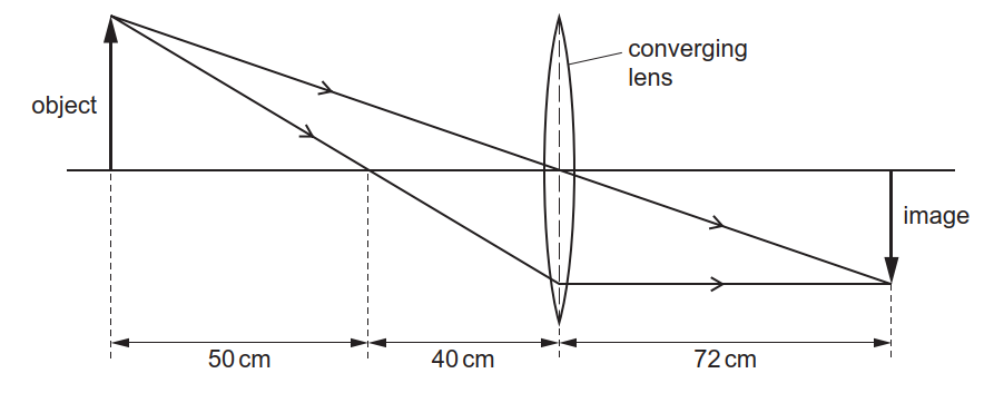
43 based on the ray diagram and distances shown in figure 1
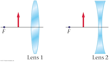
Section Bank C/P Question 11 | Student Doctor Network 9. Reaction score. 8. Mar 15, 2016. #1. The question asks for the focal length of the lens. All parallel lines going through converging lens should pass through focal point, and light from a single source going through converging lens should exit in parallel rays...but the figure shows neither. I went with focal length =4cm as my choice but ... PDF RAY OPTICS I - physics.pomona.edu dially away from the point as shown in Figure 6.1. When we look at such an object, our eyes col-lect some of the scattered photons and our brains construct a mental image of the object based on the number, color, and trajectory of the photons collected. rock sunlight point eye Figure 6.1: An illustration of how we can represent
NCERT Exemplar Class 8 Science Chapter 16 Light - Learn CBSE (b) Positions of the mirrors are as shown in the figure. (c) Mirrors should be placed at an angle of 45° with respect to the incident light. So, that the rays can move forward. (d) Direction of rays is shown in the figure Or In place of Fig. (i) and Fig. (ii) we may also use this combine figure for answer of Q 20. (b) and (d).

Based on the ray diagram and distances shown in figure 1
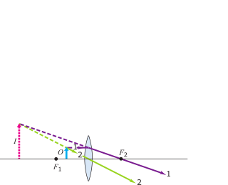
PDF Physics 41 Chapter 37 Sample Problems - Santa Rosa Junior ... 24.1 1.65 m 0.13 m From ray L a b 2 ... When the light illustrated in the diagram passes through the glass block, it is shifted laterally by the distance . d. Taking : n ... The light beam shown in the figure makes an angle of 20.0° with the normal line . NN ' in the linseed oil. Determine MCQ Questions for Class 10 Science Chapter 10 Light ... Check the below NCERT MCQ Questions for Class 10 Science Chapter 10 Light Reflection and Refraction with Answers Pdf free download. MCQ Questions for Class 10 Science with Answers were prepared based on the latest exam pattern. We have Provided Light Reflection and Refraction Class 10 Science MCQs Questions with Answers to help students understand the concept very well. Solved Figure 1 shows the principal-ray diagram of the ... Figure 1 shows the principal-ray diagram of the image formation by a converging lens with focal length f and object distance s = 2f/3 to the left of the lens. a. Use the equation m = y'/y = -s'/s to find the image distance s' in terms of f. b. Based on your result, is the image real or virtual? Is it to the left or right of the
Based on the ray diagram and distances shown in figure 1. Solved (Figure 1) shows the principal-ray diagram of the ... Transcribed image text: (Figure 1) shows the principal-ray diagram of the image formation by a converging lens with focal length f and object distance S = 2f/3 to the left of the lens. F1 Part A Use the equation m = y'/y = -8' /8 to find the image distance s' in terms of f. Express your answer in terms of f. Images Formed by Plane Mirrors - University Physics Volume 3 Images 1 and 2 result from rays that reflect from only a single mirror, but image 1,2 is formed by rays that reflect from both mirrors. This is shown in the ray-tracing diagram in part (b) of . To find image 1,2, you have to look behind the corner of the two mirrors. Ray Diagrams - Physics Classroom Step-by-Step Method for Drawing Ray Diagrams. The method of drawing ray diagrams for double convex lens is described below. The description is applied to the task of drawing a ray diagram for an object located beyond the 2F point of a double convex lens. 1. Pick a point on the top of the object and draw three incident rays traveling towards the ... Geometrical Optics: Focal Length of a Concave Mirror and a ... Look at the ray diagram shown in the figure. The distances are measured from the pole P. The incident ray (from the object to the mirror) is from the left to the right. Thus, u, v and f are all negative (by sign convention). SVG-Viewer needed. The u versus v graph is shown in the figure. The important points in this figure are:
16.1 Reflection - Physics | OpenStax Have students construct a ray diagram for an object reflected in a plane mirror. Point out to them that all information can be represented in the diagram by using just paper, a pencil, a ruler, and a protractor. Students may use the preceding video and Figure 16.5 to help them to draw the necessary rays for the diagram. Have them compare the ... PDF Geometrical Optics 11 Position the lenses di erent distances and in di erent order from the light source and observe the various ray diagrams that are produced. An example is shown in Figure 10. Try others. Figure 10 c 2013-2014 Advanced Instructional Systems, Inc. and Texas A&M University. Portions from North Carolina State University. 7 16.3 Lenses - Physics - OpenStax An expanded view of the path taken by ray 1 shows the perpendiculars and the angles of incidence and refraction at both surfaces. The power, P, of a lens is very easy to calculate. It is simply the reciprocal of the focal length, expressed in meters P = 1 f. 16.15 The units of power are diopters, D, which are expressed in reciprocal meters. PDF MasteringPhysics: Assignment Print View ... Hint B.1 Relationship between and Hint not displayed Express your answer in degrees in terms of . Notice that the degrees symbol is already listed for you, so just use the number "23" to indicate 23 degrees. ANSWER: = Correct Part C Now, find the angle shown in the figure in terms of and . Hint C.1 Angles in a triangle
PDF Untitled Document [ ] middle section of Figure O4.1 shows the ray diagram for this image. Mathematically, the location and magnification are found using: 1 90 1 1 30 45 cm S cm + S cm ¢ = Þ ¢ = and M ( cm ) 1 cm 45 = - 90 = -0.5. In summary, based on the sign conventions, the positive value for S' indicates that A Practical Introduction to Light Field Microscopy Figure 1.1: A light field microscope is created by inserting a microlens array (D) of focal length at the intermediate image plane of an optical microscope consisting of an objective (B) with focal length and tube lens (T) with focal length .The sensor (E) is now placed at the back focal plane of the microlens array. The different ray bundle diagrams correspond to paraxial rays from points in ... ICSE Solutions for Class 10 Physics - A Plus Topper Figure Based Short Answers. Question 1: ... The ray diagram is shown in figure. For the object AB, the images is A'B'. ... This is shown in figure. The distance of second focal point F 2 from the optical centre O of the lens (i.e., OF 2) is called the second focal length f 2. Two mirrors are inclined at an angle theta as shown in the ... Let M N and A B parallel to M N is incident on M P and the ray after third reflection on M P at B retraces its path as shown in the diagram. Hence C D is perpendicular to M P. This means ∠ B C N = ∠ D C M = 9 0 ∘ − θ. A B ∣ ∣ M N and B C is the intercept. So ∠ P B A = corresponding ∠ P B N = θ. And ∠ A B C = 1 8 0 ∘ − 2 ...
PDF] The Impact of an Interactive Ray Diagram Teaching Module ...
To Find Image Distance For Varying Distance Of A ... - BYJUS The images obtained from these lenses can be either a real image or a virtual image. Below is an experiment to find the image distance for varying object distances of a convex lens with ray diagrams. Aim Theory Materials Required Experimental setup Procedure Ray Diagrams Observation Table Calculations Result Precautions Viva Questions. Aim

AAMC B/C section bank #11 : r/Mcat
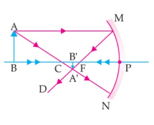
Concave Mirrors And Convex Mirrors - Image Formation, Ray ... Concave Mirror Ray Diagram lets us understand that, when an object is placed at infinity, a real image is formed at the focus. The size of the image is much smaller compared to that of the object. When an object is placed behind the center of curvature, a real image is formed between the center of curvature and focus.
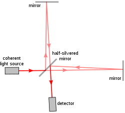
Interferometry - Wikipedia
Physics Tutorial: Ray Diagrams for Plane Mirrors The four steps of the process for drawing a ray diagram are listed, described and illustrated below. 1. Draw the image of the object. Use the principle that the object distance is equal to the image distance to determine the exact location of the object. Pick one extreme on the object and carefully measure the distance from this extreme point ...

Test: AAMC Material - missed chemistry questions | Quizlet
SOLVED:Figure 34.37 \mathrm{e} shows the principal-ray ... That's the distance of the image divided by the distance of the object, so using in order to find a stash in terms of f using 10 lens formula, which is a relation Among the object distance is the image distance s dash and the focal length f and it says one by s dash plus one by S is equal to one by f Let it be question number one multiplying ...
Ray (optics) - Wikipedia
Important Question for Class 10 Science Light Reflection ... 24. What is the minimum number of rays required for locating the image formed by a concave mirror for an object. Draw a ray diagram to show the formation of a virtual image by a concave mirror. [Delhi] Answer. 25. The refractive index of water is 1.33 and the speed of light in air is 3 x 10⁸ ms-1.
Cased Based MCQ - Following figure illustrates the ray ...
[Latest] Light Reflection And Refraction MCQ Assertion Cl.10 MCQ 1-25. 1. Study the given ray diagrams and select the correct statement from the following (a) Device X is a concave mirror and device Y is a convex lens, whose focal lengths are 20 cm and 25 cm respectively. (b) Device X is a convex lens and device Y is a concave mirror, whose focal lengths are 10 cm and 25 cm respectively.
focal point | optics | Britannica
PDF 23-1 The Ray Model of Light - Boston University EXPLORATION 23.2 - Using a ray diagram to find the location of an image Figure 23.9: An arrow located some distance in front of a plane mirror. Step 1 - An arrow is placed in front of a vertical plane mirror, as shown in Figure 23.9. Sketch two rays of light, which travel in different

Section bank cp 11 : r/Mcat
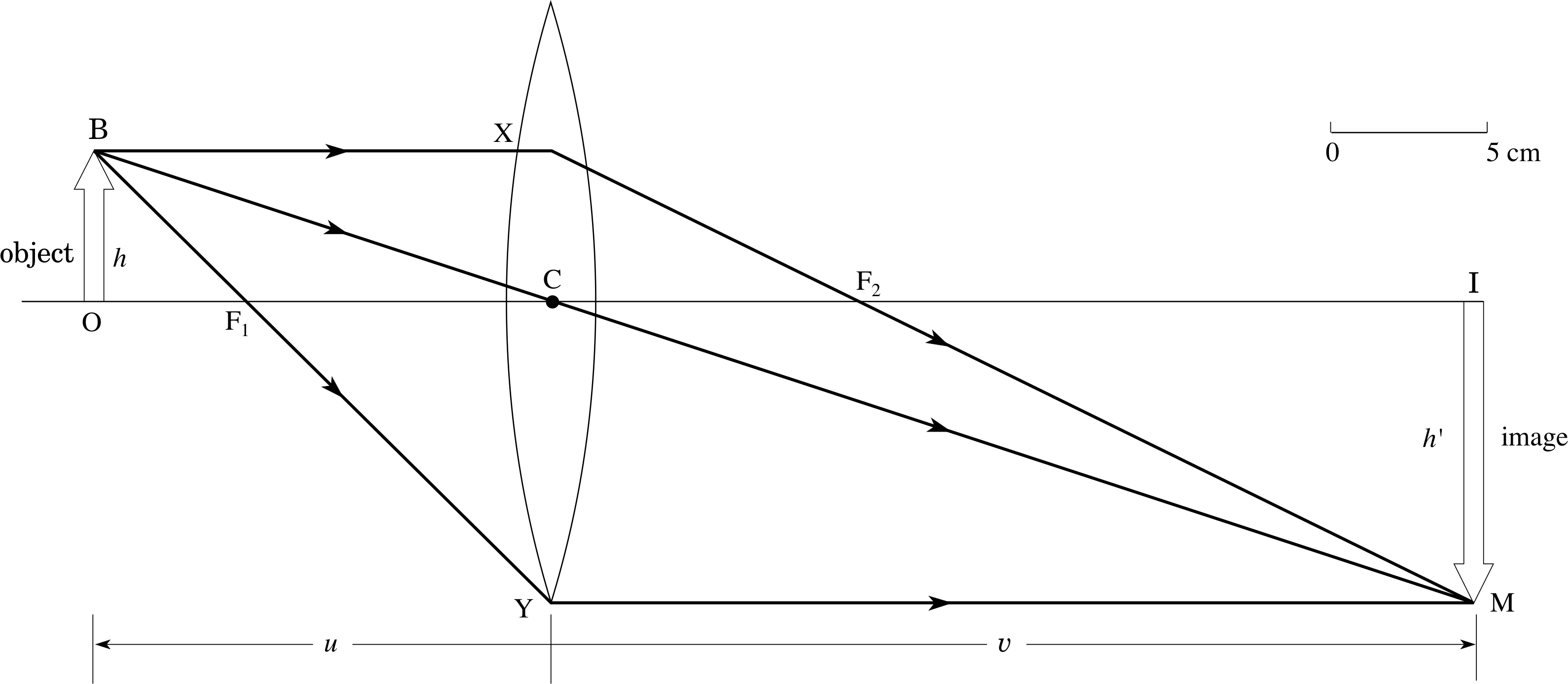
Thin Lenses - University Physics Volume 3 A ray entering a diverging lens parallel to the optical axis exits along the line that passes through the focal point on the same side of the lens (ray 1 in part (b) of the figure). A ray passing through the center of either a converging or a diverging lens is not deviated (ray 2 in parts (a) and (b)).

16.3 Lenses | Texas Gateway
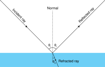
PDF Cambridge IGCSE Physics (0625) Past paper questions and ... 10 v1 4Y11 Cambridge IGCSE Physics - past paper questions and answers Light - answers . Core 1 (a) refraction (b) (i) the normal should be drawn at right angles to the surface of the water at S (ii) the angle of incidence should be shown between the normal and the incident ray (c) (i) the beam should be reflected away from the normal along ST (ii) 1 total internal reflection
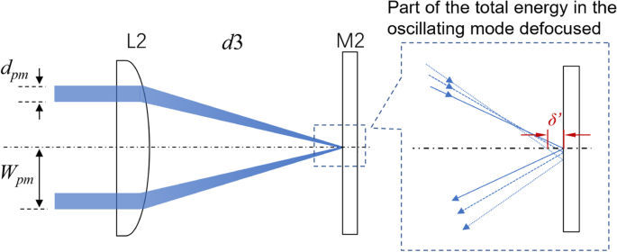
Intracavity spherical aberration for selective generation of ...
(a) A point object 'O' is kept in a medium of ... - Toppr Ask (a) A point object 'O' is kept in a medium of refractive index n in front of a convex spherical surface of radius of curvature R which separate the second medium of refractive index n 2 from the first one as shown in the figure. Draw the ray diagram showing the image formation and deduce the relationship between the object distance and the image distance in terms of n 1 , n 2 and R.

q38-draw-a-ray-diagram-to-show | LIDO
Figure 3. Ray diagram for image formation of an extended ... A brief outline of the interactive ray diagram teaching module is shown in Figure 4. The learners thus used the three ray-diagram tasks to determine the relationships between: 1. object size and ...

Biocompatible surface functionalization architecture for a ...
Solved Figure 1 shows the principal-ray diagram of the ... Figure 1 shows the principal-ray diagram of the image formation by a converging lens with focal length f and object distance s = 2f/3 to the left of the lens. a. Use the equation m = y'/y = -s'/s to find the image distance s' in terms of f. b. Based on your result, is the image real or virtual? Is it to the left or right of the

Using 3D Laser Scanning Technology to Create Digital Models ...
MCQ Questions for Class 10 Science Chapter 10 Light ... Check the below NCERT MCQ Questions for Class 10 Science Chapter 10 Light Reflection and Refraction with Answers Pdf free download. MCQ Questions for Class 10 Science with Answers were prepared based on the latest exam pattern. We have Provided Light Reflection and Refraction Class 10 Science MCQs Questions with Answers to help students understand the concept very well.

Geometrical ray diagram showing lateral displacement effect ...
PDF Physics 41 Chapter 37 Sample Problems - Santa Rosa Junior ... 24.1 1.65 m 0.13 m From ray L a b 2 ... When the light illustrated in the diagram passes through the glass block, it is shifted laterally by the distance . d. Taking : n ... The light beam shown in the figure makes an angle of 20.0° with the normal line . NN ' in the linseed oil. Determine
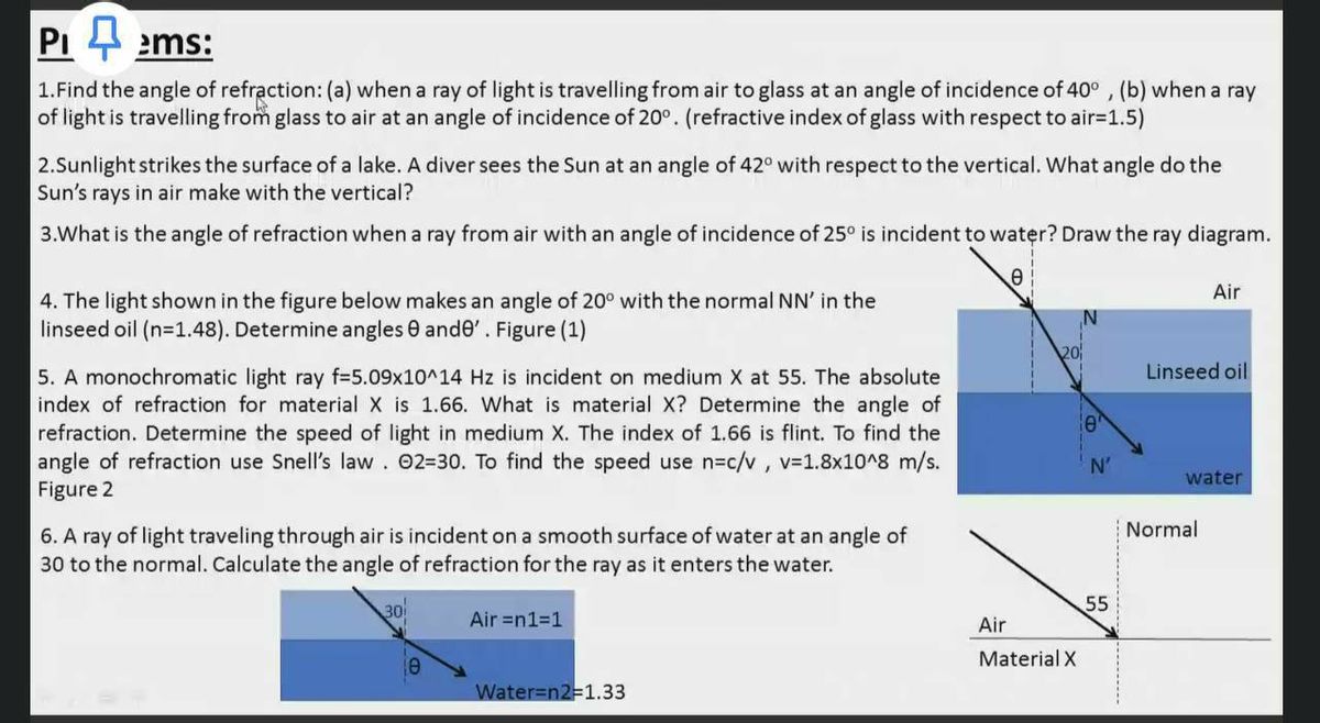
Answered: 1.Find the angle of refraction: (a)… | bartleby

ఈనాడు ప్రతిభ : Job Notifications | Tests | Study ...
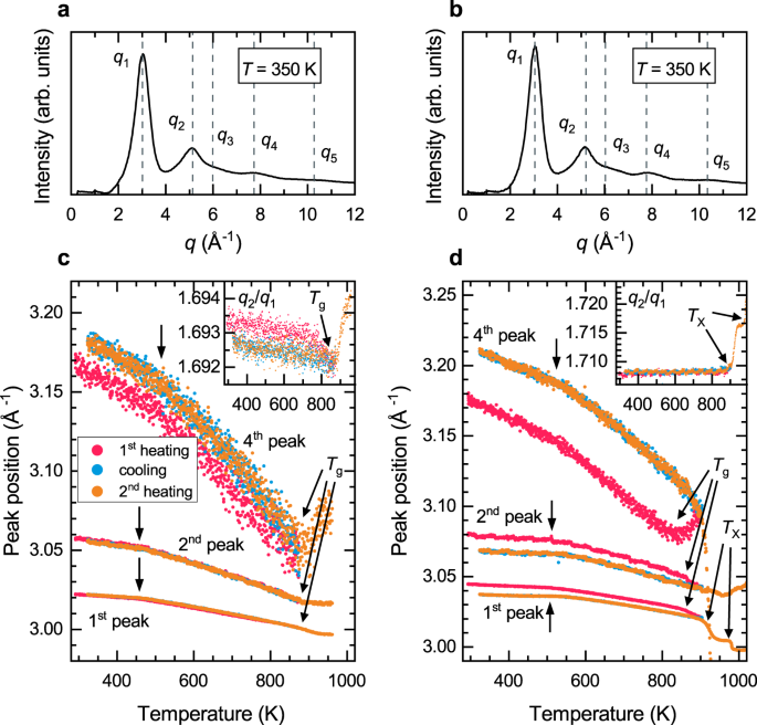
Atomic structure evolution related to the Invar effect in Fe ...
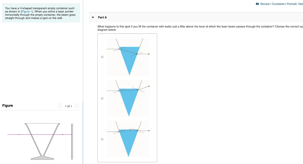
Solved A Review Constants Periodic Tab You have a V-shaped ...
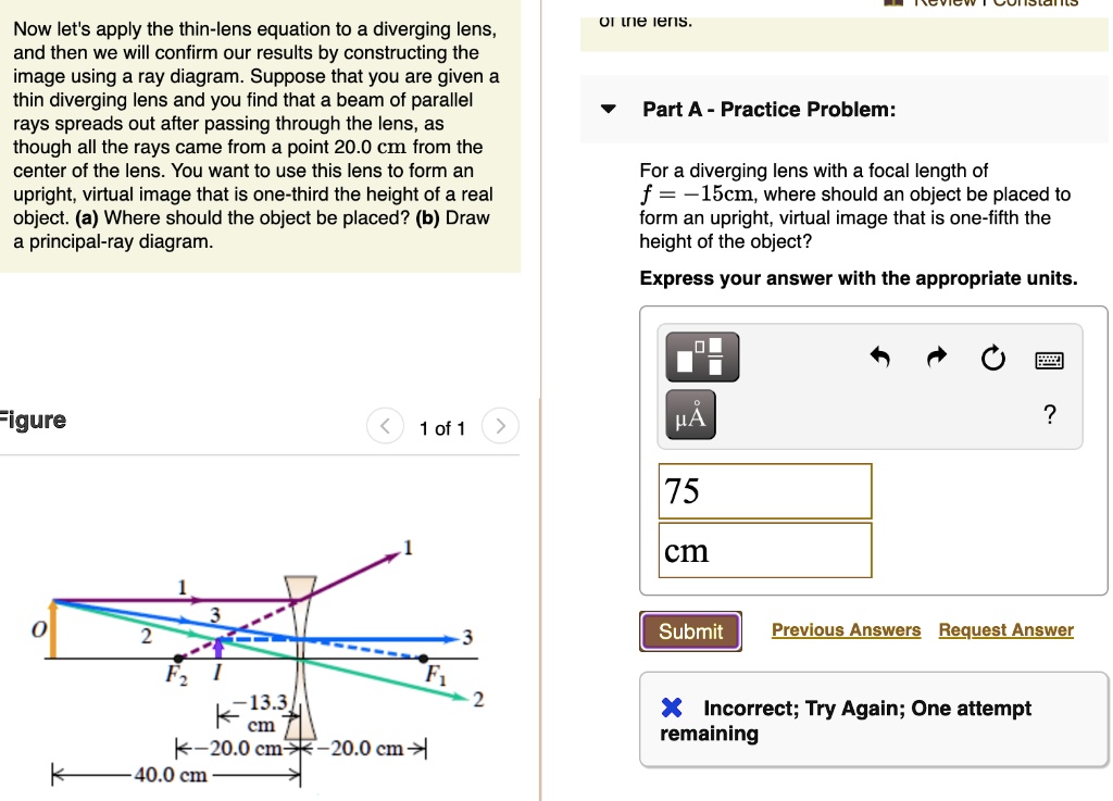
SOLVED:Now let's apply the thin-lens equation to a diverging ...
PPLATO | FLAP | PHYS 6.3: Optical elements: prisms, lenses ...

Mr Toogood Physics - Lenses
Mirrors and lenses

Performance of Steel-Reinforced Concrete Beam-to-Column ...

The Earth beneath the sea : History . Fig. 1. Ray diagram and ...
![SPOILER] AAMC Section Bank C/P #11 : r/Mcat](https://preview.redd.it/4pnf2v7yrcg21.png?width=1147&format=png&auto=webp&s=35833190a4eab9ade1422b9e3cd074f1f6aaee33)
SPOILER] AAMC Section Bank C/P #11 : r/Mcat
Changing the way you learn | Quiz

Ray tracing 3D spectral scenes through human optics models ...
Quantitative phase retrieval with low photon counts using an ...
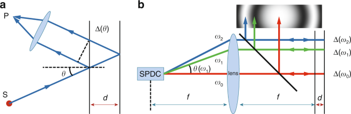
Angular-spectrum-dependent interference | Light: Science ...
P6 LENSES
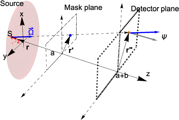
Coded masks for imaging of neutrino events | SpringerLink
Physics Tutorial: Ray Diagrams - Concave Mirrors

Ray Diagrams (1 of 4) Concave Mirror - YouTube

Draw a ray diagram for the following situation (an object far ...
18-1 RAY OPTICS
arXiv:1702.03240v1 [quant-ph] 10 Feb 2017

Graphical Optimization Method for Symmetrical Bidirectional ...
Lecture 21
Substrate aberration and correction for meta-lens imaging: an ...
![SPOILER] AAMC Section Bank C/P #11 : r/Mcat](https://preview.redd.it/il1aujqzrcg21.png?width=1077&format=png&auto=webp&s=a14f8a8963116a10c3735d3e37e69c3700547d15)
SPOILER] AAMC Section Bank C/P #11 : r/Mcat
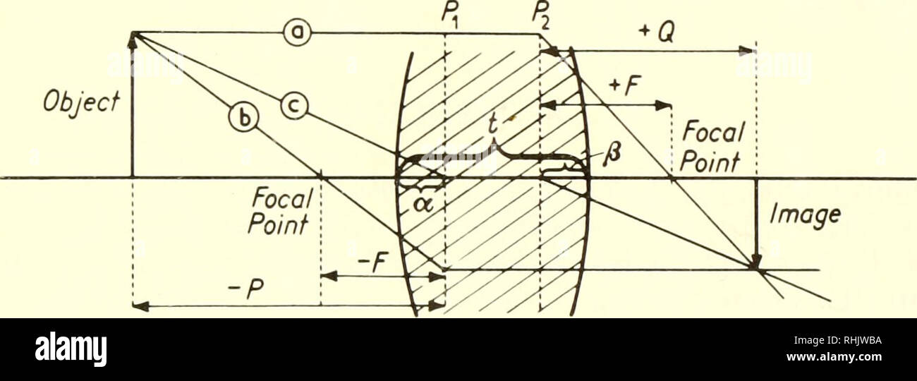
Biophysical science. Biophysics. Appendix B 603 All of the ...
Solved Figure 1 shows the principal-ray diagram of the image ...

Stochastic Versus Ray Tracing Wireless Channel Modeling for ...
0 Response to "43 based on the ray diagram and distances shown in figure 1"
Post a Comment