42 spectrum analyzer block diagram
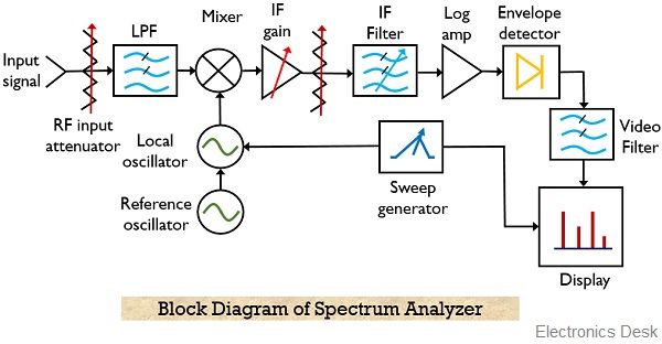
Digital Fourier Analyzer | Block Diagram of Digital Signal ... A digital signal analyzer block diagram is shown in Fig. 9.15. This digital signal analyzer employs an Fast Fourier Transform algorithm. The block diagram is divided into three sections, namely. the input section, the control section and. the display section. The input section consists of two identical channels. Spectrum Analyzer - Electronics Club Spectrum Analyzer Block Diagram of Spectrum Analyzer. The above Figure shows a simplified block diagram of a spectrum analyzer. Normally, for RF or microwave signal analysis, the swept technique is preferred. The main function of the spectrum analyzer is to obtain the amplitude versus frequency plot from the frequency spectrum under the test.
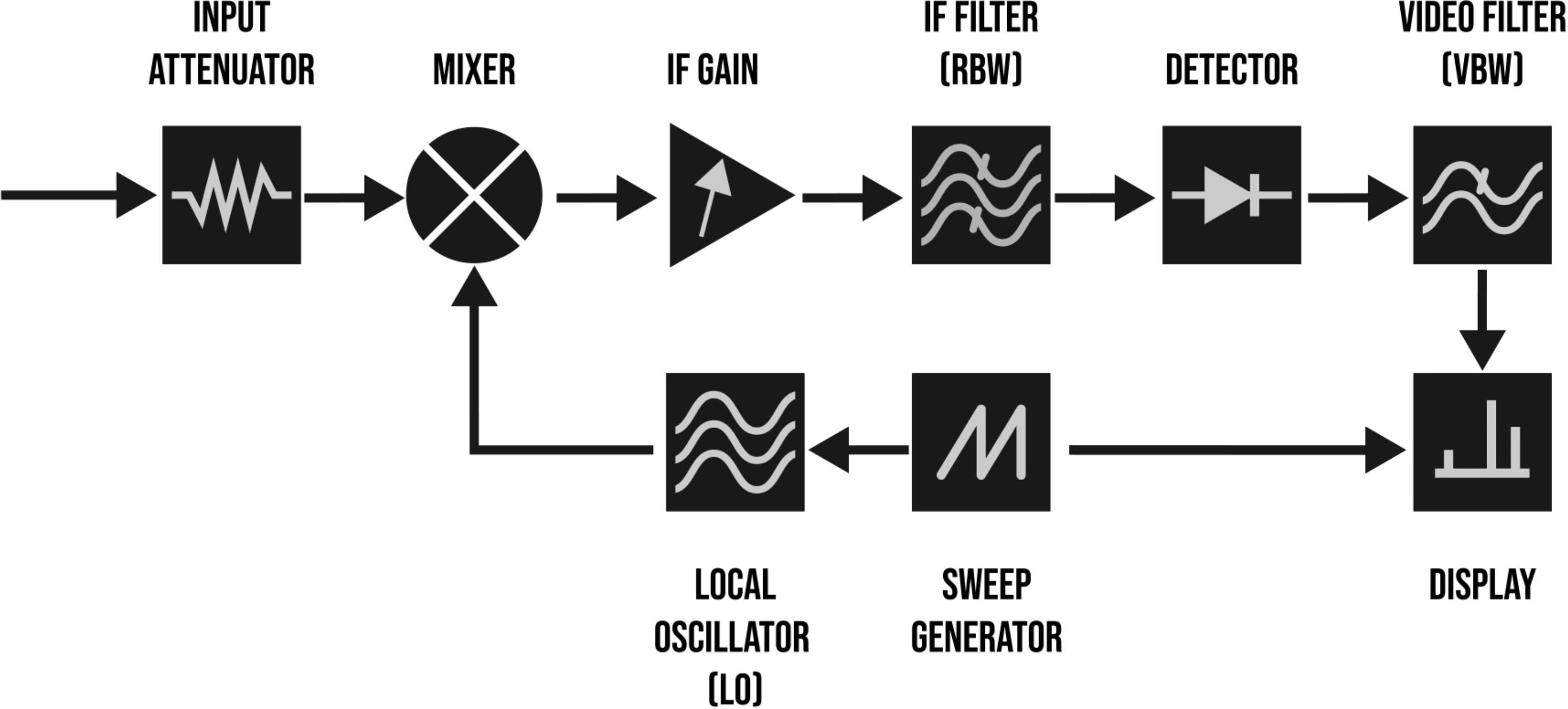
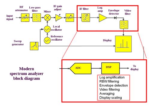
What is Spectrum Analyzer? Block Diagram, Working and ... The figure below shows the block diagram representation of a spectrum analyzer with digital display: As we can see the spectrum analyzer is composed of components like RF attenuator, mixer, IF filter, detector, sweep generator, local oscillator and display unit. So, let us now understand the operation performed by each block individually.

Spectrum analyzer block diagram
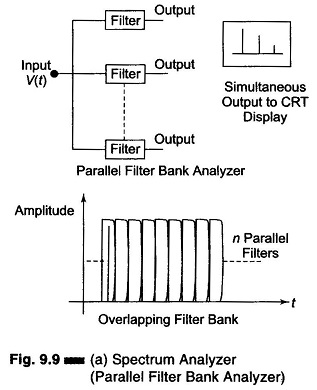
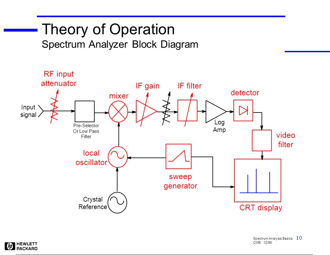
PDF SPECTRUM ANALYZER - Bharath Institute of Higher Education ... A block diagram of an audio spectrum analyzer. SPECTRUM ANALYZERS •The real-time, or multichannel. analyzer is basically a set of stagger-tuned bandpass filters connected through an electronic scan switch to a CRT. The composite amplitude of the signal within each filters bandwidth is displayed as a ... PDF Tim Huang 2022.02 SWEPT SPECTRUM ANALYZER BLOCK DIAGRAM Pre-Selector or Low Pass Input Filter Crystal Reference Oscillator Log Amp RF Input Attenuator Mixer IF Filter (RBW) Envelope Detector Video Filter Local Oscillator Sweep Generator IF Gain Input signal Display APEX Technologies High resolution Optical Spectrum Analyzers. Discover the world best resolution Optical Spectrum Analyzer model with 5 MHz/40 fm optical bandwidth filter resolution. Tunable laser, DFB, power meter, variable attenuator, tunable filter, EDFA, switch
Spectrum analyzer block diagram. PDF Experiment 1 Spectrum Analyzer - HIT Figure 3 Simpli-ed block diagram of Heterodyne spectrum analyzer 1.7 Input Section The input to the spectrum analyzer block diagram has a step attenuator, followed by an ampli-er. The purpose of this input section is to control the signal level applied to the rest of the instrument. time A m p l i t u d e ( v ) Simplified Spectrum Analyzer Block Diagram | Signal Hound Simplified Spectrum Analyzer Block Diagram. Posted February 25, 2016. ← Return to Introduction To Practical Spectrum Analysis. 5 RF Transmitter Measurements Every Engineer Should Know - … 17.02.2022 · The block diagram of a generic RF transmitter shows baseband information conditioned with signal processing, ... such as a spectrum analyzer with phase noise much better than the device under test (DUT), is connected directly to the DUT, and the phase noise is plotted with a test program or internal personality. For higher performance phase noise … Infrared - Wikipedia Definition and relationship to the electromagnetic spectrum. There is no universally accepted definition of the range of infrared radiation. Typically, it is taken to extend from the nominal red edge of the visible spectrum at 700 nanometers (nm) to 1 millimeter (mm). This range of wavelengths corresponds to a frequency range of approximately 430 THz down to 300 GHz.
Integrated Synthesizer and VCO Data Sheet ADF4360-7 functional block diagram muxout cp v vco ref in clk data le av dd dv dd r set agnd dgnd cpgnd ce v tune c c c n l1 l2 rf out a rf out b vco core phase comparator mute divsel = 2 divsel = 1 n = (bp + a) load load charge pump output stage multiplexer integer register 13-bit b counter 14-bit r counter 24-bit function latch 24-bit data register 5-bit a counter prescaler p/p+1 multiplexer lock ... Spectrum Analyzers - Tutorialspoint The following figure shows the block diagram of filter bank spectrum analyzer. The working of filter bank spectrum analyzer is mentioned below. It has a set of band pass filters and each one is designed for allowing a specific band of frequencies. The output of each band pass filter is given to a corresponding detector. Spectrum Analyzer Block Diagram | Applications - EEEGUIDE.COM A Spectrum Analyzer Block Diagram provides a calibrated graphical display on its CRT, with frequency on the horizontal axis and amplitude (voltage) on the vertical axis. Displayed as vertical lines against these coordinates are sinusoidal components of which the input signal is composed. PDF Spectrum Analyzers Field User Guide Block Diagram Description (continued) The detectorsamples the IF signal and converts it to digital samples. The input to the detector normally is many more samples than can be displayed on the screen. attenuation, RBW, and VBW The detector groups samples, creating one group for each display point.
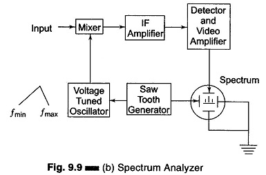
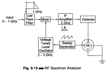
PDF Spectrum Analyzer Basics - Kansas State University Using the HP4195A Spectrum Analyzer Setting the Mode and Connecting the Input { In the MEASUREbutton group, hit the CONFIGbutton { Choose SPECTRUMfrom the softkeys next to the screen { Connect your input signal to the R1connector in the CHANNEL 1group Setting the Frequency Sweep { In the SWEEPgroup, hit START, and then enter a start frequency. Spectrum Analyzer with Block Diagram - Electronics and ... The block diagram of a spectrum analyzer of swept frequency type is shown in Figure. It can be seen from the block diagram that the horizontal deflection is obtained from a saw tooth wave generator. The output of the saw tooth wave controls the frequency of the Voltage Controlled Oscillator (also called the voltage tuned oscillator). Agilent Technologies - Spectrum Analyzer ... - Keysight The spectrum analyzer, like an oscilloscope, is a basic tool used for observing signals. Where the oscilloscope provides a window into the time domain, the spectrum analyzer provides a window into the frequency domain, as depicted in Figure 1. Figure 2 depicts a simplified block diagram of a swept-tuned superheterodyne spectrum analyzer. Digital Communication System Block Diagram with ... 22.09.2021 · Figure: Block diagram of a Digital Communication System. The figure shows a block schematic of the essential parts of a digital communication system. The block diagram explanation is: INFORMATION SOURCE. The message signal to be sent is produced by the information source. In the case of a digital source, the information source generates a ...
Block diagram of the correlation spectrum analyzer ...
Spectrum Analyzer 0...1750MHz - uni-lj.si Fig.1 - Spectrum-analyzer block diagram. As already mentioned in [1] and [2], the described spectrum analyzer is a triple-conversion receiver with the corresponding IFs around 2.1GHz, 70MHz and 10MHz. Since both the first LO and the second LO are VCOs, the first IF may be made variable.
Spectrum Analyzer Fundamentals
Spectrum Analyzer block Diagram, Basics and Working in ... In this video, i have explained Spectrum Analyzer block Diagram, Basics and Working with following outlines.1. Spectrum Analyzer basics2. Spectrum Analyzer B...

PC based (FFT) Spectrum Analyzer Block Diagram Gain ...
spectrum analyzer block diagram - Bald Engineer spectrum analyzer block diagram. By James Lewis 2019-10-16 1 Min Read. Author. James Lewis. Fan of making things beep, blink and fly. Created AddOhms. Stream on Twitch. Video Host on element14 Presents and writing for Hackster.IO. Call sign KN6FGY.

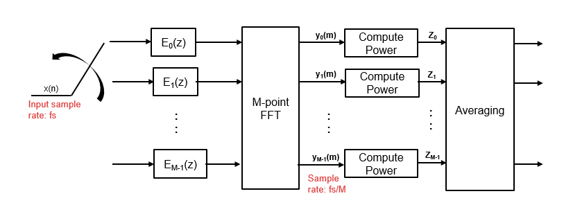
FFT Spectrum Analyzer: Fast Fourier Transform » Electronics Notes
Spectrum Analyzer - lost-contact.mit.edu The Spectrum Analyzer block accepts input signals with discrete sample times and displays frequency spectra of these signals. To use a Spectrum Analyzer block, instead of a regular scope, in a Simscape model: Add a Spectrum Analyzer block to your block diagram. If your model uses a variable-step solver, ...

Why Spectrum Analysis is Important - ppt download
Spectrum Analyzer - MathWorks The Spectrum Analyzer block accepts input signals with discrete sample times and displays frequency spectra of these signals. To use a Spectrum Analyzer block, instead of a regular scope, in a Simscape model: Add a Spectrum Analyzer block to your block diagram.

Introduction to Real-Time Spectrum Analysis. - ppt download
Spectrum Analysis Basics - Part 2: What's in a spectrum ... Below, I'll go through the blocks of this diagram to explain their function. Figure 2: A diagram of an RF attenuator, the first block of a spectrum analyzer. An RF attenuator, shown in Figure 2, ensures the signal enters the mixer at an optimum level. If a signal is too high in amplitude, it may overload the mixer, leading to distortion.
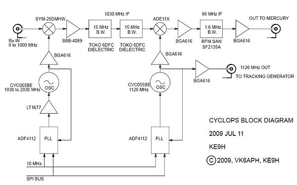
CYCLOPS - HPSDRwiki
spectrum analyzers ppt - SlideShare Spectrum Analyzer Block Diagram 15. Major blocks in a spectrum analyzer are:- 1] RF input attenuator, 2] Mixer, 3] IF (Intermediate Frequency) gain, 4] IF filter, 5] Detector, 6] Video filter, 7] Local oscillator, 8] Sweep generator, and 9] CRT display. 16. IF Filter The IF filter is a bandpass filter which is used as the window for detecting ...
Spectrum Analyzer Basics | Workbench Wednesdays - Bald Engineer
PDF Spectrum Analysis Back to Basics - Institute of Electrical ... seems confusing now - as we discuss the block diagram, the concept will become clearer. We will first go into more detail as to how the swept spectrum analyzer works. Then we will compare that architecture to the architecture of a modern FFT analyzer.

How Not to Blow Up Your Spectrum Analyzer - In Compliance ...
Spectrum Analyzer : Basics, Working, Block Diagram ... Spectrum Analyzer Block Diagram The crucial component used in the construction of the analyzer is a swept-tuned receiver. The device consists of a mixer, detector, RF type attenuator, local oscillator a LED display section. Now, let us know the operation of each component. RF Type Attenuator

Simplified spectrum analyzer block diagram. | Download ...
Spectrum Analyzer - Techplayon Spectrum analyzers are widely used within the electronics industry for analyzing the frequency spectrum of radio frequency, RF and audio signals. Block Diagram of a Spectrum Analyzer. The block diagram of a Spectrum Analyzer is shown below. Inside the analyzer, there is a mixer which converts the input signal from one frequency to another.
SPECTRUM ANALYZER
EEC2: Block Diagram: Spectrum Analyzer - YouTube This video describes the architecture and functionality of the Spectrum Analyzer.
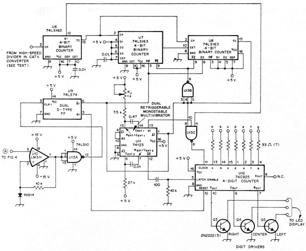
An inexpensive spectrum analyzer for the radio amateur
Detection and Measurement of Radar Signals: A Tutorial Block diagram schematic for measuring radiated waveform. 10 Example Measurement Data Figure 4. Diagram of RSEC parameters for a weather radar pulse. 11 Figure 5. Diagram of RSEC parameters for a short-range search radar pulse. 12 Figure 6. Diagram of RSEC parameters for a phase-coded pulse with three chips. 13 Figure 7. Measurement of the frequency deviation in …
Spectrum Analyzer Block Diagram | Applications - EEEGUIDE.COM
Optical Spectrum Analyzer function | OSA Application Note The figure-2 depicts simple block diagram of Optical Spectrum Analyzer . Let us understand functions of each of the modules of OSA. • Incoming optical signal to be measured is passed through wavelength tunable filter. This optical filter resolves different spectral components individually. • Photodetector converts optical signal into ...

Block diagram of the digital part of the real-time spectrum ...
Block diagram for spectrum analyzer. | Download Scientific ... Block diagram for spectrum analyzer. Source publication A Technique to Accurately Predict EMI Noise Spectrum in Wide Frequency Ranges Based on the Principles of Spectrum Analyzers Conference Paper...
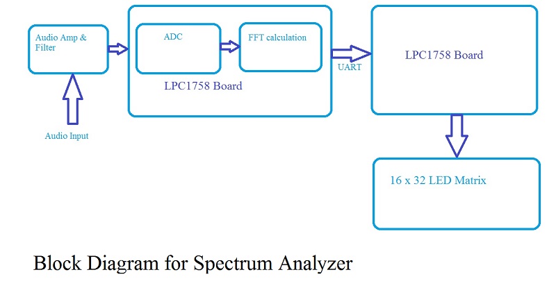
S14: Spectrum Analyzer for Audio Frequency Signals - Embedded ...
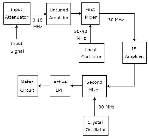
Spectrum Analyzer : Working Principle, Classfication & Its ... The block diagram of the spectrum analyzer is shown above. It consists of an input attenuator, which attenuates the input radio frequency signal. The attenuated signal is fed to a low pass filter to eliminate the ripple content. The filtered signal is mixed with a voltage tuned oscillator, and fed to an amplifier.
Basics of spectrum analyzers
PDF Real-Time Spectrum Analyzer Fundamentals This chapter contains several architectural diagrams of the main acquisition and analysis blocks of the Tektronix Real- Time Spectrum Analyzer (RTSA). Some ancillary functions have been omitted to clarify the discussion. Modern RTSAs can acquire a passband, or span, anywhere within the input frequency range of the analyzer.

Terminology Used in FFT Analyzers
APEX Technologies High resolution Optical Spectrum Analyzers. Discover the world best resolution Optical Spectrum Analyzer model with 5 MHz/40 fm optical bandwidth filter resolution. Tunable laser, DFB, power meter, variable attenuator, tunable filter, EDFA, switch
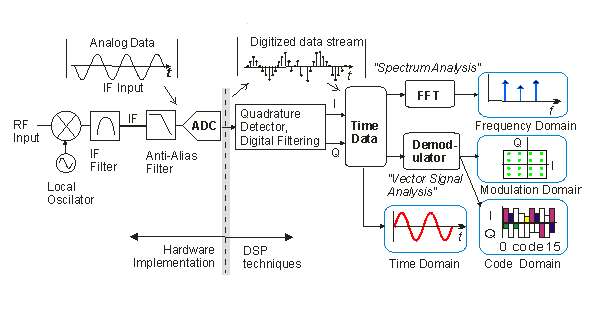
Vector signal analyzer - Wikiwand
PDF Tim Huang 2022.02 SWEPT SPECTRUM ANALYZER BLOCK DIAGRAM Pre-Selector or Low Pass Input Filter Crystal Reference Oscillator Log Amp RF Input Attenuator Mixer IF Filter (RBW) Envelope Detector Video Filter Local Oscillator Sweep Generator IF Gain Input signal Display
Spectrum Analyzer Block Diagram | Applications - EEEGUIDE.COM
PDF SPECTRUM ANALYZER - Bharath Institute of Higher Education ... A block diagram of an audio spectrum analyzer. SPECTRUM ANALYZERS •The real-time, or multichannel. analyzer is basically a set of stagger-tuned bandpass filters connected through an electronic scan switch to a CRT. The composite amplitude of the signal within each filters bandwidth is displayed as a ...

File:Signal analyzer block diagram.png - Wikipedia

Spectrum Analysis Basics - Part 2: What's in a spectrum ...

electronics Notes : Spectrum Analyzer :Introduction,types of ...

Real time spectrum analyzers vs. swept spectrum analyzers
Spectrum Analyzer Block Diagram | Applications - EEEGUIDE.COM
Project 136
Why Sweeping Spectrum Analyzer Circuit Needs More Than One LO?

Block diagram for a digital cross-correlation spectrum ...
Wave Analyzers
Spectrum analyzer - Wikipedia

Audio Spectrum Analyzer

Part 3: Overcoming RF/Microwave Interference Challenges in ...

Signal Analyzer Fundamentals and New Applications
.jpg)
Why and How to Use Spectrum Analyzers - Mega Depot
Spectrum Analyzer Tracking Generator » Electronics Notes

Optical Spectrum Analyzer function | OSA Application Note
SPECTRUM ANALYZER 9 kHz GHz - ppt download

Vector signal analyzer - Wikipedia
What is Spectrum Analyzer? Block Diagram, Working and ...
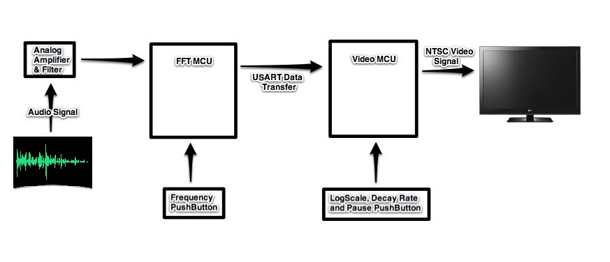
ECE 4760 Audio Spectrum Analyzer
Display frequency spectrum of time-domain signals - MATLAB

FFT Spectrum Analyzer: Fast Fourier Transform » Electronics Notes
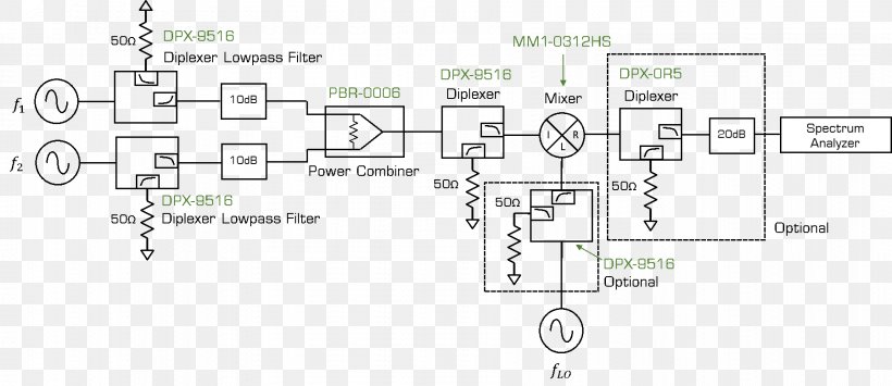
Frequency Mixer Spectrum Analyzer Third-order Intercept Point ...
0 Response to "42 spectrum analyzer block diagram"
Post a Comment