43 3 to 1 pulley system diagram
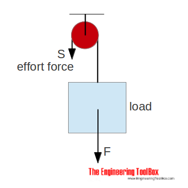
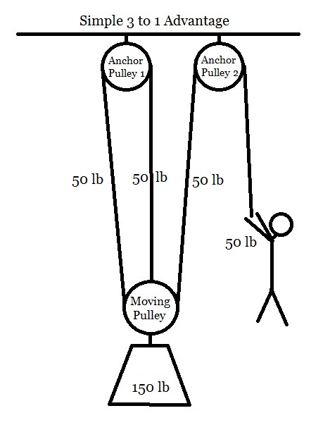
Rock Climbing Forums: Climbing Information: Beginners: 3:1 ... In the image above, the circles represent pulleys, and the three short bars represent the prussik. It's not a totally correct force diagram because tension in the rope is ignored, but it easily shows how the forces add up in a 3:1 system. So, I actually set up the pulley, and sure enough, I pulled Nine inches, and the weight moved 3. Overview of a simple pulley system - Alpine Savvy Let's break this down by starting at the beginning and then working up to a simple MA system, so you can really see how this works. The basic 1:1 pull Sticky the Climber needs to lift a 100 lb. load up to her ledge. She ties a rope onto the load, and starts pulling. To even budge it off the ground, she needs to pull up with 100 pounds of effort.
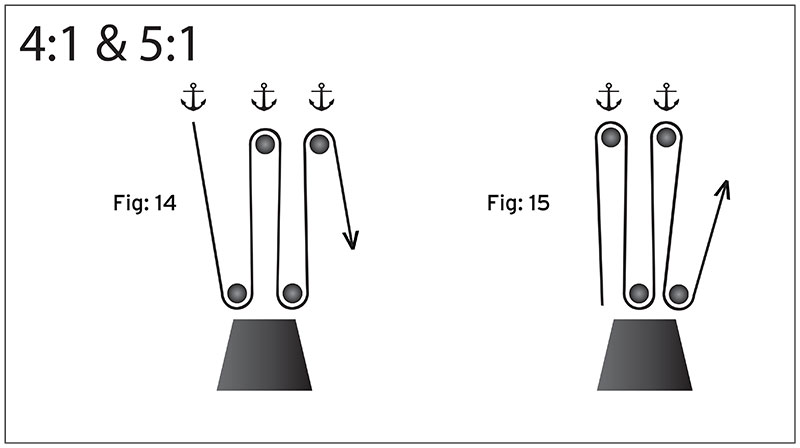
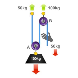
Pulley Systems - ropebook The 3:1 Pulley System . Here we have a 3:1 mechanical advantage. First one end of the rope is attached directly to the load, this is then passed around an. Read More » Pulley Systems. The 4:1 Pulley System . This pulley system provides a 4:1 mechanical advantage. The user is required to apply a force of 25kg to raise this 100kg load, for every

3 to 1 pulley system diagram
Mechanical Advantage of 3 Pulley System - Engineering ... So if you did a free body diagram on the following system by sectioning along the ropes: what you get from the equilibrium is $4F = 48[N]$. I hope that is sufficient as an explanation, I tend to find that problems with pulleys can have different configurations and as such it is always better to turn to the basics. Rope Pulley System Diagrams - 17 images - rope and pulley ... Rope Pulley System Diagrams - 17 images - how to build a pulley system for kayaks melisa, rope and pulley systems segment 6 the block and tackle, pulleys and lifting, 33 3 to 1 pulley system diagram wiring diagram database, homework and exercises pulley system with rope physics, Rope Pulley System Diagrams Willie Friday, March 25, 2022 Rope Rescue 3:1 System - Rope Rescue Training Rigging a 3:1 System. Some rescuers find it challenging to remember how to rig a 3:1 system. The following process may make it easier to remember: First rig a 1:1 system. The rope comes from the load and goes through one pulley. Easy enough. Now add "capture" Prusiks that will hold the load if you let go of the rope.
3 to 1 pulley system diagram. Mountaineers: Crevasse Rescue Using a Z-Pulley System (3 ... Demonstration of a climber extrication from a crevasse using a 3:1 z-pulley system (3-person rope team). Shot by ... PDF 4.3. Tension and Pulleys - Weebly Pulleys: Demonstration 1. How might a pulley change tension? 2. What would the free-body diagram of the balance of forces be for a rope and a pulley: a. For the rope turned 90 degrees? b. For the rope turned 180 degrees? 3. Experiment! PDF PULLEYS & THE 3:1 PULLEY SYSTEM © 1994 Cyril Shokoples The following diagrams of 3:1 Simple Pulley Systems have the pulleys labeled as 'A' and 'B'. By placing the pulley at 'B' you will make optimum use of the pulley and the resulting efficiency and Force Advantage Ratio will be maximized. PDF Activity 2.1.3 Free Body Diagrams Create a FBD for the pulley system pictured below. Different types of support reactions •Cable, rope, or chain •Pin •Roller •Built-in end -Cantilever Free Body Diagram Reactions To aid in completing free body diagrams, connections are often identified with letters Cable, rope, chain -Replace with a tension force only. Cable Support
Double Pulley System Diagram - how to set up a double ... Double Pulley System Diagram - 18 images - draw labelled diagrams of a single fixed pulley and a, diy pulley lift platform google search simple system for, mechanical advantage pulley, in the given figure pulley systems containing one two, The 3:1 Pulley System - ropebook An easy way to calculate the ratio of a pulley system is to count the amount of lines that apply effort on the load. In this system there are three ropes that exert effort on to a load of 90kg, so each rope is supporting 1/3 of the loads weight (30kg). Pulleys B & C and their anchors are subject to 60kg each. The 3:1 Pulley System 3:1 Pulley System - YouTube This video demonstrates how to set up a simple 3:1 pulley with a Petzl Reverso. Note that the Reverso acts as a 'progress capturing device' as it allows slac... Diagrams and Definitions of Pulleys For timing pulleys: For timing pulleys, this is the measurement between the flanges. Belts that fit: The belts, chains, or rope sizes that will fit into the pulley. For V-groove idlers and drives: A belt is considered to fit into a pulley if both the following are true:; The narrowest part of the belt does not touch the bottom of the V-groove.; At least 3/4 of the belt fits inside the groove ...
Solved 2 3 Figure 1. The physical setup of the pulley ... 2 3 Figure 1. The physical setup of the pulley system with its free body diagram. Given a set-up like that described in Figure 1 you measure 12-8N and θ2-1460 while 13-12N and θ3-270°. Determine what Ti and θι would have to be in order for the system to be in equilibrium (ie. The sum of the forces Ti, T2, and T3 on the knot needs to be zero) 3-Pulley system - Physics Forums 21. Question: Two pulleys of masses 12 kg and 8 kg are connected by a fine string hanging over a fixed pulley as shown. Over the 8 kg pulley is hung a fine string with masses 4 kg and M. Over the 12 kg pulley is hung another fine string with masses 3 kg and 6 kg. Calculate M so that the string over the fixed pulley remains stationary. PDF PULLEY ASSEMBLY DIAGRAMS - allpartsupply.com PULLEY ASSEMBLY DIAGRAMS ALLPART SUPPLY, INC. 1-800-381-1330 - Fax 817-284-2935© 2008 ALLPART SUPPLY, INC. PULLEY ASSEMBLY DIAGRAMS STANDARD WIDTH 168 - SHORT CROSSMEMBER PULLEY CROSSMEMBER CHANNEL GANG PULLEY LEFT REAR RUNWAY RUNWAY TOP Basic Pulley Mechanisms : 17 Steps (with Pictures ... Step 3: Calculating Speed Ratios for Pulleys. The Speed Ratio is the ratio of angular velocity of the input pulley of a system to the angular velocity of the output pulley. If you've calculated gear ratios, it is almost exactly the same! This is all based on a pulley's reference diameter, as defined below:
Rope Rescue 3:1 System
2:1 System - Rope Rescue Training This next system retains the COD pulley, but it "piggybacks" the 2:1 system onto another rope (i.e., in this illustration, the blue 2:1 system is piggybacked onto the yellow rope). The advantage of using a piggyback system (sometimes called a "pig rig") is that the pulley doesn't need to be attached to the load (which might be a long way from ...

A pulley system — Collection of Solved Problems
Ls1 Serpentine Belt Diagram - schematron.org Results 1 - 48 of Drive Belt & Pulley Kit Kit Contains: 1 x Tensioner Pulley 1 x Commodore VT VX VY VZ V8 GEN 3 LS1 2 Drive Belts and 4 pulleys Kit. I checked, it is indeed a 15mm head, you only have to move the bottom tensioner. Turn it downward, and then refer to your belt diagram and put. C5 Tech - I have a serpentine belt routing diagram..

In the pulley system shown, if radii of the bigger and ...
How to Calculate First, Second and Third Pulley Systems ... First System of Pulleys As can be seen from the diagram, the lowermost pulley here carries the load (being lifted), which is fixed and hangs over the axle of the pulley. An end of the string T1 attached firmly to an upper rigid frame, passes across the groove of this pulley and attaches its other to the axle of the second.
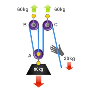
The 3:1 Pulley System - ropebook
diagram of a basic 3:1 redirect pulley system | Pulley ... The 4:1 Pulley System - ropebook This pulley system provides a 4:1 mechanical advantage. The user is required to apply a force of 25kg to raise this 100kg load, for every…
Mechanical Advantage Systems 1
System of Pulleys — Mechanical Advantage Calculator ... A pulley is a simple machine in the form of a wheel with a groove between flanges mounted on an axle that is used to guide a line (a rope or a cable) around it or support its movement. The wheel with a groove is called a sheave or pulley wheel. The sheave is installed on an axle, sometimes with a bearing, inside the pulley case.
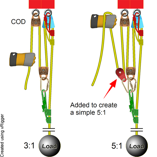
Rope Rescue 5:1 System
PPT How to diagram a pulley system! - cdschools.org How to diagram a pulley system! Anchor point The anchor point should be a solid black box fixed to a surface. Dot Draw a large dot to show where the end of the rope is connected. Rope Use a nice black line to represent the ropes. Pulley Use a larger circle with a dot in the middle to represent the pulley.

Diagram of a pulley system with arrows | Download Scientific ...
84 Pulley systems ideas | pulley, block and tackle, pully ... Jul 5, 2021 - Explore Bob DeFoor's board "Pulley systems", followed by 170 people on Pinterest. See more ideas about pulley, block and tackle, pully system.

Overview of a simple pulley system — Alpine Savvy
PDF Rescue Pulley System Rigging Diagrams April 25th, 2018 - PULLEYS amp THE 3 1 PULLEY SYSTEM Other special purpose rescue pulleys for bypassing knots or minding prusiks The following diagrams of 3 1 Simple Pulley Systems''Rescue Pulley System Rigging

Block and Tackle Pulley System | Options and Modeling ...
PATC-MS - A More Efficient 3:1 Pulley System Description (limit to 200 words): At the recent "Leader's SKill Day" at Carderock, Md. on 4/10/10 we showed PATC members how to construct a 3:1 pulley system in the event they needed to help/aid a stuck "second" having trouble on the crux. With any system there are pros and cons.

Mechanical Advantage Explained | Educated Climber.com
Block and Tackle Rigging Diagram [+ Examples] | EdrawMax All you need to do is select any software and follow the steps of drawing block and tackle rigging diagram. Step 01 Download and open EdrawMax in your pc. Step 02 Select an empty canvas where you can make your diagram. Or, nagivate to [Science and Education] > [Mechanics], find and open a template. Step 03

Pulley system composition – a systematic approach
Pulleys and Mechanical Advantage Systems | CMC PRO Compound pulley systems are created when a simple pulley system is pulling on another simple pulley system. By adding a 2:1 mechanical advantage to a 3:1 mechanical advantage system you compound, or multiply, the mechanical advantage and end up with a 6:1. A 3:1 pulling on another 3:1 gives you a mechanical advantage of 9:1.
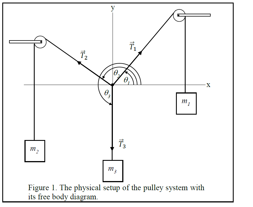
Solved 2 3 Figure 1. The physical setup of the pulley system ...
Rope Rescue 3:1 System - Rope Rescue Training Rigging a 3:1 System. Some rescuers find it challenging to remember how to rig a 3:1 system. The following process may make it easier to remember: First rig a 1:1 system. The rope comes from the load and goes through one pulley. Easy enough. Now add "capture" Prusiks that will hold the load if you let go of the rope.
Pulleys
Rope Pulley System Diagrams - 17 images - rope and pulley ... Rope Pulley System Diagrams - 17 images - how to build a pulley system for kayaks melisa, rope and pulley systems segment 6 the block and tackle, pulleys and lifting, 33 3 to 1 pulley system diagram wiring diagram database, homework and exercises pulley system with rope physics, Rope Pulley System Diagrams Willie Friday, March 25, 2022

Mechanical Advantage Explained | Educated Climber.com
Mechanical Advantage of 3 Pulley System - Engineering ... So if you did a free body diagram on the following system by sectioning along the ropes: what you get from the equilibrium is $4F = 48[N]$. I hope that is sufficient as an explanation, I tend to find that problems with pulleys can have different configurations and as such it is always better to turn to the basics.

The Problem with Pulleys | Carolina.com
Mechanical Advantage Explained | Educated Climber.com

System of Pulleys — Mechanical Advantage Calculator ...

Washing Line Pulley System Diagram | Washing line, Pulley ...
DMM Professional - Resistance is futile

Pulleys and Mechanical Advantage Systems | CMC PRO
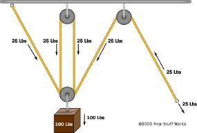
How a Block and Tackle Works | HowStuffWorks

Pulleys – Simple Machines for Kids – Inventors of Tomorrow
What is the mechanical advantage of a pulley that has 3 ...

3-1 pulley systen setup or Z-rig (SMARTER NOT HARDER)
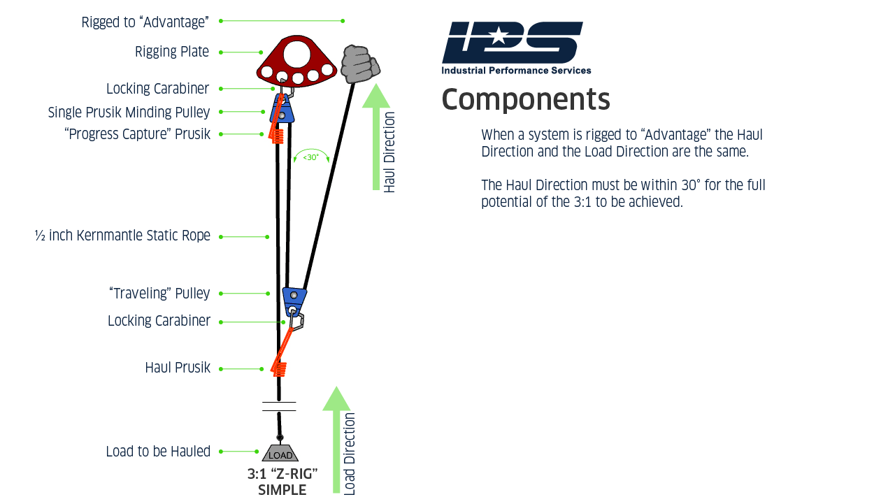
Z-Rig Construction – Safety, Rescue, Training, Catalyst and ...
The 2:1 Pulley System - ropebook

Using carabiners as pulleys
Self rescue hauling

classical mechanics - Compound mechanical advantage ...

Solved PRE-LAB 4: Simple Machines 1. (3 pts) Draw a | Chegg.com

A Single Movable Pulley and Mechanical Advantage | Science ...
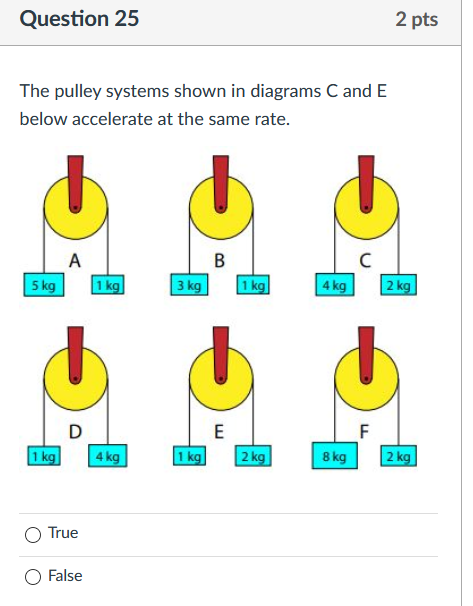
Solved Question 25 2 pts The pulley systems shown in | Chegg.com
Mechanical Advantage Systems 1
Pulleys and Lifting - Question 1
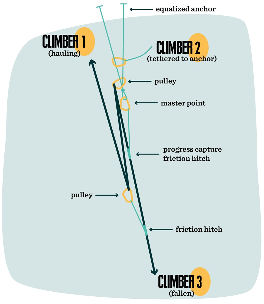
Crevasse Rescue Skills | REI Co-op

How to set up a Z-Drag System | Rope Knots by NetKnots

Simple machines
Pulley system efficiency tests with MAESTRO, I'D S, PRO ...

Mechanical Advantages #3 Pulley Systems Explained: Hansen ...
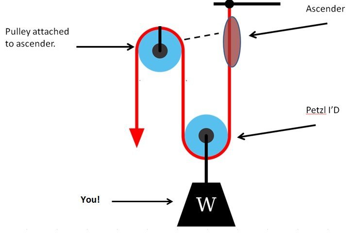
Ascending with I'D

Mechanical Advantage Explained | Educated Climber.com

System of Pulleys — Mechanical Advantage Calculator ...
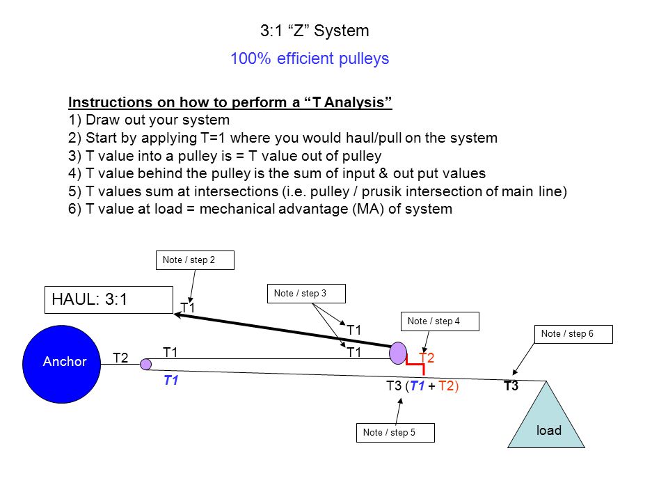
3:1 “Z” System 100% efficient pulleys Instructions on how to ...
0 Response to "43 3 to 1 pulley system diagram"
Post a Comment