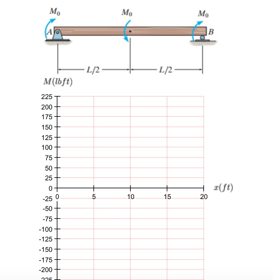
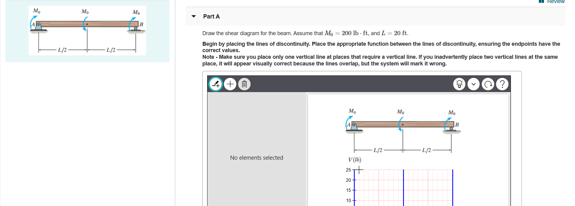
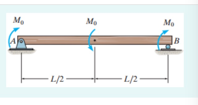
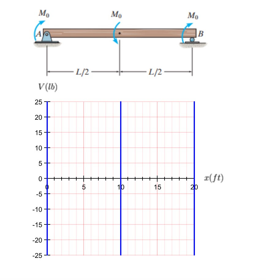
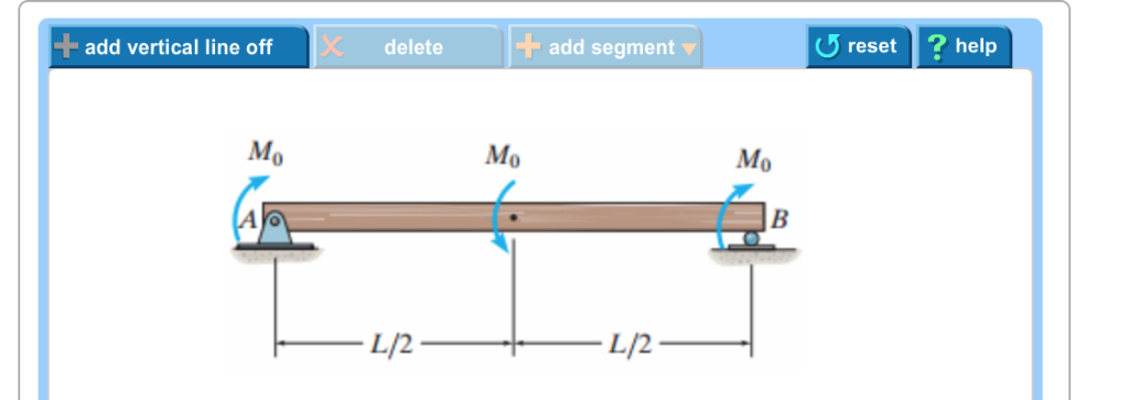
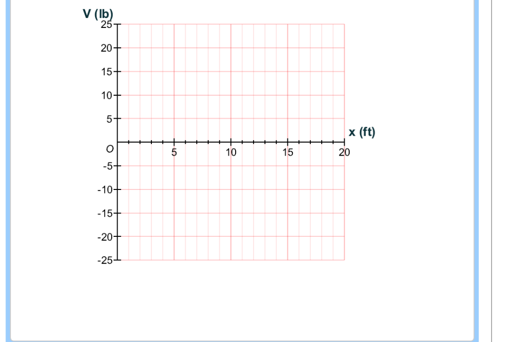
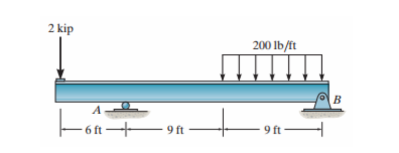
44 draw the shear diagram for the beam. assume that m0=200lb⋅ft, and l=20ft.
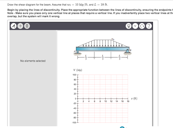
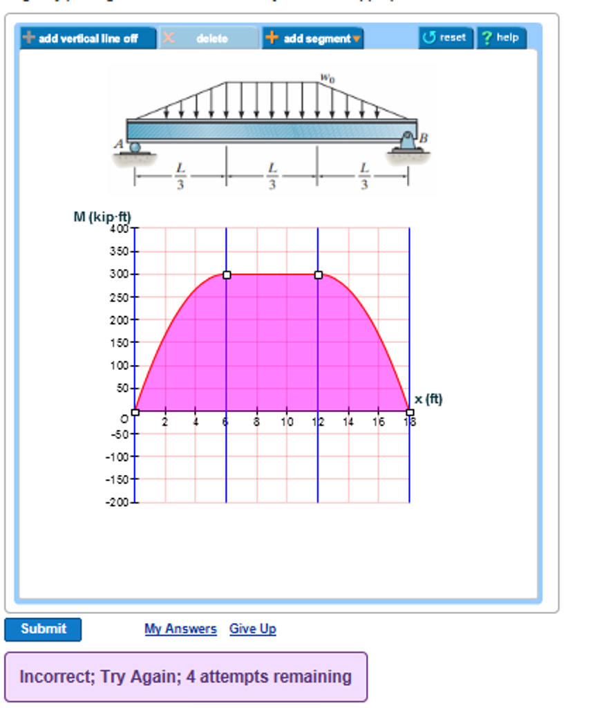
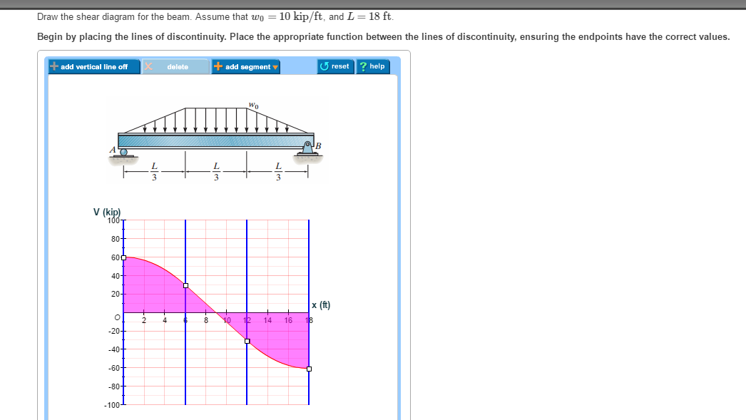
Solved Draw the shear diagram for the beam. Assume that w 0 ... See the answer. See the answer See the answer done loading. Draw the shear diagram for the beam. Assume that w 0 =10kip/ft , and L=18ft. Draw the moment diagram for the beam. Assume that w 0 =10kip/ft , and L=18ft. Show transcribed image text. Expert Answer. Solved Draw the shear diagram for the beam. Assume that ... Draw the shear diagram for the beam. Assume that M 0=200lb⋅ft, and L =20ft. Show transcribed image text. Expert Answer. Who are the experts? Experts are tested by Chegg as specialists in their subject area. We review their content and use your feedback to keep the quality high. 100% (5 ratings)
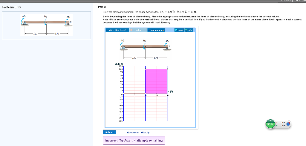
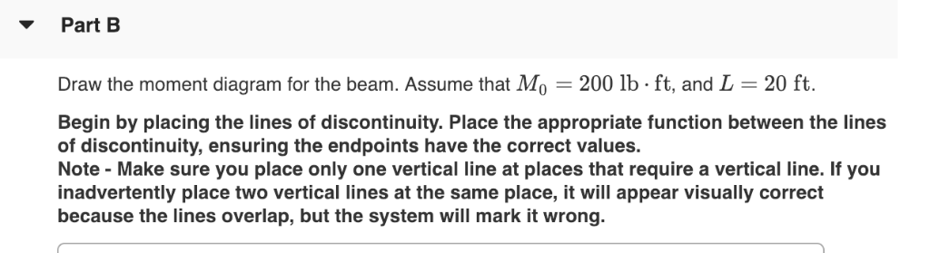
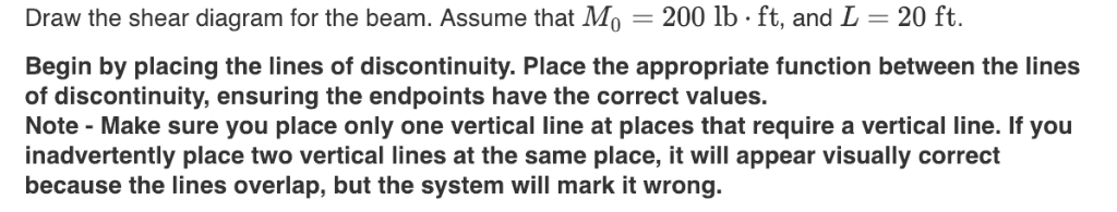
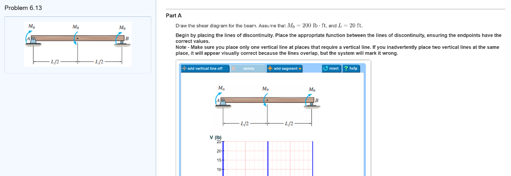
45 draw the shear diagram for the beam. assume that m0=200lb⋅ ... Dec 24, 2021 · Draw the shear diagram for the beam. Assume that M0=200lb⋅ft, and L=20ft. Begin by placing the lines of discontinuity. Place the appropriate function between the lines of discontinuity, ensuring the endpoints have the correct values. Note - Make sure you place only one vertical line at places that require a vertical line.
Draw the shear diagram for the beam. assume that m0=200lb⋅ft, and l=20ft.
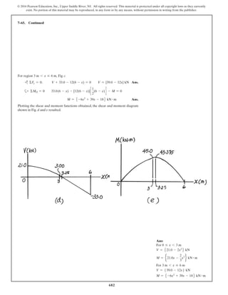
Hibbeler Chapter 6 Part 1 (463-486) - Auburn University Draw the shear and moment diagrams for the beam and determine the shear and moment in the beam as functions of x, where 4 ft < x < 10 ft. 200 lb ft B x 4 ft 4 ft 150 lb/ft 6 ft 200 lb ft A Ans. a M =-75x2 + 1050x - 3200 Ans.-200 - 150(x - 4) (x - 4) 2 +©M = 0; - M + 450(x - 4) = 0 V = 1050 - 150x + c©F y = 0;-150(x - 4) - V + 450 = 0 M (lb ft) V (lb) 200 200 450 475 450 x x Ans: Free Online Beam Calculator | SkyCiv Engineering Free online beam calculator for generating the reactions, calculating the deflection of a steel or wood beam, drawing the shear and moment diagrams for the beam. This is the free version of our full SkyCiv Beam Software. This can be accessed under any of our Paid Accounts, which also includes a full structural analysis software. Solved Problem 6.13 Part A Draw the shear diagram for the ... Transcribed image text: Problem 6.13 Part A Draw the shear diagram for the beam. Assume that Mo 200 lb.ft, and L 20 ft. Begin by placing the lines of discontinuity. Place the appropriate function between the lines of discontinuity, ensuring the endpoints have the correct values Note Make sure you place only one vertical line at places that require a vertical line.
Draw the shear diagram for the beam. assume that m0=200lb⋅ft, and l=20ft.. Solved Draw the shear diagram for the beam. Assume that ... Draw the shear diagram for the beam. Assume that M0=200lb⋅ft, and L=20ft. Begin by placing the lines of discontinuity. Place the appropriate function between the lines of discontinuity, ensuring the endpoints have the correct values. Note - Make sure you place only one vertical line at places that require a vertical line. PDF Chapter 4 Shear and Moment In Beams - ncyu.edu.tw 4.3 Shear- Moment Equations and Shear-Moment Diagrams The determination of the internal force system acting at a given section of a beam : draw a free-body diagram that expose these forces and then compute the forces using equilibrium equations. The goal of the beam analysis -determine the shear force V and Solved Draw the shear diagram for the beam. Assume that ... Draw the shear diagram for the beam. Assume that M0=200lb⋅ft, and L=20ft. Begin by placing the lines of discontinuity. Place the appropriate function between the lines of discontinuity, ensuring the endpoints have the correct values. Note - Make sure you place only one vertical line at places that require a vertical line. If you. Solved Problem 6.13 Part A Draw the shear diagram for the ... Transcribed image text: Problem 6.13 Part A Draw the shear diagram for the beam. Assume that Mo 200 lb.ft, and L 20 ft. Begin by placing the lines of discontinuity. Place the appropriate function between the lines of discontinuity, ensuring the endpoints have the correct values Note Make sure you place only one vertical line at places that require a vertical line.
Free Online Beam Calculator | SkyCiv Engineering Free online beam calculator for generating the reactions, calculating the deflection of a steel or wood beam, drawing the shear and moment diagrams for the beam. This is the free version of our full SkyCiv Beam Software. This can be accessed under any of our Paid Accounts, which also includes a full structural analysis software. Hibbeler Chapter 6 Part 1 (463-486) - Auburn University Draw the shear and moment diagrams for the beam and determine the shear and moment in the beam as functions of x, where 4 ft < x < 10 ft. 200 lb ft B x 4 ft 4 ft 150 lb/ft 6 ft 200 lb ft A Ans. a M =-75x2 + 1050x - 3200 Ans.-200 - 150(x - 4) (x - 4) 2 +©M = 0; - M + 450(x - 4) = 0 V = 1050 - 150x + c©F y = 0;-150(x - 4) - V + 450 = 0 M (lb ft) V (lb) 200 200 450 475 450 x x Ans:
SOLUTION
Untitled
Solved Draw the shear diagram for the beam. Assume that ...
329 6–1. Draw the shear and moment diagrams for the shaft ...
Mechanics of Materials Chapter 4 Shear and Moment In Beams
Mechanics of Materials Chapter 4 Shear and Moment In Beams
Solved Problem 6.13 Part A Draw the shear diagram for the ...

MECHANICS OF MATERIALS Pages 201-250 - Flip PDF Download ...
Mechanics of Materials Chapter 4 Shear and Moment In Beams
Solved 1 Review Part A 12—A L Draw the shear diagram for the ...

Drawing Shear and Moment Diagrams for Beam - YouTube
PROBLEM 5.1

Please answer this question in one hour. Problem 6.13 Part A ...
Solved Draw the shear diagram for the beam. Assume that ...
Chapter 7
Solved Draw the shear diagram for the beam. Assume that ...
SOLUTION
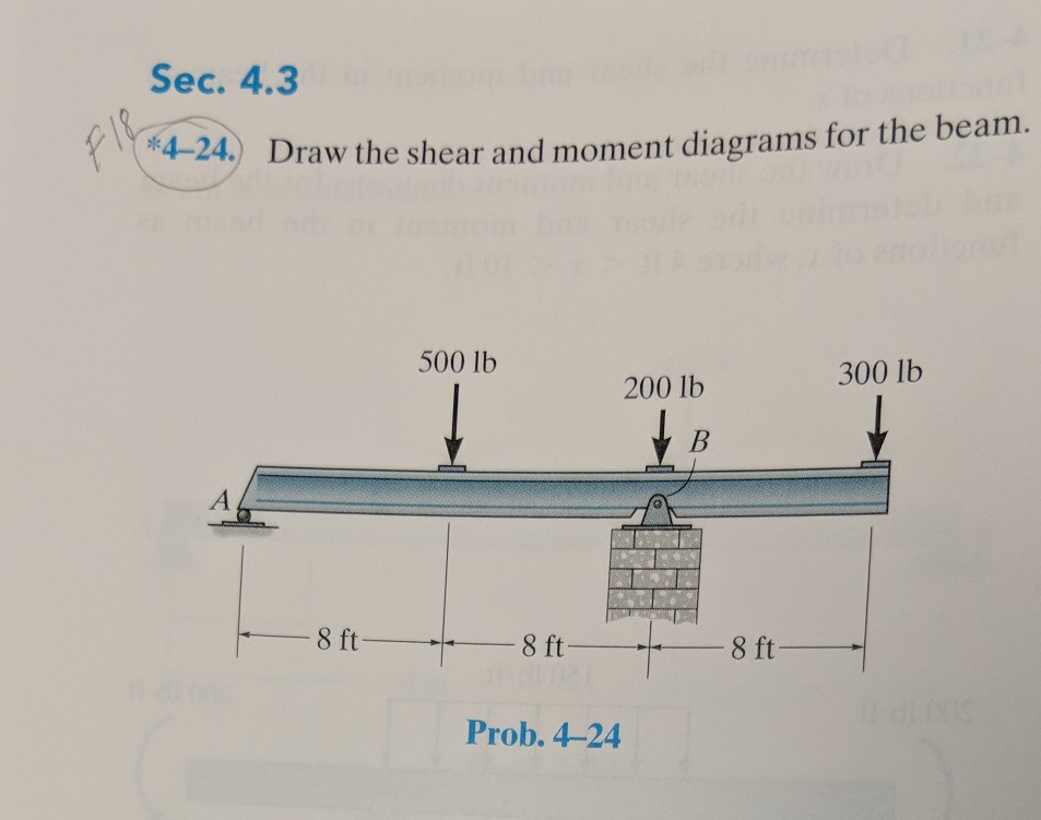
Solved Sec. 4.3 4- 24,) Draw the shear and moment diagrams ...
Problem 7-1 The column is fixed to the floor and is subjected ...

Solved Draw the shear and moment diagrams for the beam ...
Vector Mechanics for Engineers Statics by Ferdinand P. Beer E ...
Solved] Can you help me this 1 to 4? | Course Hero

ENGINEERING MECHANICS STATICS Pages 351-400 - Flip PDF ...
Solved Draw the shear diagram for the beam. Assume that wo ...
Solved Part B Draw the moment diagram for the beam. Assume ...
Solved Part B Draw the moment diagram for the beam. Assume ...

329 6–1. Draw the shear and moment diagrams for ...

Please answer this question in one hour. Problem 6.13 Part A ...
Solved Part B Draw the moment diagram for the beam. Assume ...
Solved Part B Draw the moment diagram for the beam. Assume ...
Solved Draw the shear diagram for the beam. Draw the | Chegg.com

PDF) PROBLEM 7.1 | Ghabriel Barbieri Molinarolli - Academia.edu
329 6–1. Draw the shear and moment diagrams for the shaft ...
Problem 7-1 The column is fixed to the floor and is subjected ...
Solved Problem 6.13 Part A Draw the shear diagram for the ...
Solved Draw the shear diagram for the beam. Assume that w 0 ...
Solved Draw the shear diagram for the beam. Assume that wo ...
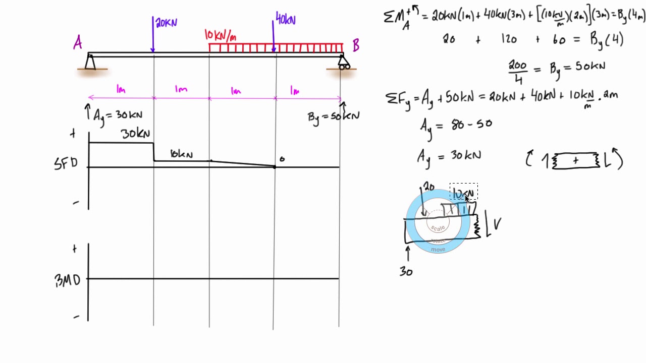
Shear force and bending moment diagram example #5: mixed distributed and point loads
329 6–1. Draw the shear and moment diagrams for the shaft ...
Hibbeler R.C. Structural Analysis

Drawing Shear and Moment Diagrams for Beam

Solved) - Draw the shear diagram and the moment diagram for ...

Draw the shear and moment diagrams for the beam. Assume the ...
329 6–1. Draw the shear and moment diagrams for the shaft ...
0 Response to "44 draw the shear diagram for the beam. assume that m0=200lb⋅ft, and l=20ft."
Post a Comment