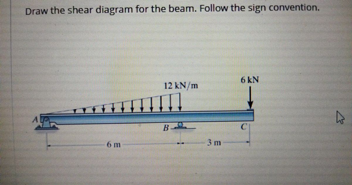
43 draw the shear diagram for the beam. follow the sign convention. (figure 1)
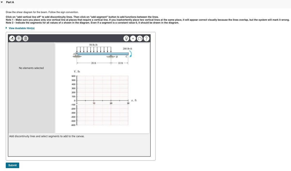
Solved Problem 7.59 Part A Draw the shear diagram for the ... Question: Problem 7.59 Part A Draw the shear diagram for the beam. Follow the sign convention. (Figure 1) Click on 'add vertical line off to add discontinuity lines. Then click on "add segment" button to add functions between the lines. Note 1 - You should not draw an "extra" discontinuity line at the point where the curve passes the x-axis. Answered: Draw the shear diagram for the beam.… | bartleby Draw the shear diagram for the beam. Follow the sign convention. (Figure 1) Click on "add vertical line off" to add discontinuity lines. Then click on "add segment" button to add functions between the lines. Note - The curve you choose from the drop-down is only a pictorial representation of a real quadratic/cubic curve.
Draw the shear diagram for the beam. follow the sign ... Draw the shear diagram for the beam. Follow the sign convention. (Figure 1) Click on "add vertical line off" to add discontinuity lines. Then click on "add segment" button to add functions between the lines. Note 1 - You should not draw an "extra" discontinuity line at the point where the curve passes the x-axis.
Draw the shear diagram for the beam. follow the sign convention. (figure 1)
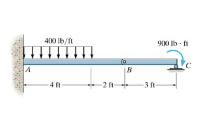
Part A Draw the shear diagram for the beam. Follow the sign Share With Part A Draw the shear diagram for the beam. Follow the sign convention. (Figure 1) Click on "add vertical line off" to add discontinuity lines. Then click on "add segment" button to add functions between the lines. The And For Below Beams Draw Diagrams Moment Shear Shown ... A M/EI diagram is a moment diagram divided by the beam's Young's modulus and moment of inertia. Problem 407 Beam loaded as shown in Fig. Problem 5-4. " The conjugate beam is "loaded" with the M/EI diagram. Draw the shear diagram for the beam follow the sign convention figure 1. Draw the bm diagram consistently on the tension side. Consider the frame shown in (Figure 1). Follow the sign ... Consider the frame shown in (Figure 1). Follow the sign convention. Figure Part A Draw the shear diagram for member AB. Follow the sign convention for the internal loadings in the member shown in the figure below. Click on "add vertical line off" to add discontinuity lines. Then click on "add segment" button to add functions between the lines. Note - Make sure you place only one vertical line ...
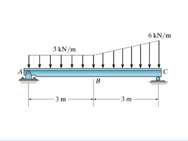
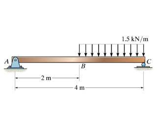
Draw the shear diagram for the beam. follow the sign convention. (figure 1). Part A Consider the beam shown in (Figure 1). Follow the ... Part A Consider the beam shown in (Figure 1). Follow the sign convention. Draw the shear diagram for the beam Click on "add vertical line off" to add discontinuity lines. Then click on "add segment" button to add functions between the lines. Note 1-You should not draw an "extra" discontinuity line at the point where the curve passes ... Solved Problem 7.56 Part A Draw the shear diagram - Chegg Problem 7.56 Part A Draw the shear diagram for the beam. Follow the sign convention. (Figure 1) Part B Draw the moment diagram for the beam. Follow the sign convention. Show transcribed image text Expert Answer 100% (11 ratings) Transcribed image text: 1.5 kN/m 2 m 4 Previous question Next question Statics 7.71 - Draw the shear and moment diagram for the beam. Question: Draw the shear and moment diagram for the beam.Problem 7-71 from:Engineering Mechanics: Statics, 14th editionRussell C. HibbelerThank you guys for ... Answered: Part A Draw the shear diagram for the… | bartleby Part A Draw the shear diagram for the beam. Follow the sign convention. (Figure 1) Click on "add vertical line off" to add discontinuity lines. Then click on "add segment" button to add functions between the lines. Note - Make sure you place only one vertical line at places that require a vertical line.
[Solved] Please see attachments for details | Course Hero Part A Draw the shear diagram for the beam. Follow the sign convention. (Figure 1)... (Solved) - Draw the shear diagram for the beam. Follow the ... 1 Answer to Draw the shear diagram for the beam. Follow the sign convention. (Figure 1) Draw the moment diagram for the beam. Follow the sign convention. 2 m. 15 kN 200 kN m 1 m. 1 m 10 kN/m 2 m Answered: Draw the shear diagram for the beam.… | bartleby Draw the shear diagram for the beam. Follow the sign convention. (Figure 1) Click on "add vertical line off" to add discontinuity lines. Then click on "add segment" button to add functions between the lines. Note 1- You should not draw an "extra" discontinuity line at the point where the curve passes the x-axis. Answered: Draw the shear diagram for the beam.… | bartleby Draw the shear diagram for the beam. Follow the sign convention. (Figure 1) Click on "add vertical line off" to add discontinuity lines. Then click on "add segment" button to add functions between the lines. Note 1 - Make sure you place only one vertical line at places that require a vertical line.
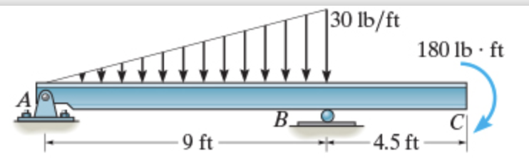
Part A Draw the shear diagram for the beam. Follow the ... Figure (< 1 of 1 > 30 lb/ft 180 lb. ft AC Part A Draw the shear diagram for the beam. Follow the sign convention. (Figure 1) Click on "add vertical line off to add discontinuity lines. (Solved) - Consider the beam shown in (Figure 1) . Follow ... 1 Answer to Consider the beam shown in (Figure 1) . Follow the sign convention. Draw the shear diagram for the beam. Draw the bending moment diagram for the beam. 2 k 2k 2 k 2k 4 ft 4 ft 4 ft 4 ft 4 ft Draw the shear diagram for the beam. Follow the sign convent Draw the moment diagram for the beam. Follow the sign convention. The wrong answers keep getting posted. On the sheer diagram the values tested are A=12, Midpoint=7.5, B=3 On the moment diagram the values are A=-22.5, Midpoint=-6.75, B=0 I have tested both concave up and concave down in these scenarios. Both being wrong. No clue what is missing. Consider the beam in (Figure 1). Figure 50 kip ft -10 ... Civil Engineering questions and answers. Consider the beam in (Figure 1). Figure 50 kip ft -10 ft + 2 kip/ft -20 ft BAA -10 ft 1 of 1 50 kip ft Part A Draw the shear diagram for the beam. Follow the sign convention. Click on "add vertical line off" to add discontinuity lines. Then click on "add segment" button to add functions between the lines.
A distributed load on the beam exists due to the weight of ...
Draw the shear diagram for the compound beam which is pin ... Problem 7.70 Draw the shear diagram for the beam. Follow the sign convention. (Figure 1) Click on "add vertical line off" to add discontinuity lines. Then click on "add segment" button to add functions between the lines add vertical...

Applied Sciences | Free Full-Text | Nonlinear Finite Element ...
(Solved) - Draw the shear diagram for the beam. Follow the ... Draw the shear diagram for the beam. Follow the sign convention. (Figure 1) Draw the moment diagram for the beam. Follow the sign convention. 15 kN 10 kN/m 20 kN mm 2 m 2 m 1 Approved Answer HARSH answered on January 21, 2021 5 Ratings, ( 18 Votes) solution .pdf Do you need an answer to a question different from the above? Ask your question!
Answered: Draw the shear diagram for the beam.… | bartleby
Solved Problem 7.77 Part A Draw the shear diagram for the ... Transcribed image text: Problem 7.77 Part A Draw the shear diagram for the beam. Follow the sign convention. (Figure 1) Click on "add vertical line off" to add discontinuity lines.
Solved Draw the shear diagram for the beam. Follow the ...
(Solved) - Draw the moment diagram for the beam. Follow ... Draw the moment diagram for the beam. Follow the sign convention. (Figure 1)Click on "add vertical line off" to add discontinuity lines. Then click on "add segment" button to add functions between the lines. Note 1 - You should not draw an "extra" discontinuity line at the point where the curve passes the x-axis.

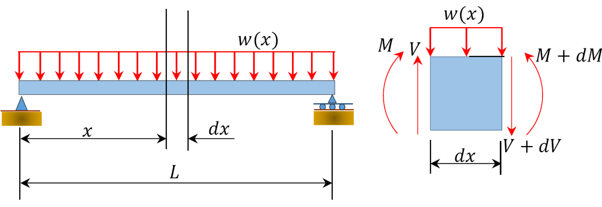
Determine the shear and moment along the beam as functions of ...
Consider the frame shown in (Figure 1). Follow the sign ... Consider the frame shown in (Figure 1). Follow the sign convention. Figure Part A Draw the shear diagram for member AB. Follow the sign convention for the internal loadings in the member shown in the figure below. Click on "add vertical line off" to add discontinuity lines. Then click on "add segment" button to add functions between the lines. Note - Make sure you place only one vertical line ...
Chapter 4: Internal Forces in Beams and Frames” in ...
The And For Below Beams Draw Diagrams Moment Shear Shown ... A M/EI diagram is a moment diagram divided by the beam's Young's modulus and moment of inertia. Problem 407 Beam loaded as shown in Fig. Problem 5-4. " The conjugate beam is "loaded" with the M/EI diagram. Draw the shear diagram for the beam follow the sign convention figure 1. Draw the bm diagram consistently on the tension side.

Part A Draw the shear diagram for the beam. Follow the ...
Part A Draw the shear diagram for the beam. Follow the sign Share With Part A Draw the shear diagram for the beam. Follow the sign convention. (Figure 1) Click on "add vertical line off" to add discontinuity lines. Then click on "add segment" button to add functions between the lines.

Chapter zero four - Mechanics of Materials Chapter 4 Shear ...
Solved Draw the shear diagram for the beam. Follow the ...

Statics 7.71 - Draw the shear and moment diagram for the beam ...
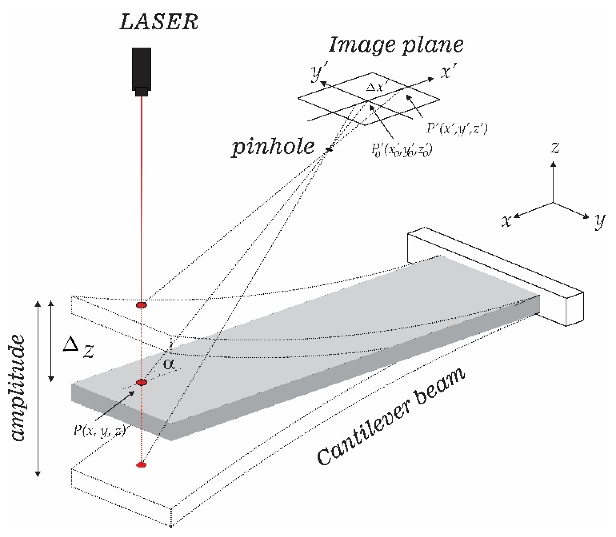
Symmetry | Free Full-Text | Vibration Measurement Using Laser ...

An application of extensions of the Ramo-Shockley theorem to ...
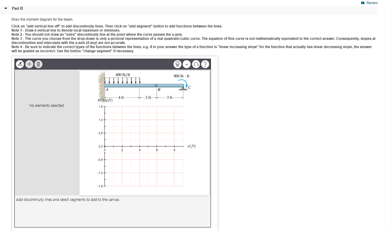
Solved: MI Review Part A Draw the shear diagram for the b
6.2 Shear/Moment Diagrams – Engineering Mechanics: Statics
Answered: Draw the shear diagram for the beam.… | bartleby

STRUCTURAL ANALYSIS USING ROBOT - YouTube

Solved) - Problem 7.88 Part A Draw the shear diagram for the ...

Draw the shear diagram for the beam. follow the sign ...
Lame de taille-haies
Solved Part A Draw the shear diagram for the beam. Follow ...
Solved Problem 7.56 Part A Draw the shear diagram | Chegg.com
Section 4.10

A review on metallurgical aspects of laser additive ...
Solved Problem 7.90 Part A Draw the shear diagram for the ...

PART A Draw the shear diagram for the beam. Follow the sign ...

Determine the internal moments at the supports for the beam ...
The Ultimate Guide to Shear and Moment Diagrams ...

For the figure below, draw: a) Draw the shear diagram for the ...

Draw the shear diagram for the beam. follow the sign ...

For the Figure below, determine: Part A Draw the shear ...
7.6: Deflection by the Conjugate Beam Method - Engineering ...

Draw the shear diagram for the beam. follow the sign ...
a) Draw the shear diagram for the beam shown in the sketch ...

The Ultimate Guide to Shear and Moment Diagrams ...

internal forces compound beam spr18 - YouTube
6.2 Shear/Moment Diagrams – Engineering Mechanics: Statics

Solved) - Draw the shear diagram for the beam. Follow the ...
Solved] Problem 7.84 Draw the shear diagram for the beam ...
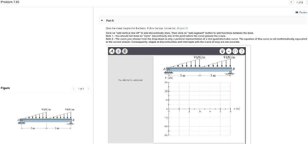
Solved Problem 7.83 I Review Part A Draw the shear diagram ...

Air entrainment and flow bulking in the numerical model for q ...

Solved) - Part A Draw the shear diagram for the beam Part B ...
Answered: Draw the shear diagram for the beam.… | bartleby
6.2 Shear/Moment Diagrams – Engineering Mechanics: Statics
0 Response to "43 draw the shear diagram for the beam. follow the sign convention. (figure 1)"
Post a Comment