43 rlc circuit phasor diagram
Chapter 12.3 - Phasor Diagram of Series RLC Circuit Chapter 12.3 - Phasor Diagram of Series RLC Circuit ... frequency f of the applied signal in relation to the frequency of resonance f0. Three different cases may ... Driven RLC Circuit Using Phasors - GeoGebra Driven RLC Circuit Using Phasors. Author: Dave Nero. Instructions. This simulation shows the phasor representation of a series RLC circuit. Adjust the values of R, L, and C using the sliders. Change how the circuit is driven by adjusting the emf amplitude and driving frequency. Use the check boxes to select which graphs are shown.
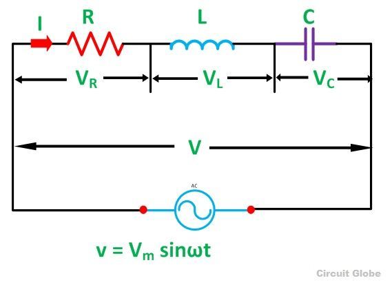
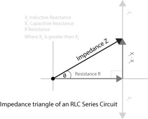
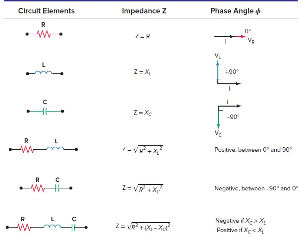
What is RLC Series Circuit? - Phasor Diagram ... Steps to draw the Phasor Diagram of the RLC Series Circuit; Phase Angle; Power in RLC Series Circuit; Impedance Triangle of RLC Series Circuit; The RLC Circuit is shown below: In the RLC Series circuit. X L = 2πfL and X C = 1/2πfC. When the AC voltage is applied through the RLC Series circuit the resulting current I flows through the circuit, and thus the voltage across each element will be:
Rlc circuit phasor diagram
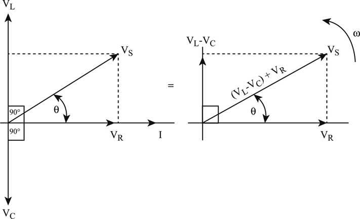
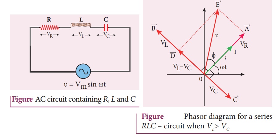
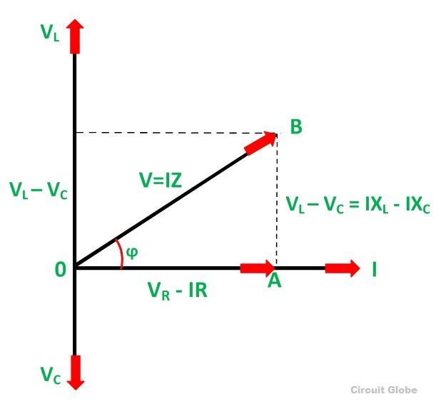
RLC Series Circuit - Georgia State University RLC Series Circuit. The RLC series circuit is a very important example of a resonant circuit.It has a minimum of impedance Z=R at the resonant frequency, and the phase angle is equal to zero at resonance.. One way to visualize the behavior of the RLC series circuit is with the phasor diagram shown in the illustration above. The phasor diagram shown is at a frequency where the inductive ... Series RLC Circuit Impedance Calculator • Electrical, RF ... The phasor diagram shows the V T voltage of the ideal sine voltage source. The voltage drop on the resistor V T is shown on the horizontal axis in phase with the current that flows through the circuit. The inductance voltage vector V L lags the current in the inductance vector by 90°, therefore it is drawn at +90°. What is RLC Series Circuit? - Phasor Diagram & Impedance PHASOR DIAGRAM OF RLC SERIES CIRCUIT As seen from the phasor diagram that Vₗ and Vc are 180 degree out of phase, they are direct opposite to each other. So effective voltage will be (Vₗ-Vc). Applied voltage is phasor sum of the voltage across resistance & effective voltage. V = √ { (Vr)² + (Vₗ -Vc)²} V = √ { (I*R)² + (I*Xₗ - I*Xc)²}
Rlc circuit phasor diagram. What is RL in circuit diagram? - Yemialadeworld.com A first-order RL circuit is composed of one resistor and one inductor and is the simplest type of RL circuit. How do you draw a RL circuit? Steps to draw the Phasor Diagram of RL Series Circuit The Voltage drop across the resistance VR = IR is drawn in phase with the current I. The voltage drop across the inductive reactance VL =IXL is drawn ... Phasor diagram for a series RLC circuit - BrainKart 25 Nov 2016 — Phasor diagram for a series RLC circuit · Consider a circuit in which R, L, and C are connected in series with each other across ac supply as ... Phasor Diagram for Series RLC Circuits - Wolfram Cloud WOLFRAM | DEMONSTRATIONS PROJECT. P h a s o r D i a g r a m f o r S e r i e s R L C C i r c u i t s. f r e q u e n c y f i n H z Phasor Diagram of Series RLC Circuit - YouTube Network Theory: Phasor Diagram of Series RLC Circuit Topics discussed:1) Phasor diagram of series RLC circuit.2) Voltage triangle of series RLC circuit.3) Im...
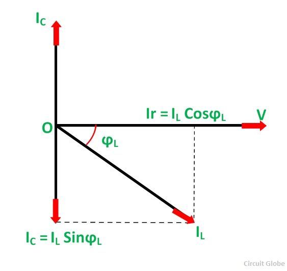
What is RC Series Circuit? Phasor Diagram and Power Curve ... The phasor diagram of the RC series circuit is shown below: Steps to draw a Phasor Diagram The following steps are used to draw the phasor diagram of RC Series circuit Take the current I (r.m.s value) as a reference vector Voltage drop in resistance VR = IR is taken in phase with the current vector Phasor diagrams and RLC curcuits | All About Circuits several phasor diagrams can be plotted. and the nice thing is that once theta is found for one, it will be the same for all. imagine an x y graph: x axis on horizon with positive to the right, and y axis on the vertical with positive to the top. the positive x axis (to the right) is the reference axis and 0 degrees. this is where resistance values (and in-phase values) are placed. angular ... Rlc串联电路 - 知乎 RLC Series Circuit. What is RLC Series Circuit? - Phasor Diagram & Impedance Triangle - Circuit Globe. When a pure resistance of R ohms, a pure inductance of L Henry and a pure capacitance of C farads are connected together in series combination with each other then RLC Series Circuit is formed. As all the three elements are connected in series so, the current flowing through each element of ... Resonance in series RLC Circuit - Phasor diagram, Circuit ... RLC circuits have many applications like filter circuits, oscillators, voltage multipliers etc. An important use of series RLC resonant circuits is in the tuning circuits of radio and TV systems. The signals from many broadcasting stations at different frequencies are available in the air.
Phasor Diagram and Phasor Algebra used in AC Circuits Vectors, Phasors and Phasor Diagrams ONLY apply to sinusoidal AC alternating quantities. A Phasor Diagram can be used to represent two or more stationary sinusoidal quantities at any instant in time. Generally the reference phasor is drawn along the horizontal axis and at that instant in time the other phasors are drawn. phasor diagram of parallel lcr circuit - IOT Wiring Diagram Parallel Rlc Circuit Analysis Electronics Lab Com. Parallel rlc circuit what is it resonance effect of impedance rl phasor diagram series resonant an overview ac containing a resistor blended learning iit ay analysis with lcr circuits physics electromagnetism lc network theory quora lab 3 and unit7 ch 10 next van chegg r l c reactance archives draw vector for b its the rc your expression power ... What is LC Circuit? Formula, Equitation & Diagram | Linquip Phasor Diagram for a Series RLC Circuit Phasor Diagram for a Series RLC Circuit (Reference: electronics-tutorials.ws) The voltage vectors produce a rectangular triangle, as shown in the phasor diagram on the right-hand side, with a hypotenuse V S, horizontal axis V R, and vertical axis V L - V C. RLC Circuit Analysis (Series And Parallel) - Clearly ... For drawing the phasor diagram for RLC series circuit, the current is taken as reference because, in series circuit the current in each element remains the same and the corresponding voltage vectors for each component are drawn in reference to common current vector. The Impedance for a Series RLC Circuit
Definition of The Series Rlc Circuit And Phasors | Chegg.com
RLC-circuits where phasor diagrams don't work | Physics Forums The relative magnitude and phase of voltages and currents in AC systems can be represented by vectors, or phasors on a phasor diagram. The combined impedance of RLC elements can be represented as a complex number, Z= (R+jX), which can be seen as a vector. The simplified examples used in education may conflate those two concepts.
AC circuits, alternating current electricity
RLC Series circuit, phasor diagram with solved problem The same thing is represented with the phasor diagram. The above vectors from the above diagram can be added vectorially which will get us the voltage triangle. The vertical component of the triangle shows the voltage drop across reactance (inductive and capacitive) and the horizontal component shows a drop across the resistance.

Phasor Diagram of Series RLC Circuit The
Series RLC Circuit | Phasor Diagram | Impedance Triangle This guide covers Series RLC Circuit Analysis, Phasor Diagram, Impedance Triangle, Solved Examples and several Review Questions Answers. A series RLC circuit contains elements of resistance, inductance, and capacitance connected in series with an AC source, as shown in Figure 1. Figure 1 Series RLC circuit diagram RLC Series Circuit Characteristics

Phasor diagrams and Impedances
Series RLC Circuit (Circuit & Phasor Diagram) | Electrical4U Feb 24, 2012 · Phasor Diagram of Series RLC Circuit. The phasor diagram of series RLC circuit is drawn by combining the phasor diagram of resistor, inductor and capacitor. Before doing so, one should understand the relationship between voltage and current in case of resistor, capacitor and inductor. Resistor. In case of resistor, the voltage and the current are in same phase or we can say that the phase angle difference between voltage and current is zero.
RL Series Circuit Analysis (Phasor Diagram, Examples ...
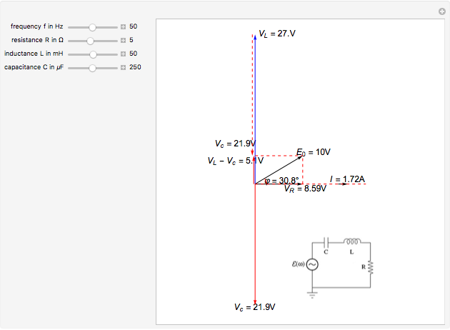
Phasor Diagram for Series RLC Circuits - Wolfram ... This Demonstration shows a phasor diagram in an AC series RLC circuit. The circuit consists of a resistor with resistance , an inductor with inductance , and a capacitor with capacitance . The current in an RLC series circuit is determined by the differential equation [more] Contributed by: Anping Zeng (July 2011)

RLC Series circuit, phasor diagram with solved problem
phasor diagram of rlc circuit - Wiring Diagram and Schematics what is rlc series circuit phasor diagram impedance triangle globe electrical4u analysis a connection of l c and b its scientific for circuits wolfram demonstrations project ac containing resistor an inductor capacitor in formula solved example problems alternating cur chapter 33 continued diagrams definition the phasors chegg com are parallel …
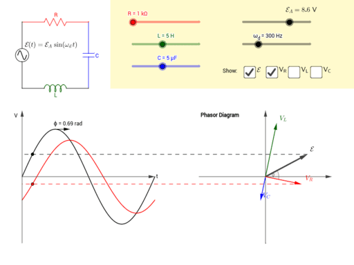
Driven RLC Circuit Using Phasors – GeoGebra
Phasor Diagram of Parallel RLC Circuit - YouTube Network Theory: Phasor Diagram of Parallel RLC Circuit Topics discussed:1) Phasor diagram of Parallel RLC circuit.2) Current triangle of Parallel RLC circuit...
What is RLC Series Circuit? - Phasor Diagram & Impedance ...
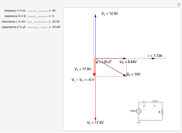
Chapter 12.3 - Phasor Diagram of Series RLC Circuit ... The phasor diagram is shown in Figure 12.4 ( c ). Example 12.6. A series RLC circuit consists of a resistance R = 10Ω, inductance L = 0.2H, and capacitance C = 0.2μF. Calculate the frequency of resonance. A10 volts sinusoidal voltage at the frequency of resonance is applied across the circuit. Draw the phasor diagram showing the value of
Phasor Diagram for Series RLC Circuits - Wolfram ...
RC | RLC | RL Series Circuits - your electrical guide In an RLC series circuit a pure resistance (R), pure inductance (L) and a pure capacitor (C) are connected in series. To draw the phasor diagram of RLC series circuit, the current I (RMS value) is taken as the reference vector. The voltages across three components are represented in the phasor diagram by three phasors V R, V L and V C respectively. The voltage drop V L is in phase opposition ...

Phasor diagram - LCR circuit - For Xc greater than XL / Capacitive reactance greater than inductive
Solved (Figure 1) shows the phasor diagram for an RLC ... (Figure 1) shows the phasor diagram for an RLC circuit. Figure 1 of 1 VLE VCP VRP Complete the diagram by adjusting the applied voltage phasor. Adjust the end point of the applied voltage phasor to complete the phasor diagram. The orientation and length of the phasors will be graded.
RLC Series circuit, phasor diagram with solved problem
RLC Parallel circuit analysis with solved problem RLC Parallel circuit is the circuit in which all the components are connected in parallel across the alternating current source. In contrast to the RLC series circuit, the voltage drop across each component is common and that's why it is treated as a reference for phasor diagrams.
AC circuit containing a resistor, an inductor and a capacitor ...
Series Resonance in a Series RLC Resonant Circuit We recall from the previous tutorial about series RLC circuits that the voltage across a series combination is the phasor sum of V R, V L and V C. Then if at resonance the two reactances are equal and cancelling, the two voltages representing V L and V C must also be opposite and equal in value thereby cancelling each other out because with ...
What is RLC Series Circuit? - Phasor Diagram & Impedance ...
What is RLC Series Circuit? - Phasor Diagram & Impedance PHASOR DIAGRAM OF RLC SERIES CIRCUIT As seen from the phasor diagram that Vₗ and Vc are 180 degree out of phase, they are direct opposite to each other. So effective voltage will be (Vₗ-Vc). Applied voltage is phasor sum of the voltage across resistance & effective voltage. V = √ { (Vr)² + (Vₗ -Vc)²} V = √ { (I*R)² + (I*Xₗ - I*Xc)²}
Phasor Diagram of RL, RC and RLC Circuits (with Examples)
Series RLC Circuit Impedance Calculator • Electrical, RF ... The phasor diagram shows the V T voltage of the ideal sine voltage source. The voltage drop on the resistor V T is shown on the horizontal axis in phase with the current that flows through the circuit. The inductance voltage vector V L lags the current in the inductance vector by 90°, therefore it is drawn at +90°.
Phasor Diagram for Series RLC Circuits - Wolfram ...
RLC Series Circuit - Georgia State University RLC Series Circuit. The RLC series circuit is a very important example of a resonant circuit.It has a minimum of impedance Z=R at the resonant frequency, and the phase angle is equal to zero at resonance.. One way to visualize the behavior of the RLC series circuit is with the phasor diagram shown in the illustration above. The phasor diagram shown is at a frequency where the inductive ...

RLC Series circuit, phasor diagram with solved problem
Series RLC Circuit (Circuit & Phasor Diagram) | Electrical4U

Phasor - Wikipedia
SOLVED:Figure 24-38 shows the phasor diagram for an R L C ...
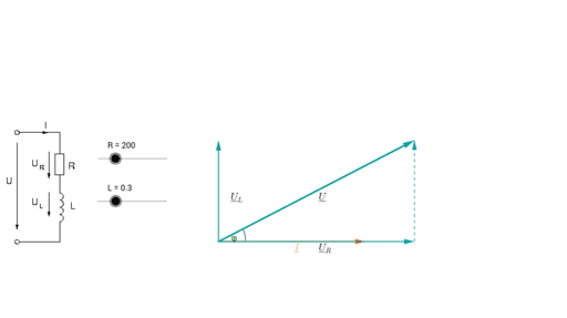
Phasor Diagram - RL Series Circuit – GeoGebra
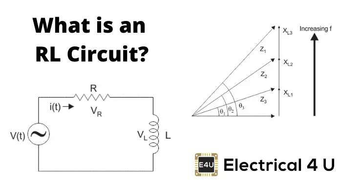
RL Series Circuit Analysis (Phasor Diagram, Examples ...

Phase angle of the electric current, circulating in the RLC ...

What are Series RLC Circuit and Parallel RLC Circuit?
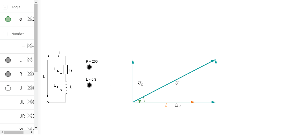
Phasor Diagram - RL Series Circuit – GeoGebra
What is Parallel Resonance? Effect of Frequency & Phasor ...

In the figure, which of the phasor diagrams represents `RLC` circuit driven at resonance?
LCR Series Circuits
Series RLC Circuit | Analysis | Phasor Diagram | Impedance ...
RLC Circuit Analysis (Series And Parallel) – Clearly ...
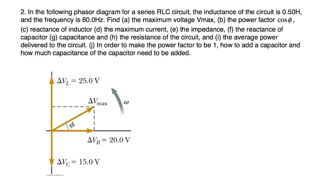
SOLVED:2. In the following phasor diagram for a series RLC ...

Parallel RLC Circuit — Collection of Solved Problems

Current and Voltages Computations in Series RLC circuit

inductor - Explaination on phasor diagram for RL circuit ...
We shall examine three special cases of driven circuits
RLC Series Circuits with AC – University Physics Volume 2
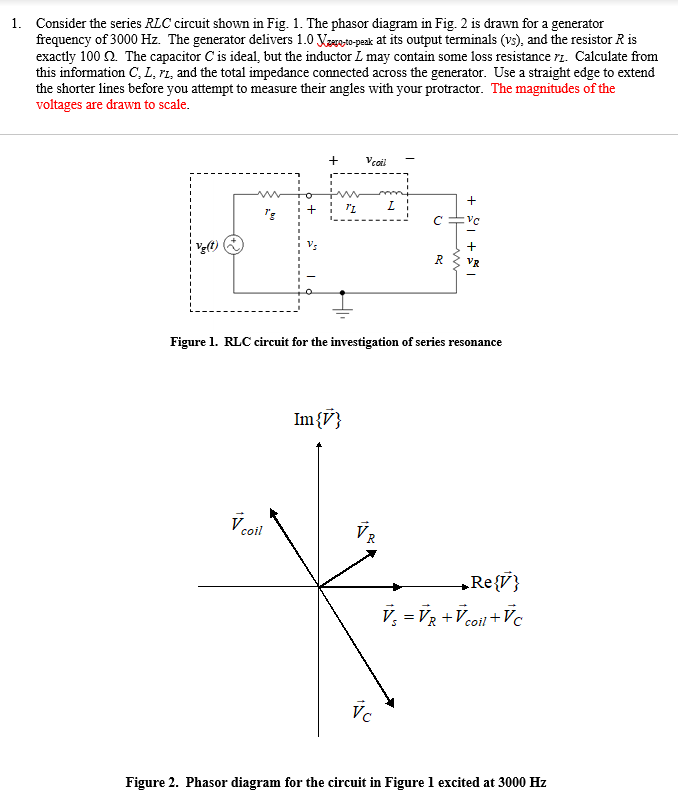
1. Consider the series RLC circuit shown in Fig. 1. | Chegg.com

Parallel RLC Circuit and RLC Parallel Circuit Analysis

Series RLC Circuit Impedance Calculator • Electrical, RF and ...

Phasor Diagram and Phasor Algebra used in AC Circuits
Parallel RLC Circuit — Collection of Solved Problems

Additional Problems(80)Figure \"a\" shows a parallel RLC ...

Parallel LC Circuit Impedance Calculator • Electrical, RF and ...

a) Series connection of L C circuit and (b) its phasor ...
0 Response to "43 rlc circuit phasor diagram"
Post a Comment