42 isothermal transformation diagram for an iron–carbon alloy
with iron-copper alloys was determined at 950 . 0 , 1000 0 , and 1050 0 . c. The results of gas carburization and graphite solubility . experi~ents . at 950°C were used in constructing an isothermal section of the iron-rich end of the iron-copper-carbon phase diagram, on which are superimposed carbon isoactivity lines. Graphite solubil April 7th, 2019 - Iron Carbon Phase Diagram Its defined as A map of the temperature at which different phase changes occur on very slow heating and cooling in relation to Carbon content is Isothermal and continuous cooling transformation diagrams for plain carbon and alloy steels Iron Carbon diagram shows Isothermal transformation diagram Wikipedia
A sensitive magnetic permeability method for rapid determination of isothermal transformation diagrams in steel and iron base alloys is described. The method consists of quenching the sample from an austenitizing temperature to a subcritical temperature in an isothermal bath, and holding it within the magnetic field of an inductor coil.

Isothermal transformation diagram for an iron–carbon alloy
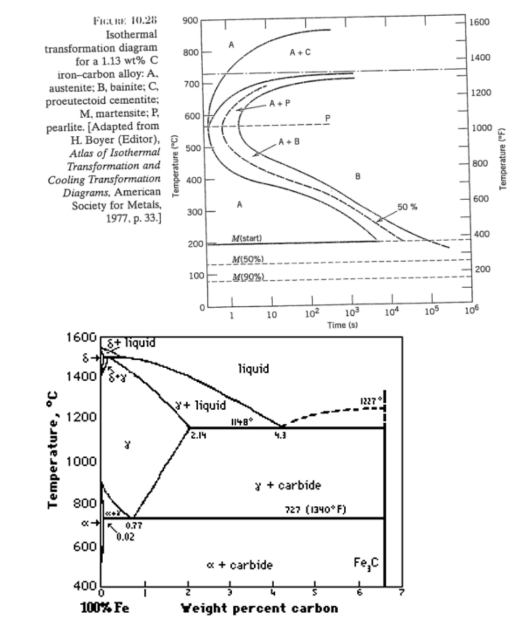
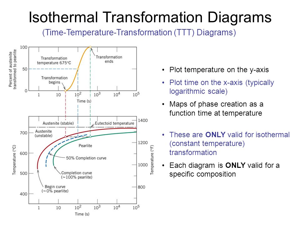
1019 using the isothermal transformation diagram for an iron carbon alloy of eutectoid composition. The thickness of the ferrite and cementite layers in pearlite is 81. Figure 1022 specify the nature of the final microstructure in terms of microconstituents present and. 6 Make A Copy Of The Isothermal Transformation Diagram For An Iron Isothermal Transformation and Cooling Transformation Diagrams, 1977. Reproduced by permission of ASM International, Materials Park, OH.] Generation of Isothermal Transformation Diagrams • The Fe-Fe3C system, for C0= 0.76 wt% C • A transformation temperature of 675 ºC. 100 50 0 1102 104 T = 675°C y, % transformed time (s) 400 500 600 700 ... Isothermal transformation diagram for an iron-carbon alloy of eutectoid composition, including austenite-to-pearlite (A-P) and austenite-to-bainite (A-B) transformations. "Nose" of T-T-T curve between pearlite and bainite transformations means bainite cannot be
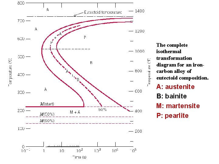
Isothermal transformation diagram for an iron–carbon alloy. Time-Temperature-Transformation (TTT) diagram or S-curve refers to only one steel of a particular composition at a time, which applies to all carbon steels.This diagram is also called as C-curve isothermal (decomposition of austenite) diagram and Bain's curve.The effect of time-temperature on the microstructure changes of steel can be shown by the TTT diagram. The complete isothermal transformation diagram for an iron carbon alloy of eutectoid composition. In their simplest form steels are alloys of iron fe and carbon c. Of materials science and engineering 2. 1019 using the isothermal transformation diagram for an iron carbon alloy of eutectoid composition. Atlas of Isothermal Transformation Diagrams of B.S. En Steels-British Iron and Steel Research Association 1956 Atlas of Isothermal Transformation Diagrams- 1953 Atlas of Isothermal Transformation Diagrams- 1953 Atlas of Isothermal Transformation Diagrams-United States Steel Corporation, Pittsburgh, Pa 1951 1953 Supplement to Atlas of Isothermal Using the isothermal transformation diagram for an iron-carbon alloy of eutectoid composition. The nature of the final microstructure of the specimen which is subjected to various heat treatment processes can be found out by use of figure 1022 complete isothermal transformation diagram for an iron carbon alloy of eutectoid composition.
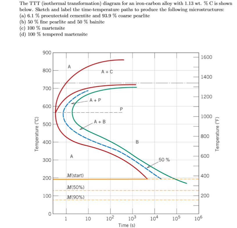
Make a copy of the isothermal transformation diagram for an iron-carbon alloy. Make a copy of the isothermal transformation. diagram for an iron-carbon alloy of eutectoid. composition (Figure 10.22) and then sketch and. label time-temperature paths on this diagram to. produce the following microstructures: (a) 100% coarse pearlite. Knowing these limitations, the use of isothermal Time Temperature Transformation, and Continuous Cooling Transformation diagrams can be a great aid in planning and controlling the heat treatment of steel. The TTT curves portray the fundamental transformation characteristics of the alloy. Isothermal transformation diagrams university of portland isothermal transformation diagrams 10 18 using the isothermal transformation diagram for an ironcarbon alloy of eutectoid position download free and get a copy in your email. 1019 using the isothermal transformation diagram for an iron carbon alloy of eutectoid composition figure 1022 specify the nature of the final microstructure in ... FREE Answer to Make a copy of the isothermal transformation diagram for an iron–carbon alloy of eutectoid composition provided...1 answer · 0 votes: In this solution some basic concepts of Metallurgy are used. For more information, refer to any standard textbook or drop a comment below. Please give ...
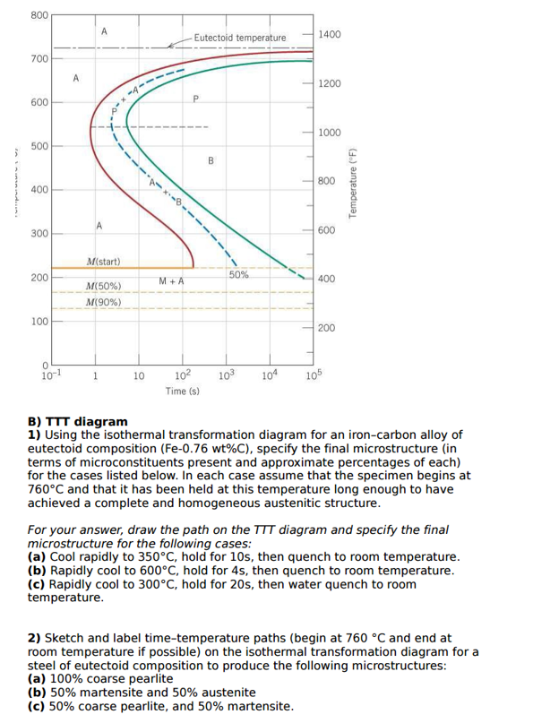
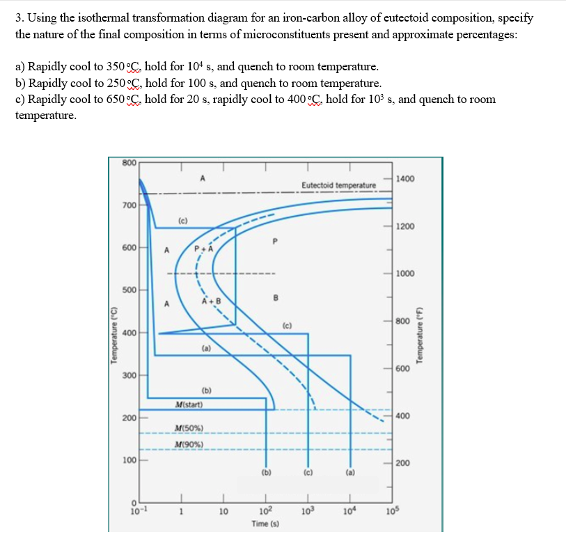
Transcribed image text: 1. The isothermal transformation diagram for an iron-carbon alloy of eutectoid composition is shown right. Specify the nature of the final microstructure (in terms of micro-constituents present and approximate percentages of each) of a specimen that has been subjected to the following time-temperature treatment. a). cool rapidly to room temperature. b). cool rapidly to ... Using the isothermal transformation diagram for an iron-carbon alloy of eutectoid composition (Figure 10.22), specify the nature of the final microstructure (in terms of micro constituents present and approximate percentages of each) of a small specimen that has been subjected to the following time-temperature treatments. Step 1. 1 of 3. We have to use the isothermal transformation diagram for an iron-carbon alloy of eutectoid composition form Figure 10.22 in order to specify the nature of the final microstructure of a small specimen: T 1 = 760 C T_1=760\text { C} T 1 = 760 C. A) \textbf { A)} A) Cool rapidly to. T = 350 C T=350\text { C} T = 350 C. Using the isothermal transformation diagram. Solution we are called upon to consider the isothermal transformation of an iron carbon alloy of eutectoid composition. Ttt diagram stands for time temperature transformation diagram. A from figure 1022 a horizontal line at 550 c intersects the 50 and reaction completion curves at about 25 and 6 ...
Physical Metallurgy Of Ferrous Alloys Book Chapter Iopscience
Iron Carbon Ttt Diagram. TTT diagram is a plot of temperature versus the logarithm of time for a steel alloy of The complete isothermal transformation diagram for an iron-carbon alloy. Imagine, for example, some pure iron that was kept at a temperature of oC ( .. Here is the "official" isothermal TTT diagram for eutectoid carbon steel.

Using The Isothermal Transformation Diagram For An Iron Carbon Alloy Of Eutectoid Composition Figure 11 23 Specify The Nature Of The Final Microstructure In Terms Of Microconstituents Present And Study Com
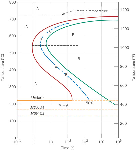
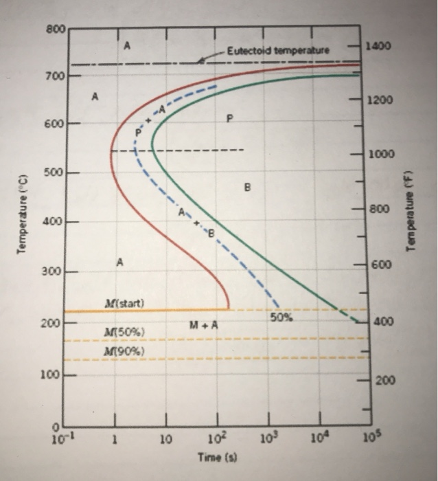
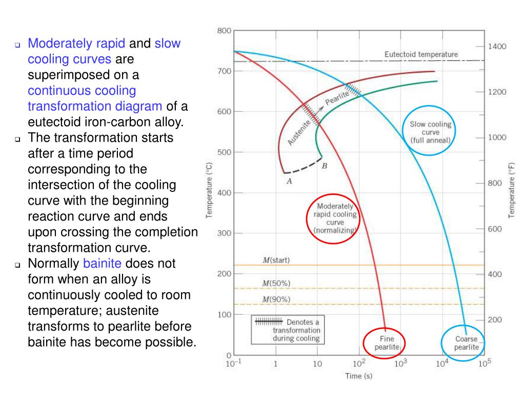
Isothermal transformation diagram for a iron-carbon alloy of eutectoid composition. The letters indicate specific phases: austenite (A), pearlite (P), bainite (B), and martensite (M). The solid blue lines indicate two cooling paths resulting in 100% pearlite (top) and 100% bainite (bottom). Modified from image from aarontan.org
Module 5 Metallic Materials Http Www Tntech Edumecourseszhangmodule205m
7.3. Using the isothermal transformation diagram for an iron-carbon alloy of eutectoid composition, specify the nature of the final microstructure of a small specimen that has been subjected to the following time-temperature treatments. In each case assume that the specimen begins at 760°C and that it has been held at this temperature long ...
Metals Free Full Text Effects Of Chemical Composition And Austenite Deformation On The Onset Of Ferrite Formation For Arbitrary Cooling Paths Html
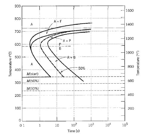
Below is shown an isothermal transformation diagram for a 0.45 wt% C iron-carbon alloy, with time-temperature paths that will produce (a) 42% proeutectoid ...27 pages
Solved On The Basis Of Accompanying Isothermal Chegg Com
Fig.4: Time temperature transformation (schematic) diagram for plain carbon eutectoid steel t 1 t 2 t 3 t 4 t 5 M F, Martensite finish temperature M 50, 50% Martensite M S, Martensite start temperature Metastable austenite +martensite Martensite e 0 100 e Log time Hardness A e1 T 2 T 1 50% T T 2 1 Pearlite Fine pearlite Upper bainite Lower bainite

Cct Diagram Steel Material Science Mechanical Engineering Diagram
Using the isothermal transformation diagram for an iron-carbon alloy of eutectoid composition (Figure), specify the nature of the final microstructure (in terms of micro constituents present and approximate percentages of each) of a small specimen that has been subjected to the following time-temperature treatments.
Answered Fulre 10 28 Isothermal 900 1600 Bartleby
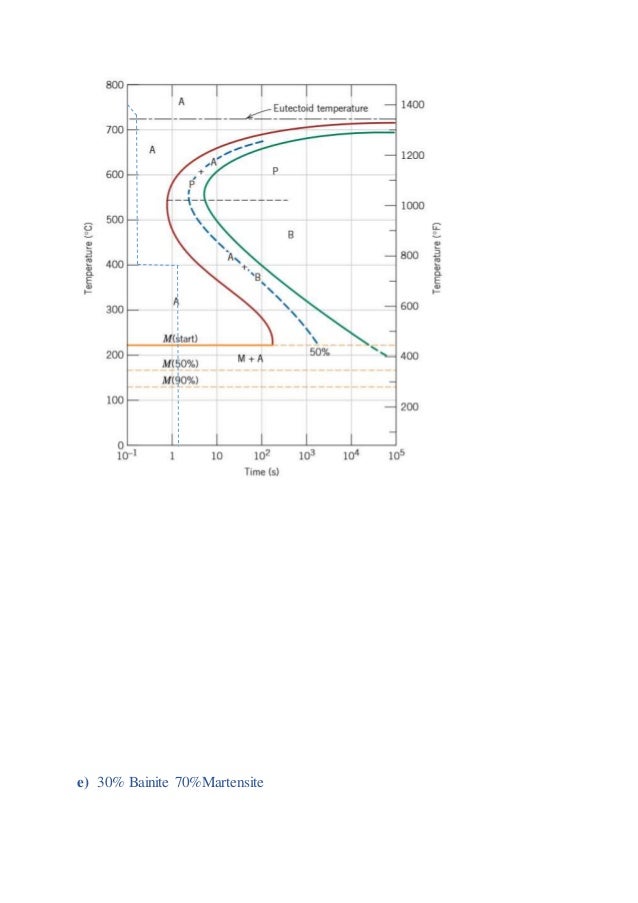
10.18 Below is shown an isothermal transformation diagram for a 0.45 wt% C iron-carbon alloy, with time-temperature paths that will produce (a) 42% proeutectoid ferrite and 58% coarse pearlite; (b) 50% fine pearlite and 50% bainite; (c) 100% martensite; and (d) 50% martensite and 50% austenite.
Isothermal Transformation Diagrams Ppt Video Online Download
Iron carbon phase diagram a review see callister chapter 9. The complete isothermal transformation diagram for an iron carbon alloy of eutectoid composition. Assignment 2 Solutions In their simplest form steels are alloys of iron fe and carbon c. Using the isothermal transformation diagram for an ironcarbon alloy of eutectoid composition. 1018 ...

Using The Isothermal Transformation Diagram For An Iron Carbon Alloy Of Eutectoid Composition Specify The Nature Of The Final Microstructure In Terms Of Microconstituents Present And Approximate Perc Study Com
Using the isothermal Transformation Diagram for An Iron-carbon Alloy Of Eutectoid Composition. solved 10 19 using the isothermal transformation diagram 10 19 using the isothermal transformation diagram for an iron carbon alloy of eutectoid position figure 10 22 specify the nature of the final microstructure in terms of microconstituents present and approximate percentages of each of a small ...
Nanopdf Com
Question: Using the isothermal transformation diagram for an iron-carbon alloy of eutectoid composition (see Figure 10.22 below), specify the nature of the ...
Xdocs Tips
10.18 Using the isothermal transformation diagram for an iron-carbon alloy of eutectoid composition (Figure 10.22), specify the nature of the final microstructure (in terms of microconstituents present and approximate percentages of each) of a small specimen that has been subjected to the following time-temperature treatments. In
Metals Free Full Text Mathematical Modelling Of Isothermal Decomposition Of Austenite In Steel Html
The isothermal transformation diagrams are a graph or pictorial representation of the temperature changes with respect to time in the particular alloy ...
Solved The Ttt Isothermal Transformation Diagram For An Chegg Com
Below is shown the isothermal transformation diagram for a eutectoid iron-carbon alloy, with time- temperature paths that will yield (a) 100% fine pearlite; (b) ...12 pages
Solved Using The Isothermal Transformation Diagram For An Chegg Com
Using the isothermal transformation diagram for an iron-carbon alloy of eutectoid composition, specify the nature of the final microstructure (in terms of microconstituents present and approximate ...
Answered Using The Isothermal Transformation Bartleby
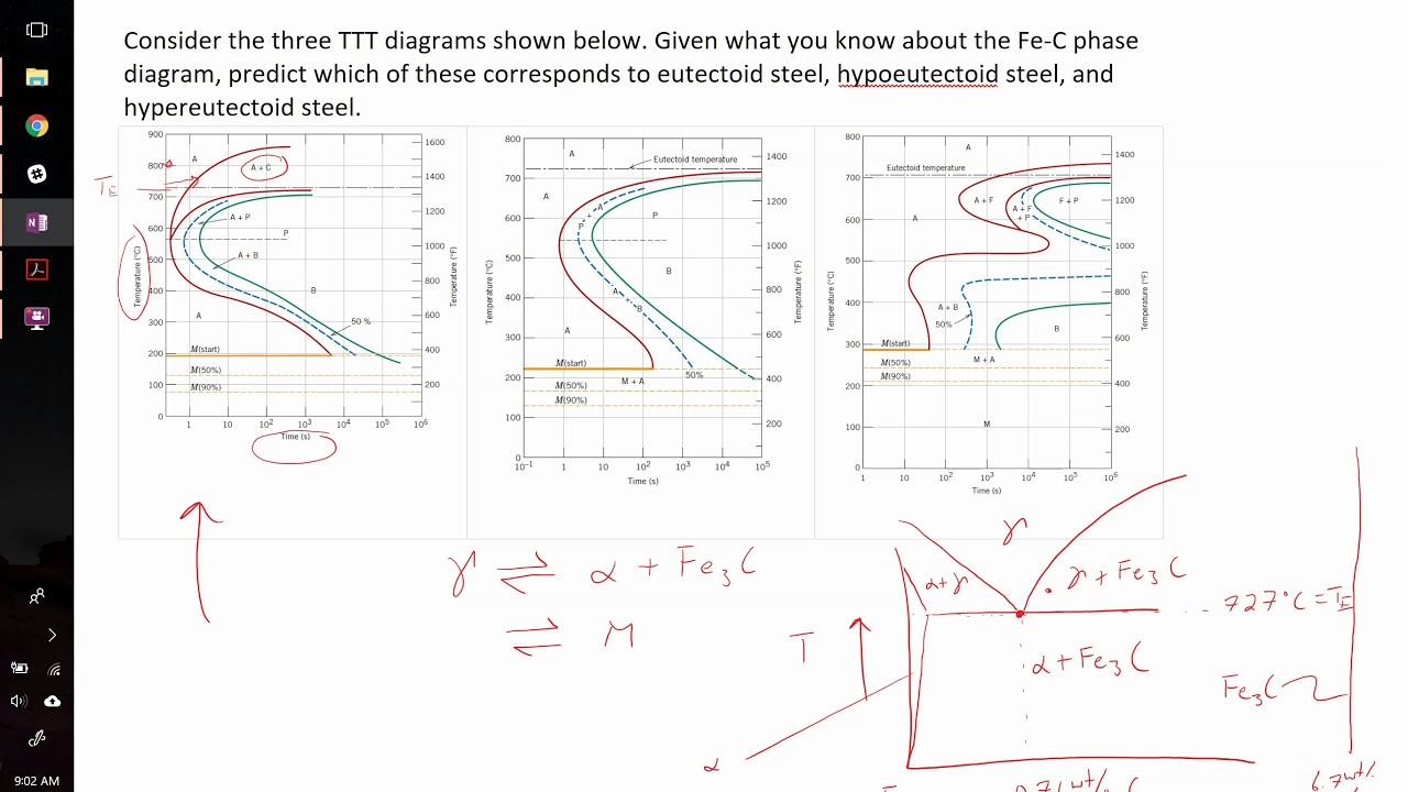
TTT diagram is a plot of temperature versus the logarithm of time for a steel alloy of The complete isothermal transformation diagram for an iron-carbon alloy.C metastable equilibrium diagram and TTT diagrams for plain carbon hypoeutectoid, eutectoid and hypereutectoid steels M S (a) Fe-Fe 3 C metastable phase diagram (b) TTT diagram for ...
Zackrauen Com
Using the isothermal transformation diagram for an ironcarbon alloy of eutectoid composition figure 1022 specify the nature of the final microstructure in terms of microconstituents present and approximate percentages of each of a small specimen that has been subjected to the following timetemperature treatments. 1018 using the isothermal transformation diagram for an ironcarbon alloy of ...
Zackrauen Com
Isothermal transformation diagram for an iron-carbon alloy of eutectoid composition, including austenite-to-pearlite (A-P) and austenite-to-bainite (A-B) transformations. "Nose" of T-T-T curve between pearlite and bainite transformations means bainite cannot be
Site Iugaza Edu Ps
Isothermal Transformation and Cooling Transformation Diagrams, 1977. Reproduced by permission of ASM International, Materials Park, OH.] Generation of Isothermal Transformation Diagrams • The Fe-Fe3C system, for C0= 0.76 wt% C • A transformation temperature of 675 ºC. 100 50 0 1102 104 T = 675°C y, % transformed time (s) 400 500 600 700 ...
Che Uri Edu
1019 using the isothermal transformation diagram for an iron carbon alloy of eutectoid composition. The thickness of the ferrite and cementite layers in pearlite is 81. Figure 1022 specify the nature of the final microstructure in terms of microconstituents present and. 6 Make A Copy Of The Isothermal Transformation Diagram For An Iron

Question 4 10 Points A Using The Isothermal Transformation Diagram For Iron Carbon Alloy Of Eutectoid Homeworklib
Faculty Up Edu

Isothermal Transformation Diagram Wikipedia

Isothermal Transformation Diagram Wikipedia
Solved Using The Isothermal Transformation Diagram For An Chegg Com
Pdfcoffee Com
Prosiding Bkstm Org

Isothermal Transformation Behavior And Microstructural Evolution Of Micro Alloyed Steel Intechopen

Isothermal Transformation Kinetics Microstructure And Mechanical Properties Of A Carbide Free Bainitic Steel Sciencedirect
Solved 10 20 Make A Copy Of The Isothermal Transformation Chegg Com

Ttt Diagram Of Steel In Material Science Materials Today
1
Xdocs Tips

Below Is Shown The Isothermal Transformation Diagram For A 0 45 Wt C Iron Carbon Alloy List The Microconstituent S Present For The Heat Treatment Labeled On This Diagram It Is Not Necessary To State
Pdfcoffee Com
Ttt Diagrams For Different Carbon Concentrations Example Problem Youtube

Make A Copy Of The Isothermal Transformation Diagram For A 1 Quizlet
Ttt Phase Transformation Physics Forums

Below Is Shown The Isothermal Transformation Diagram For A 0 45 Wt C Iron Carbon Alloy List The Microconstituent S Present For The Heat Treatment Labeled A On This Diagram It Is Not Necessary To

Oneclass Using The Supplied Isothermal Transformation Diagram For An Irona Carbon Alloy Of Eutectoi

Using The Isothermal Transformation Diagram For An Iron Carbon Alloy Of Course Hero
Ppt Chapter 11 Phase Transformations Powerpoint Presentation Free Download Id 6600469
Assignment 2 Solutions
0 Response to "42 isothermal transformation diagram for an iron–carbon alloy"
Post a Comment