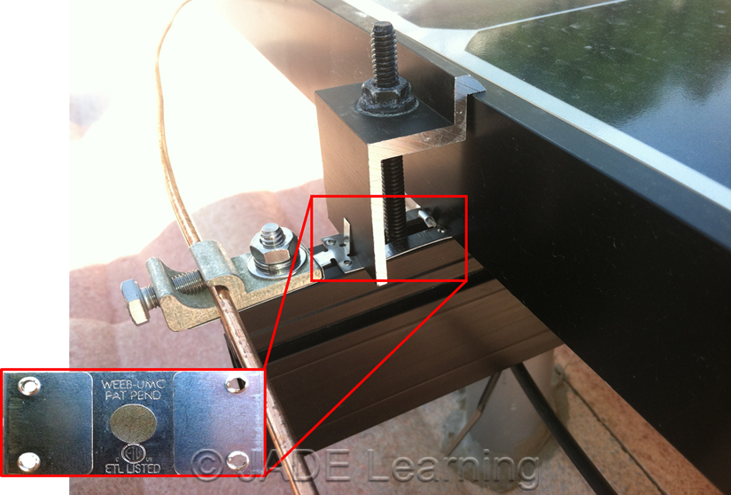
44 pv system grounding diagram
(1) Grounding of solar photovoltaic system output, ac grounding For parallel connection of solar photovoltaic systems, depending on the point of connection, the utility disconnecting means may be required to be an approved service box, as per Diagrams B1 and B3. grounding electrode system or is functionally grounded through an overcurrent protection device (OCPD) to a grounding electrode system. Grounding of exposed metal surfaces likely to become energized, also known as equipment grounding, is a requirement for all electrical systems governed by the NEC.
Figure 2 shows a similar vector diagram on a solidly grounded system with the same single-line-to-ground fault applied on phase A. The transformer neutral is tied to ground solidly so that the neutral potential cannot change with the fault applied. ... Effective Grounding for PV Plants EFFECTIVE ). /

Pv system grounding diagram
Block diagram of PV system ... Electrical diagram showing PV array configuration, wiring system, ... 690.42 Point of System Grounding Connection—one.168 pages The energy production from solar photovoltaic system has gained attention worldwide as it a clean and renewable source of energy. The power output of solar ... connected PV systems. PV System Equipment Ground NEC 690.45(A) requires that equipment grounding conductors for PV source and output circuits be sized in accordance with NEC table 250.122, which allows for a smaller gauge ground wire, such as a # 10 or #12 AWG, to be used in this
Pv system grounding diagram. Grounding Electrode System and Grounding Electrode Conductor Part III zNEC 250.50 (Grounding Electrode System) 250.52 Electrodes Water Pipe if 10 ft. or more of metal water pipe is in contact with the earth. Metal Frame of the Building or Structure where the following methods are used to make an earth connection: (1,2,3,4) used in the MV ac collection system of a PV power plant. This type of transformer is commonplace. It is used wher-ever 3-phase building loads are served by an underground MV distribution system. Transformer location often varies based on system capac-ity. In commercial-scale PV systems that are interconnected grounded in some way,” sayeth ye. National Electrical Code (NEC). This. Code Corner will begin with the code requirements for a PV system from the.6 pages There are three main reasons for grounding in an off-grid power system: safety, v oltage transients, and t h e sheer fact that they are required for some loads. But before we address each of these, it’s important to understand the actual definition of ‘ground’. There are two types of ground: chassis (or mechanical) and electrical.
The electrical insulation from the PV system to ground is defective or insufficient. ... 559183116. Schematic diagram of the measurement ... 1 Jun 2020 — First, earth is NOT a good conductor. Consequently in the diagram you show you can not assume the house ground and utility ground are tied ... 2 Dec 2020 — Diagram below shows USE-2 or PV Wire is acceptable for Functional Grounded PV systems (includes isolated and non-isolated PV system inverter ...162 pages Class II. Modules rated under this class should be used in systems operating at a voltage above 50 VDC or power above 240 W, where general contact access is anticipated. A photovoltaic system composed of UL1703 certified modules mounted on a UL2703 certified mounting system should be evaluated
6 Photovoltaic System Grounding Introduction Proper grounding of a photovoltaic (PV) power system is critical to ensuring the safety of the public during the installation’s decades-long life. Although all components of a PV system may not be fully functional for this period of time, the basic PV module can For simplicity, the example online diagrams below exclude system components not relevant to grounding requirements; these drawings are not intended to be used as example onelines for system design. Example 1 – Separate Zig‐Zag Grounding Transformer A PV facility with 1 MVA inverter total AC nameplate is interconnected to a 13.8kV feeder connected PV systems. PV System Equipment Ground NEC 690.45(A) requires that equipment grounding conductors for PV source and output circuits be sized in accordance with NEC table 250.122, which allows for a smaller gauge ground wire, such as a # 10 or #12 AWG, to be used in this The energy production from solar photovoltaic system has gained attention worldwide as it a clean and renewable source of energy. The power output of solar ...
Block diagram of PV system ... Electrical diagram showing PV array configuration, wiring system, ... 690.42 Point of System Grounding Connection—one.168 pages


0 Response to "44 pv system grounding diagram"
Post a Comment