42 curt brake controller wiring diagram
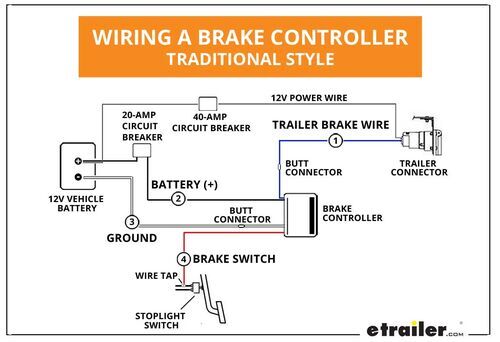
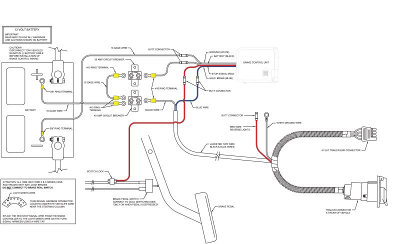
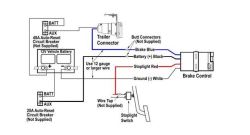
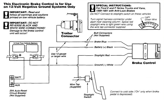
Run a 10 gauge blue wire from the tow vehicle's trailer plug 'brake' terminal to the brake control. Using a 10/12 butt connector, connect this wire to the brake control's blue wire. Connect the brake control's red wire to the cold side of the tow vehicle's stoplight switch using a wire tap.
CURT part# 51500 - brake controller wiring kit. Important Information. Read and follow installation and setup instructions carefully. Failure to do so could.20 pages
curt brake controller wiring diagram - curt brake controller wiring diagram Download 7 Way Trailer Plug Wiring Diagram Gmc Lovely Brake. File Type: JPG. Source: magnusrosen.net. Assortment of curt brake controller wiring diagram. Click on the image to enlarge, and then save it to your computer by right clicking on the image.

Curt brake controller wiring diagram
curt brake controller wiring diagram – What’s Wiring Diagram? A wiring diagram is a kind of schematic which uses abstract photographic signs to reveal all the affiliations of elements in a system. Wiring layouts are made up of 2 things: signs that stand for the elements in the circuit, and lines that stand for the connections between them.
CURT part# 51500 - brake control wiring kit. Important Information ... in the outside row of seven wires (see the box shown in wiring the diagram). Splice.20 pages
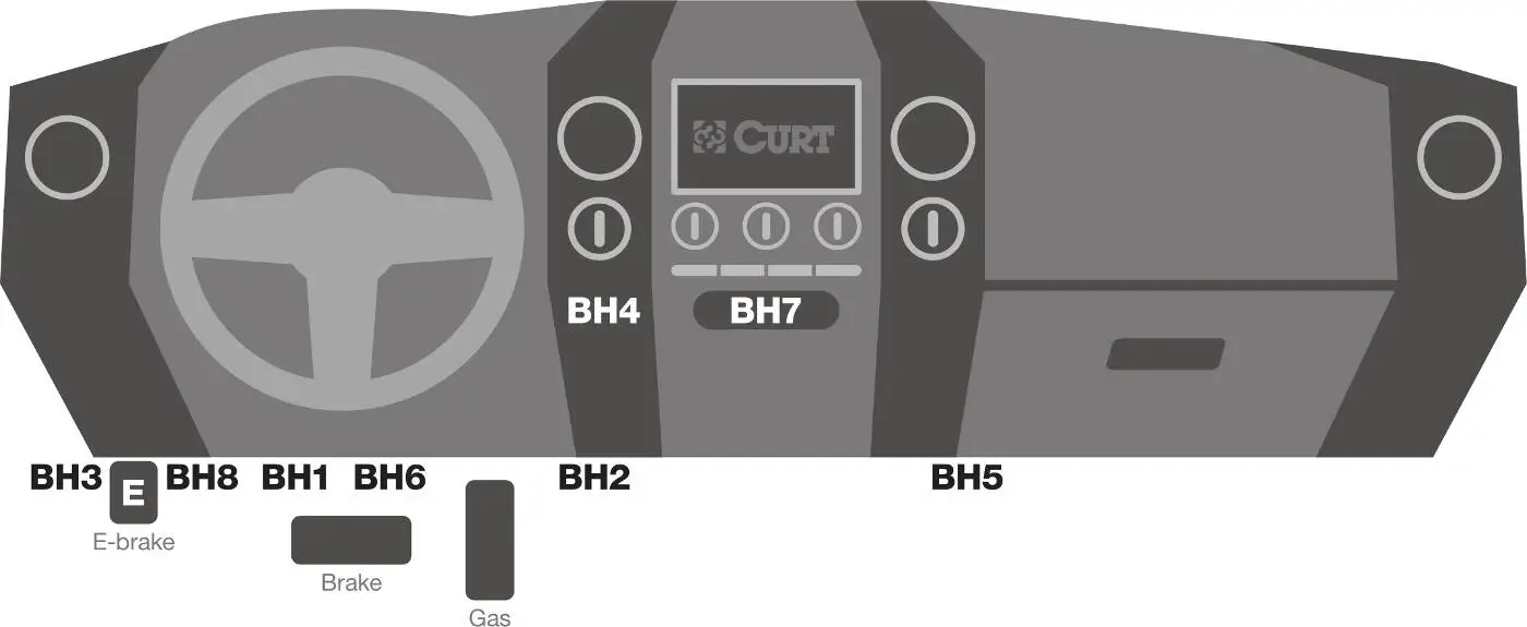
- Brake Control connection harness supplied with the tow vehicle (if equipped) - CURT Quick Plug - custom connector for specific vehicles. See catalog for availability - CURT part number 51515 male Quick Plug with pigtails - CURT part number 51500 Brake Control Wiring Kit Important Features - Digital display provides detailed brake force output.
Curt brake controller wiring diagram.
International 4400 brake light switch location
Curt Trailer Brake Controller Wiring Diagram – People today comprehend that trailer is a car comprised of quite complicated mechanisms. This car is designed not only to travel one place to another but also to take heavy loads. This article will be talking curt trailer brake controller wiring diagram.
Variety of curt brake controller wiring diagram. A wiring diagram is a simplified standard photographic depiction of an electrical circuit. It reveals the components of the circuit as streamlined shapes, and the power and also signal connections between the devices.
Check the switch’s wiring diagram and find the single wire that establishes a connection between the brake light and turn signal switches. 2010 CHEVROLET MALIBU - SERVICE BRAKES, HYDRAULIC:SWITCHES:BRAKE LIGHT Problem: General Motors LLC (GM) is recalling certain model year 2004-2012 Chevrolet Malibu vehicles manufactured May 16, 2003, through October …
23.10.2019 · The Curt Echo is perhaps the easiest brake controller on the market to install. Simply plug the unit in between your 7-way trailer connection, download the mobile app to your smartphone, and pair your devices using Bluetooth. No crimping, splicing, or other alterations necessary, provided you already have a vehicle with a 7-way plug (if you don't, you can
Find the fuse number using the diagram on the back of the cover. 2001 Chevy Silverado Power Window Wiring Diagram Chevy. This can cause damage to the electrical system and fire. No brake lights 2005 silverado. They use an app 1 3/4 x 3/4 cutout. The fuse for the dash lights on a 2002 Chevy Tahoe is in the fuse box in the interior of the vehicle. 1999-2013 Silverado & Sierra …
DOWNLOAD. Wiring Diagram Images Detail: Name: curt brake controller wiring diagram – Trailer Brake Controller Wiring Diagram Inspirational Wiring Diagram Trailer Brakes Refrence Tekonsharodigy2 Wiring. File Type: JPG. Source: originalstylophone.com. Size: 337.93 KB. Dimension: 1920 x 1299.
curt discovery brake controller wiring diagram - Just What's Wiring Diagram? A wiring diagram is a sort of schematic which uses abstract photographic signs to show all the affiliations of parts in a system.
Ford Super Duty Trailer Brake Wiring Snowplow Forums. Brake controller installation starting trailer control wiring diagram electric troubleshooting install ih8mud forum tekonsha powertrac official subaru controllers explained electronic 12v operation what is a 90885 prodigy p2 installing controls on car electrical wires cable ford super duty reese brakeman iv connection toyota fh10 for 03 07 ...
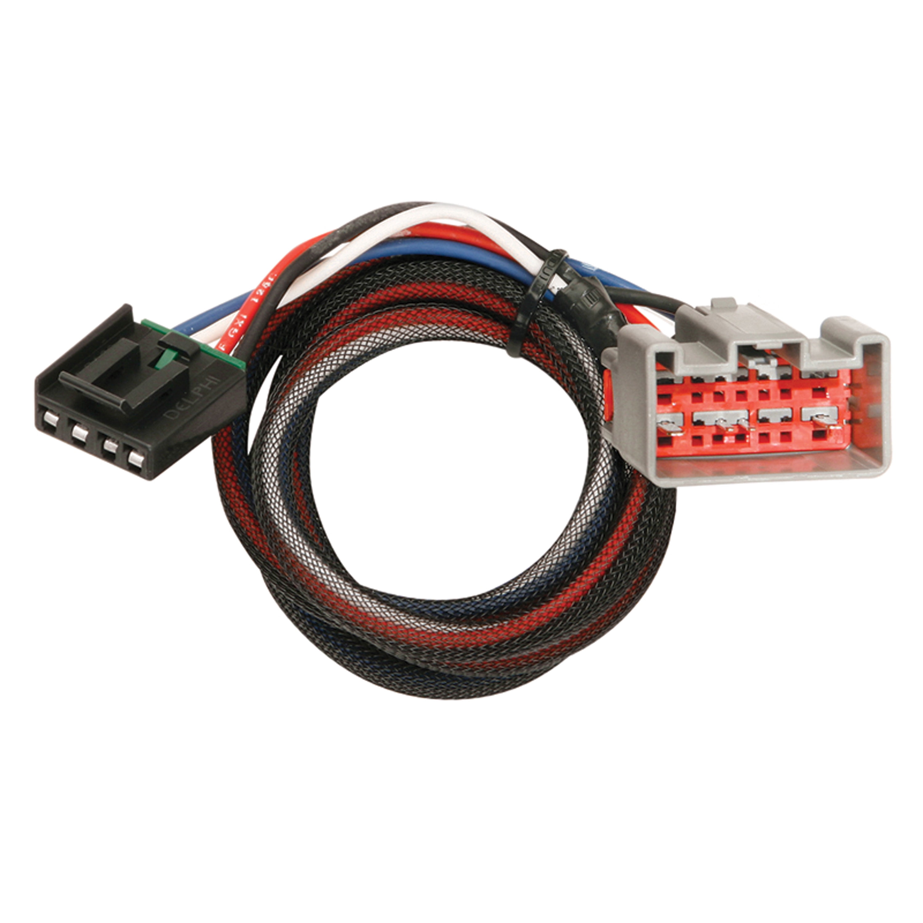
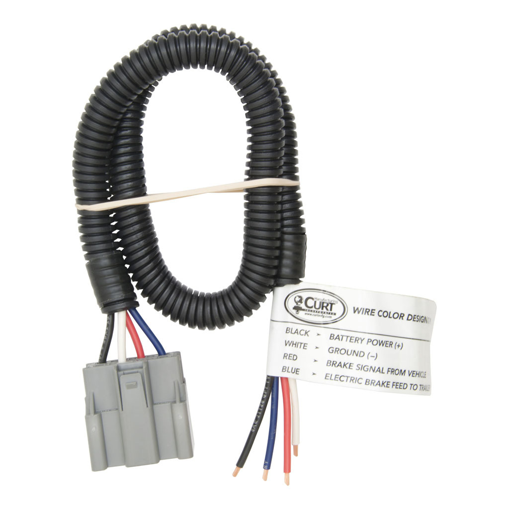
All CURT trailer brake controller wiring is equipped with quick plugs for the easiest possible install. Your account has been temporarily locked, so no orders can be placed at this time. Please contact our accounts receivable department at 877-287-8634 or email [email protected] Shop All Lippert Brands ...
Name: curt discovery brake controller wiring diagram - Curt Discovery Brake Control Wiring Diagram 0; File Type: JPG; Source: natebird.me; Size: 419.53 KB; Dimension: 1920 x 1080; A Beginner's Guide to Circuit Diagrams. A first look at the circuit diagram might be confusing, in case search for a subway map, look for schematics.
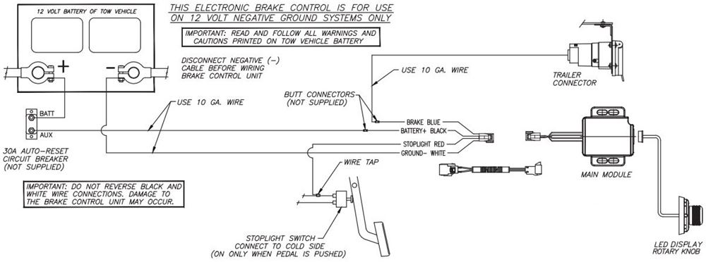
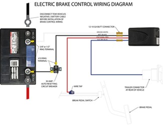
we suggest the CURT brake control wiring kit, part# 51500. PAGE 10 WIRING DIAGRAM IMPORTANT: Make sure that both positive and ground connections are made directly to the tow vehicle's battery. Connecting to existing wiring or chassis ground, other than the
How to install your brake control
Curt Brake Controller Wiring Diagram. Category : Wiring Diagram; Post Date : April 21, 2021; Filled in: Wiring Diagram Curt Brake Controller Wiring Diagram 9 out of 10 based on 90 ratings. 10 user reviews. schema de Curt Brake Controller Wiring Diagram. Wiring Diagram Tekonsha Voyager Brake Controller 39510.
Advance auto brake controller for sale > off-67%
VENTURER VENTURER BRAKE CONTROL INSTALLATION AND USER GUIDE. PAGE 2 we suggest the CURT brake control wiring kit, part# PAGE 10 WIRING DIAGRAM IMPORTANT: Make sure that both positive and ground connections are made directly to the tow vehicle's battery. Connecting to existing wiring or chassis ground, other than the. the tow vehicle's battery.
Trailer brake controller installation how-to - 5 easy steps!
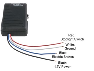
Curt Brake Controller Wiring Diagram 30.12.2018 2 Comments The red wire from your Curt brake controller is for the stop light switch and will Wiring Diagram for the Curt 4 Pole to 7 Pole Adapter # C And Wiring for. CURT part# - male quick plug with pigtails. • CURT part# - brake control wiring kit .
Towing a trailer? let's talk about brake controllers ...
Important Information - (see the box shown in wiring the diagram). Splice the brake control module’s red wire to light green wire using a wire tap. Mar 13, · This video depicts the installation of the CURT Discovery, time activated, brake control. You must read and understand the user guide before using the product. **For use with 12 volt.
Tekonsha 3016-p trailer brake control wiring harness - 2 plugs, gm
Curt Discovery Brake Controller Wiring Diagram S0456 Brake control connection harness, supplied with the tow vehicle (if equipped). • CURT quick plug adapter harness - custom connector for specific vehicles. . in the outside row of seven wires (see the box shown in wiring the diagram). Splice.
Installing a electric brake controller | jeep wrangler forums ...
CURT 51451 Quick Plug Electric Trailer Brake Controller Wiring Harness, Select Chevrolet Silverado, Suburban, Tahoe, GMC Sierra, YukonThe TRAILER brake control module is located just above the spare tire, with the chassis control module. Mount the trailer brake controller in a conve nient location somewhere near the driver. In other cases, when the trailer mounted sway …
Electronic brake wiring connector 2007 | toyota fj cruiser forum
05.06.2019 · Connector Diagram for # C57672 (included with # ETBC7) ... When it comes to wiring the brake controller you'll need to test your current wiring and you might only be able to use 1 from the bundle - the one that gets hot only when your brake pedal is pressed. Sometimes manufacturers will still install some wiring like for the brake controller even if the vehicle …
Electrical - no brakes on the panda | expandas downunder
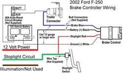
Run a 10 gauge blue wire from the tow vehicle's trailer plug "brake" terminal to the brake control. Using a 10/12 butt connector, connect this wire to the brake control's blue wire WIRING DIAGRAM NOTE:Stoplight switch connection on Ford vehicles including, Mercury Mountaineer. Do not connect to the red wire with a green stripe.
Trailer brake controller installation how-to - 5 easy steps!
Curt Venturer Trailer Brake Controller - 1 to 3 Axles - Time Delayed. (676 reviews) Code: C51110. Retail: $63.86. Our Price: $54.87. Trailer Brake Controller. Time Delayed Controller. Electric. Electric over Hydraulic.

Amazon.com: curt 51520 quick plug electric trailer brake ...
Curt Trailer Brake Controller Wiring Diagram – People comprehend that trailer is a car comprised of rather complicated mechanisms. This car is designed not just to travel 1 place to another but also to carry heavy loads. This report will be talking curt trailer brake controller wiring diagram.What are the benefits of understanding these understanding?

Curt 51432 quick plug electric trailer brake controller wiring harness, select ford f-series super duty, e-series, expedition, lincoln navigator
4l60e pcm wiring

Hayes genesis brake controller wiring diagram – nrg4cast ...
The Curt Echo Brake Controller part # C51180 is a great choice because of its convenient and simple installation. The 7-way connector that you mention part # A10-7084VP pugs into the 4-way connector you purchased part # C56217.The white wire from the 7-way plug needs to be grounded to a clean bare metal surface on the vehicle's frame.
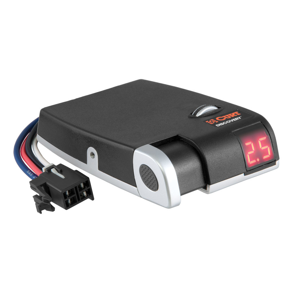
Curt discovery brake control #51120
http://www.curtmfg.comThis video is a comprehensive users guide for the CURT Discovery brake control. Some of the features of the Discovery include:Digital ...
Curt universal installation kit for trailer brake controller ...
Electric Brake Controller Wiring Diagram. Wiring Diagram. Auxiliary connection is optional, it may be connected to any 12v to 24v constant power source or left unconnected. Break away systems may be added to the service brake circuit. Elecbrakes is designed to operate 1 to 2 braked axles.
Curt spectrum trailer brake controller - 1 to 4 axles ...
Brake Controller Wiring Diagram - wiring diagram is a simplified okay pictorial representation of an electrical circuit. It shows the components of the circuit as simplified shapes, and the capacity and signal connections along with the devices. A wiring diagram usually gives guidance roughly the relative approach and concurrence of devices ...

Inspirational hayes brake controller wiring diagram | diagram ...
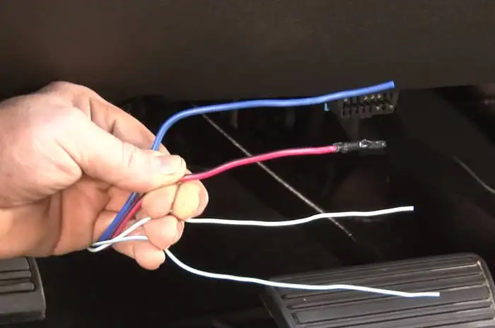
The brake control must be installed with a 12 volt negative ground system. (To install with a positive ground system use Tekonsha ® P/N 3191.) 2. WARNING Reversing BLACK and WHITE wires or improper wiring will damage or destroy brake control. 3. WARNING Be sure to solidly connect all four wires or brake control will not function properly. 4.

Amazon.com: curt triflex brake control & wiring for avalanche ...
Trailer brake control wiring diagram how to wire up a curt controller on 2011 chevy silverado etrailer com universal kit for controllers 10 gauge wires accessories and parts c51500 installation 7 way rv c57186 venturer sku 51110 56 36 by manufacturing 5 easy steps troubleshooting installations tx 51140 ron s toy discovery 51120 red light comes intermittently product… Read More »
Curt 51120 discovery electric trailer brake controller, time ...
Visit a CURT authorized installer to install a power wire to the battery. • If the phone application cannot connect to the Echo due to an incorrect or missing ...8 pages

Brake control install: curt 51170 spectrum™ brake control
Run a 10 gauge blue wire from the tow vehicle's trailer plug 'brake' terminal to the brake control. Using a 10/12 butt connector, connect this wire to the brake control's blue wire. Connect the brake control's red wire to the cold side of the tow vehicle's stoplight switch using a wire tap.

Universal installation kit for trailer brake controller - 7 ...
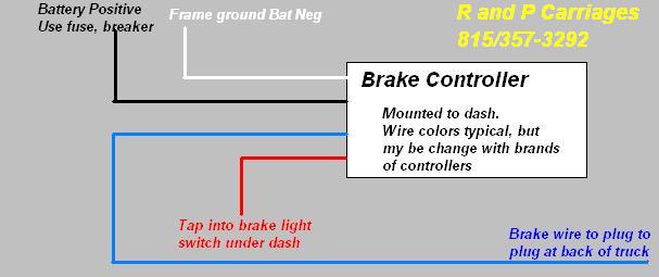
20 Oct 2019 — Wiring Diagram/Colors for Installing Curt Venturer Brake Controller. Question: We need the wire color code for this unit. We are installing ...1 answer · Top answer: The Curt Venturer part # C51110 uses the standard brake controller wiring colors of white for ground, red for stoplight switch, blue for brake output to ...
Wiring diagram for tekonsha powertrac brake controller ...
Adding a 7-Way and Brake Controller to a 1996 Isuzu NPR; Parts Needed to Install a Trailer Brake Controller on a 2007 Isuzu NPR HD; Trailer Wiring Harness Recommendation for a 1999 Isuzu NPR; Trailer Lights Not Working Using Curt 55367 on a 2000 Toyota Tundra; Determining Correct Wiring Harness for 2001 Toyota Tundra Isuzu Npr Rear Brake Adjustment Having …

Wire up your tow-pro elite - wiring diagrams | redarc electronics
Installing a brake controller involves disconnecting the vehicle battery, mounting the brake controller onto dash and plugging the unit in with a vehicle-specific wiring harness. If your vehicle is not equipped with a plug-and-play harness, you can also splice in wiring for connecting a brake controller. In this guide, we cover step-by-step how to install a brake controller.

Curt 51140 triflex electric trailer brake controller, proportional
Wiring. Wiring Diagram. Mounting the LED Display Rotary Knob. Wiring the Plug Connector to the LED ... CURT #51500 - universal brake control wiring kit.16 pages

Curt 51170 spectrum original equipment style, integrated electric trailer brake controller, proportional
Complete with a color coded trailer wiring diagram for each plug type, including a 7 pin trailer wiring diagram, this guide walks through various trailer wiring installation solution, including custom wiring, splice-in wiring and replacement wiring. If your vehicle is not equipped with a working trailer wiring harness, there are a number of different solutions to provide the perfect …
Wire diagram for installing a voyager brake controller on a ...
Curt Trailer Brake Controller Wiring Diagram Posted by Margaret Byrd Posted on November 1, 2017. 7 way wiring diagram brake controller reese troubleshooting trailer control curt universal kit for installation ford controllers harness.

Anyone have luck with a curt echo wireless brake controller ...
http://www.curtmfg.com/Search?term=51515This video depicts the Brake Control Wiring installation of the CURT brake control wiring harness with quick plug on ...

Trailer brake controller installation how-to - 5 easy steps!

Curt 51515 quick plug universal electric trailer brake controller wiring harness

Electric brake control wiring | trailer wiring diagram ...
Curt trailer brake controller harness with pigtails (packaged) #51435
Electric brake control wiring.fh10
Curt universal wiring kit for trailer brake controllers - 10 ...

Trailer brake controller harness (packaged) sku #51383 for ...
Trailer brake control wiring diagram
Trailer brake controller operation

Trailer brake controller harness (packaged) sku #51423 for ...

Wire up your tow-pro elite - wiring diagrams | redarc electronics
Troubleshooting brake controller installations | etrailer.com

Curt brake controller wiring harness installation
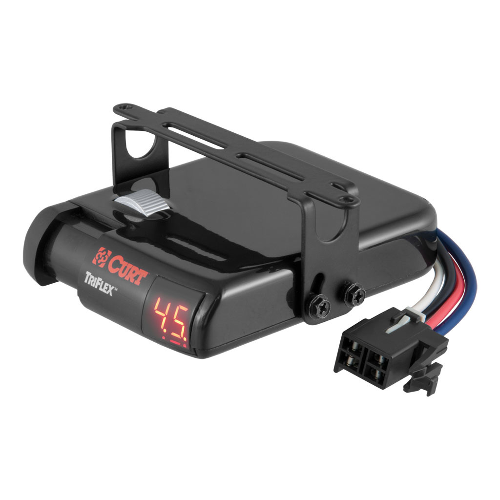
Curt triflex trailer brake controller #51140

Trailer brake controller installation how-to - 5 easy steps!
0 Response to "42 curt brake controller wiring diagram"
Post a Comment