39 hydraulic brake system diagram
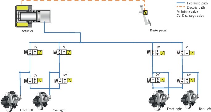
Taking one wheel's hydraulic brake circuit as an exam- ple, a schematic diagram of a hydraulic braking system is shown in Figure 1. The inlet valve (normally open) and the outlet valve (normally ...
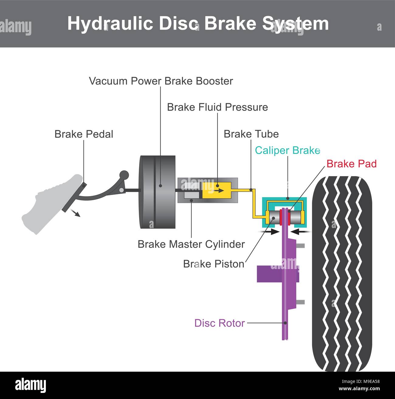
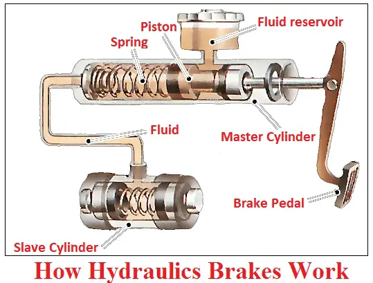
Hydraulic disc Braking System Diagram Working of Hydraulic Disc Brake : In a disc brake, the fluid from the master cylinder is forced into a caliper where it presses against a piston. The piston in turn crushes two brake pads against the disc that is being attached to the wheel, making it to stop or slow down.
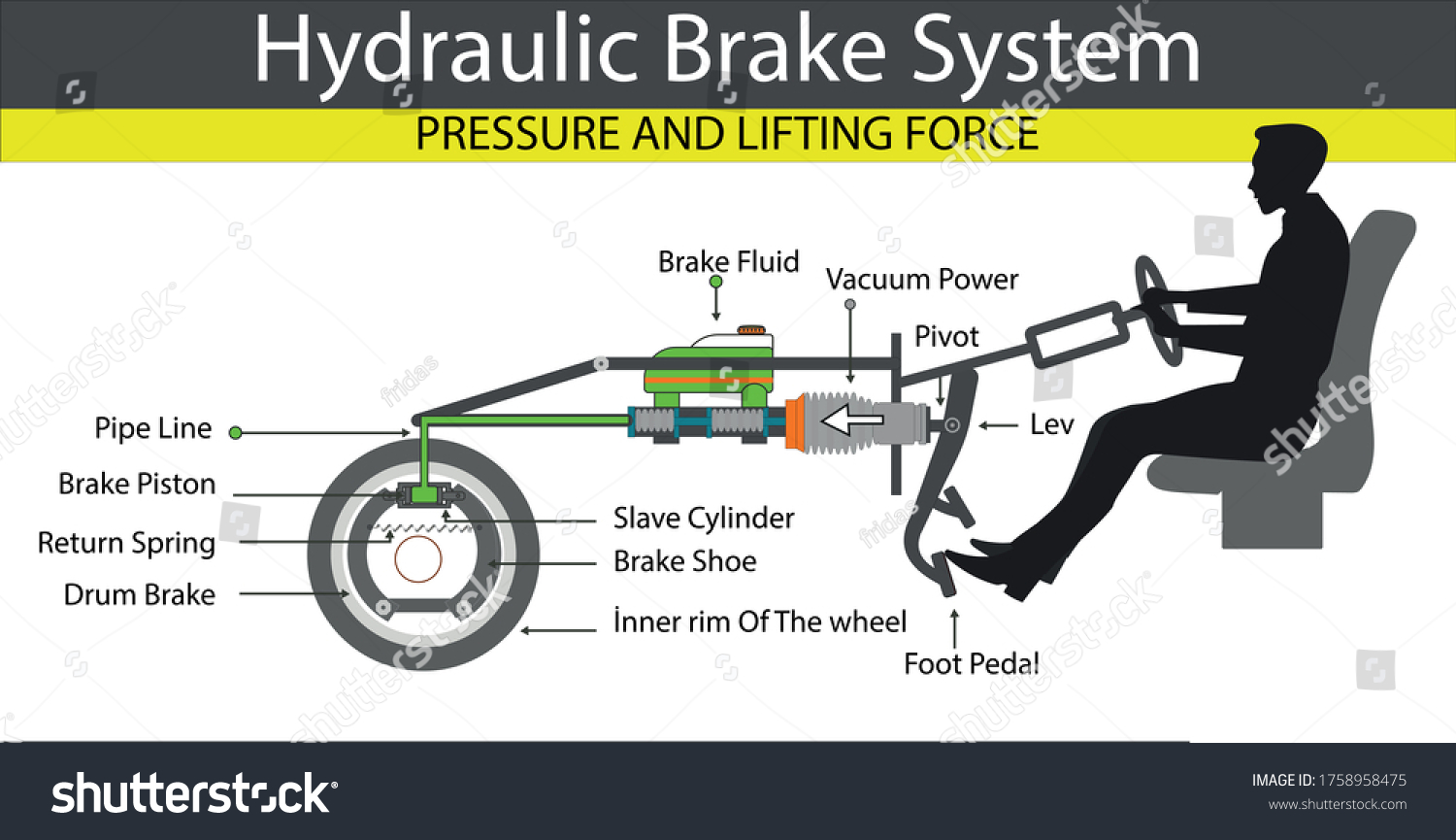
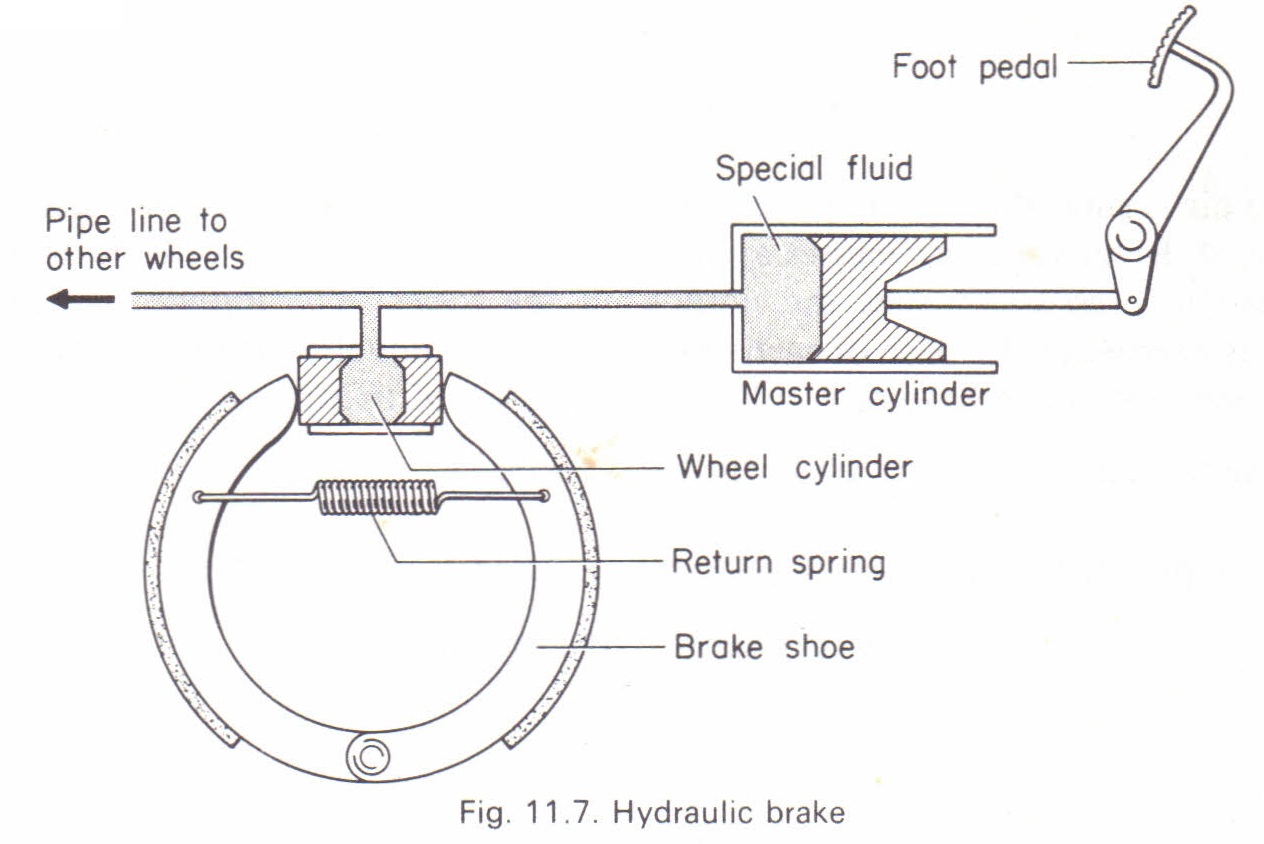
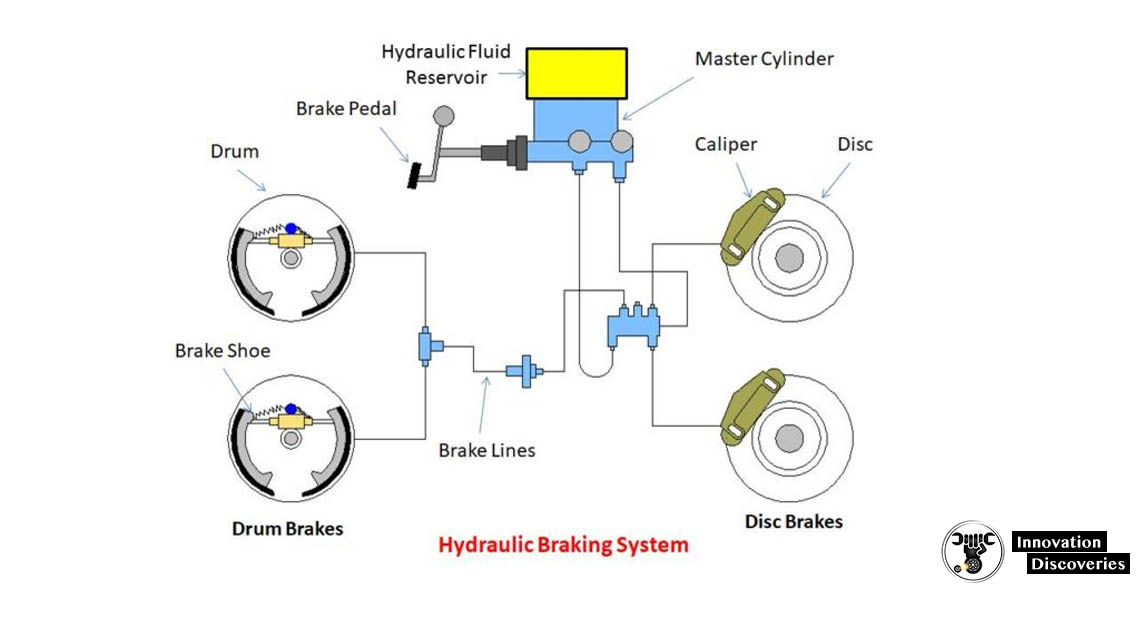
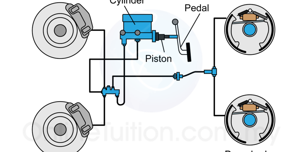
hydraulic braking system diagram The master cylinder is connected to all the four-wheel cylinders by tubing or piping. All cylinders and tubes are fitted with a fluid that acts as a link to transmit pedal force from the master cylinder to wheel cylinders. Brake Fluid The fluid-filled in the hydraulic brake system is known as brake fluid.
Hydraulic brake system diagram
The hydro-boost uses the hydraulic. Diesel engine trucks and some heavy duty gasoline trucks are equipped with the Bendix Hydro-boost system. This power brake booster obtains hydraulic. Attach the master cylinder to the hydrobooster the same way you took it off. Dont forget the brake line Here is a gm diagram I found useful.
Symbol Of Pump Used In Hydraulic System Circuit Diagram. 3. Hydraulic Motor . A hydraulic motor is a mechanical hydraulic actuator that converts hydraulic energy or hydraulic pressure into torque and angular displacement / rotation. Types Of Hydraulic Motors And Their Symbol Used in Hydraulic Circuit Diagram. 4. Hydraulic Cylinder
HEAVY-DUTY BRAKE FLUID Some hydraulic brake systems use a non-petroleum-based hydraulic brake fluid such as SAE J1703 or SAE J17021. Other hydraulic systems use petroleum-based brake fluids (mineral oil). It is important to ensure that the correct brake fluid is used in the vehicle brake system and incompatible fluids are not mixed.
Hydraulic brake system diagram.
Common pedal ratios for a manual system are 7:1 or 8:1, and 4:1 or 5:1 for power systems. Ok, lets look at the different things you will find in a typical brake system. MASTER CYLINDER. At the least in a brake system, change to a dual reservoir master cylinder. The master cylinder needs to match your braking system.
A closed system also utilises a reservoir of brake fluid, however the lack of an internal bladder to compensate for the expansion in brake fluid and also to compensate for pad wear means that any adjustments to the levels of brake fluid within the working system need to be made manually. Brake Lines. Hydraulic brake lines or hoses play the ...
HYDRAULIC DISC BRAKE A hydraulic disc brake incorporates a master piston in the lever, a hydraulic brake line, two or more opposing slave pistons in the caliper, and hydraulic fluid (DOT brake fluid or mineral oil). In a hydraulic brake system, braking is accomplished by actuating the lever, which advances the master piston inside the lever
Use only hydraulic system mineral oil (LHM) to replenish the braking and levelling systems.Do not use brake fluids (Castrol RR363,Universal or any other type).The use of any type of brake fluid, even in very small amounts,will necessitate extensive rectification to the braking and levelling systems.Always ensure when purchasing hydraulic system ...
Machines hydraulic press brake CNC system installed in high performance PLC, can be directly with ladder diagram or advanced language programming, online debugging and online editing and modification, to establish their own applications. Interpolation methods include linear interpolation, circular interpolation machines hydraulic press brake,
A hydraulic braking system transmits brake-pedal force to the wheel brakes through pressurized fluid, converting the fluid pressure into useful work of ...Spongy pedal (pedal creeps downwards): Lea...Springy pedal: Air is present in the systemPedal requires pumping: Shoes require adjust...
Definition of Brake System: A brake is one of the most important controls of the vehicle. This is a combination of some interactive parts. It absorbs energy from the moving part and slows down the vehicle with the help of friction.. Every vehicle has its own braking system to stop that vehicle.
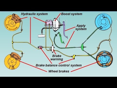
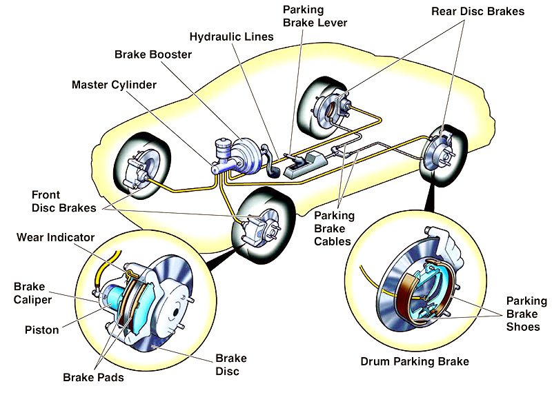
Car Brake System Diagram. In this image, you will find power booster, master cylinder, ABS, caliper assembly, ABS hydraulic unit, hydraulic fluid lines, brake pedal, rotor in it. You may also find ABS system wiring, drum, parking brake cable, electronic ABS controller, car brake system, brake system of car, car, car internal structure in this ...
Sep 26, 2020 — Today we'll be looking at the definition, functions, construction, applications, components, diagram, types, and working of the hydraulic ...Functions of hydraulic braking... · Construction · Components of hydraulic...
steps on the brake pedal. If the system is equipped with the optional power park brake, the HCU also supplies the energy to release and control the service and park brakes. The Meritor WABCO HPB system for trucks is illustrated in Figure 1.8. A complete HPB system layout, with hydraulic brake lines, appears in the Appendix. Figure 1.8 Figure 1 ...
Here are a number of highest rated Hydraulic Brake Booster Diagram pictures on internet. We identified it from obedient source. Its submitted by presidency in the best field. We understand this kind of Hydraulic Brake Booster Diagram graphic could possibly be the most trending subject when we portion it in google pro or facebook.
Brake System Diagram - Street Rod. This diagram shows a typical street rod brake system. A 2 PSI residual pressure valve (RPV) is needed in the disc brake circuit, and a 10 PSI RPV is required in the drum brake circuit as well as an adjustable proportioning valve (APV). This diagram illustrates the 2 most common types of fittings used in street ...
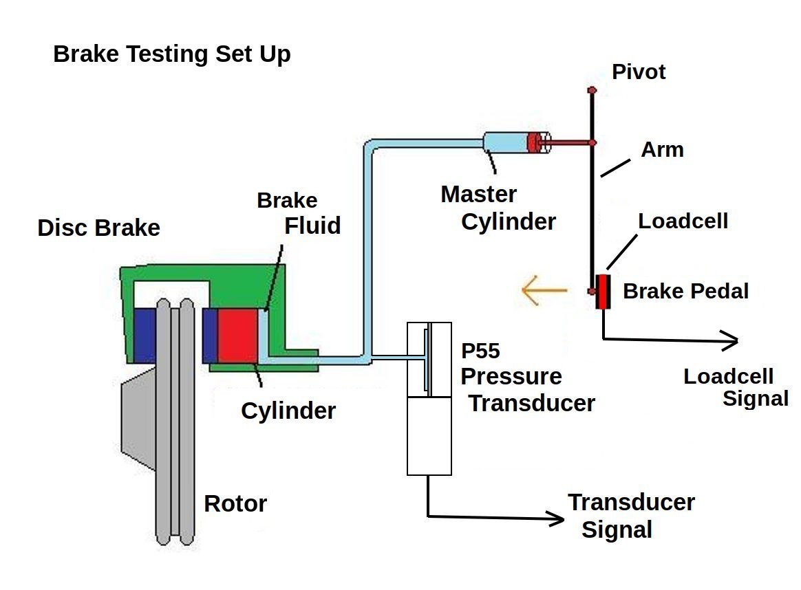
Vehicle hydraulic brake system testing | validyne engineering
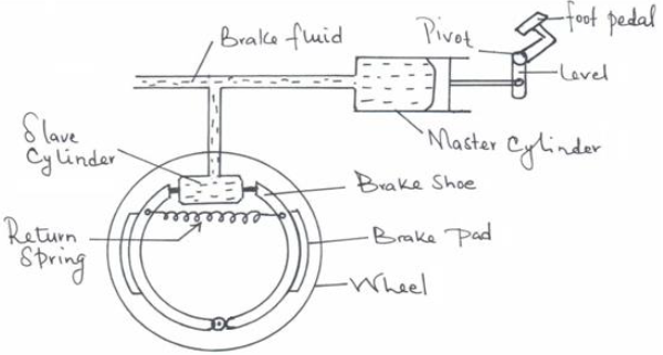
Most modern cars have brakes on all four wheels, operated by a hydraulic system.The brakes may be disc type or drum type. The front brakes play a greater part in stopping the car than the rear ones, because braking throws the car weight forward on to the front wheels.

Hydraulic brake system, when the brake pedal is pressed, a ...
Brake hydraulic system block diagram . Analytic approaches for keeping high braking efficiency and clamping efficiency of electro wedge brakes. Fig. 1 provides schematic diagrams of a conventional hydraulic brake caliper.2 A hydraulic piston pushes an inner pad.

What is hydraulic braking system? | construction of hydraulic ...
2. Double Acting Hydraulic Brakes-In double acting type of hydraulic brakes, double or tandem master cylinder is used which provides higher brake force which can be transferred in double direction i.e. both wheels in bikes and all the wheels in cars. Working of a Hydraulic Braking System. Drum Hydraulic Brake

1. general description - 1.1 dual-diagonal braking system
Hydraulic brake. A schematic illustrating the major components of a hydraulic disc brake system. A hydraulic brake is an arrangement of braking mechanism which uses brake fluid, typically containing glycol ethers or diethylene glycol, to transfer pressure from the controlling mechanism to the braking mechanism.

Schematic diagram of the hydraulic brake system. | download ...
Hydraulic brake is a type of braking system which is widely used in the automobiles with the application of the hydraulic fluid. The working principle of hydraulic braking system is purely based upon Pascal's law, which states that the intensity of pressure exerted inside a closed system by the liquid is always equal in all the directions.

Hydraulic brake system components
Hydraulic Braking system working principle: The hydraulic braking system works on the principle of Pascal's Law. PASCAL'S LAW:- The pascal law states that a "Pressure at any point in a static fluid is equal in all directions".. Hence such pascal's law is used in the hydraulic braking system to apply the brake.
Hydraulic brake system pascal principle lift stock vector ...
The disc brake rotor may break, and you may fall off the bicycle. • Vapor lock may occur if the brakes are applied continuously. To solve this problem, momentarily release the lever. Vapor lock occurs when the oil inside the brake system becomes heated, which causes the water or air bubbles inside the brake system to expand.
Hydraulic brake system, when the brake pedal is pressed, a ...
brake rotor and caliper. The wheel hub and brake assembly components should be thoroughly wetted to suppress dust before the brake shoes or brake pads are remov Wiped. e the brake parts clean with a cloth. c. If an enclosed vacuum system or brake washing equipment is not availabl e, employers may

Brakes,hydraulic brakes,brake failure, abs,abs brakes ...
Class 5 to 7 Truck & Bus Hydraulic Brake System Diagnostic Guide 4 Preface Purpose of This Diagnostic Guide The purpose of this diagnostic guide is to assist Class 5 to 7 hydraulic brake repair technicians to more accurately and quickly diagnose the most likely causes of a customer's brake related complaint.

1221 truck air over hydraulic brake system fig 121 - vehicle ...
4. The air brake system is used in trucks, buses, trains, etc. 4. Hydraulic oil brake system is used for light vehicles such as cars, light-duty trucks, etc. 5. Air compressor uses a certain amount of engine power. 5. No engine power is used. 6. It is not self lubricating. 6. Hydraulic brakes are self lubricating.
The transmission of pressure in fluids. hydraulic brake ...
Sep 25, 2019 — The major components in the hydraulic brake system circuit are connected fluid-filled master cylinder and slave cylinders. When the driver ...

Hydraulic braking system (automobile)
Hydraulic Brake System Diagram Recipes with ingredients,nutritions,instructions and related recipes.

Schematic diagram of the hydraulic brake system. | download ...
equipped with hydraulic brakes, built after August 21, 2006 feature the Meritor WABCO Full Power Brake system. The Full Power Brake system provides better pedal feel, shorter stopping distances, antilock brakes, and traction control. But the Full Power Brake system offers a lot more, like Electronic Brakeforce Distribution to compensate for axle

Hydraulic brake system.jpg (720×526) | automotive repair ...
Figure 27 Simple Hydraulic Power System. Figure 28 Line Diagram of Simple Hydraulic Power System. With an understanding of the principles involved in reading fluid power diagram, any diagram can be interpreted. Figure 29 shows the kind of diagram that is likely to be encountered in the engineering field.

Schematic diagram of the hydraulic braking system. | download ...
Car Brake System Components. Below is a list of the main components of a car brake system. We have included both the components of the disc and drum brake systems. Most modern vehicles have disc brakes on all four corners, but some economy cars still use drum brakes in the rear. 1) Master Cylinder
Full power hydraulic brake system for heavy-duty vehicles
The diagram below shows a simplified hydraulic braking system ...

Hydraulic brake - wikipedia

Explain the working of a hydraulic brake with a simple ...

Procedures for inspecting vacuum-hydraulic brakes - fire ...

Hydraulic brake | hydraulic systems, car brake system, car ...

File:hydraylic disc brake diagram.jpg - wikimedia commons
Brake system components categories
Apa itu rem hidrolik? - quora
Why are air bubbles dangerous in a hydraulic brake system?

Schematic diagram of the hydraulic braking system. | download ...
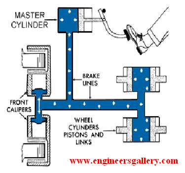
Hydraulic brake | engineers gallery

Hydraulic brake system - mech4study
Hydraulic brakes
Full power hydraulic brake system for heavy-duty vehicles

Understanding hydraulic braking system - studentlesson

Rem utama bus dan truk : tiga macam - otoblitz.net | otoblitz.net

Hydraulic brakes - parts, working, diagram, advantages and ...

Explain the working of a hydraulic break with a simple ...
How the braking system works in a car | car construction

What is hydraulic braking system? | construction of hydraulic ...
Virtual simulation of an electro-hydraulic braking system ...
What are brake hydraulics & how do they work? - buybrakes.com
0 Response to "39 hydraulic brake system diagram"
Post a Comment