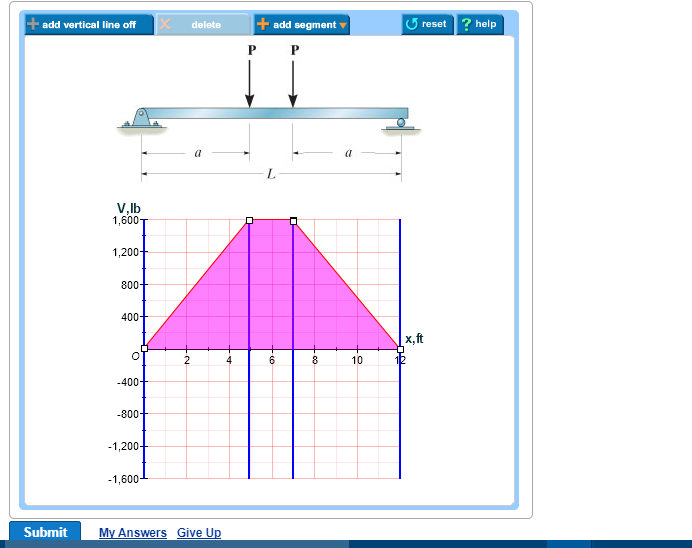
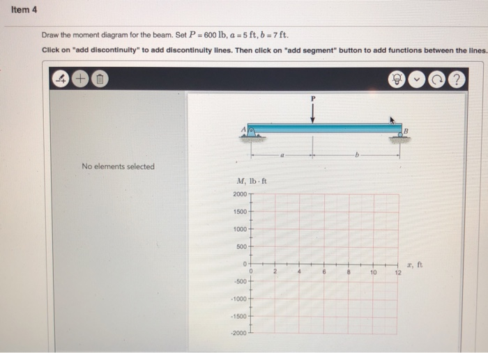
43 draw the shear diagram for the beam. set p = 600 lb, a = 5 ft, b = 7 ft.
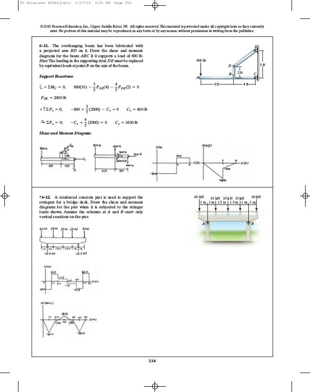
3 ft 5 ft B C 4 ft A The free-body diagram of the beam's right segment sectioned through an arbitrary point shown in Fig. a will be used to write the shear and moment equations of the beam. *6-4. Draw the shear and moment diagrams for the canti-lever beam. 2 kN/m 6 kN m 2 m A ‚ (1) a+©M = 0; -M - 2(2 - x)c ‚(2) 1 2 (2 - x)d - 6 = 0 M ...
Problem 5.152 300 5.152 Draw the shear and bending-moment [fagrarns for the beam and loading shown, and determine the maximum absoiute value (a) Of the shear. (b) of the bending . 5 0-07S Areas N - 300 -goo O N V Goo V 600 - 300 300 N 120 300 00 020) o GO 190 - - (0.2 ISO -60 O Goo N 180
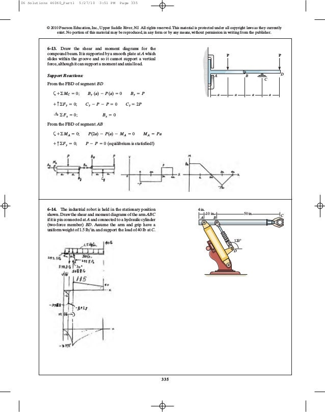
Members ABC and BD of the counter chair are rigidly connected at B and the smooth collar at D is allowed to move freely along the vertical slot. Draw the shear and moment diagrams for member ABC. A D B C P ϭ 150 lb 1.5 ft1.5 ft 1.5 ft 06 Solutions 46060_Part1 5/27/10 3:51 PM Page 333 7.
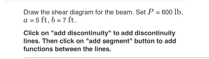
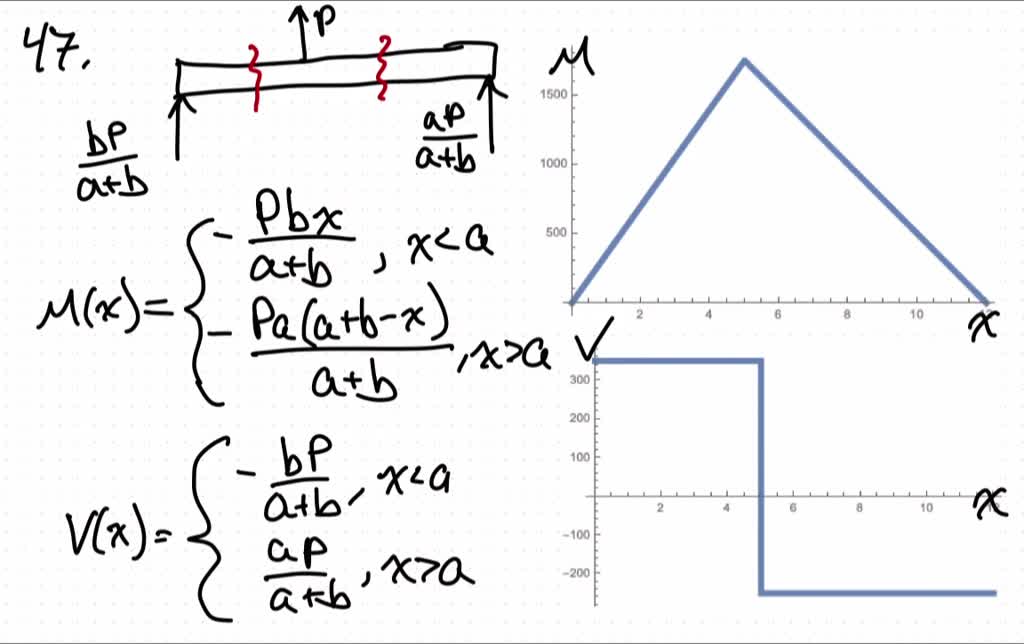
Draw the shear diagram for the beam. set p = 600 lb, a = 5 ft, b = 7 ft.
6 14 draw the shear and moment diagrams for the beam. 3. 5x} kip # ft,For 10 ft 6 x … 15 ft:V = - 0. Consider the forces to the left of a section at a distance x from the free end. — 1. 1) Under the shear diagram, drop vertical lines at every point of interest including every time the shear diagram crosses the axis, and at concentrated moments.
F.1 (b), the positive sign convention is (a) tension axial force, (b) shear forces that produce clockwise moments and (c) bending moments that result in tension stresses in the interior frame fibers. The sign convention of F.1(b) can be seen to be equivalent to the beam sign convention rotating columns AB and CD to line up with beam BC.
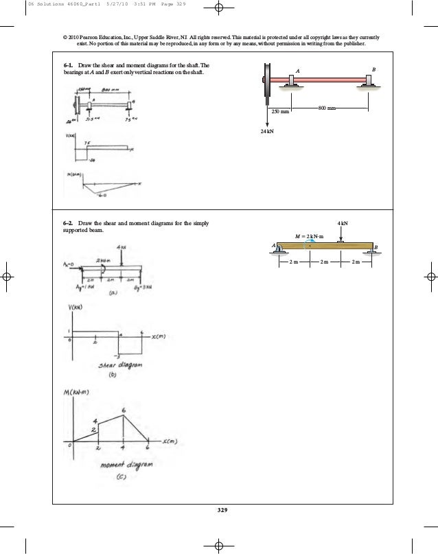
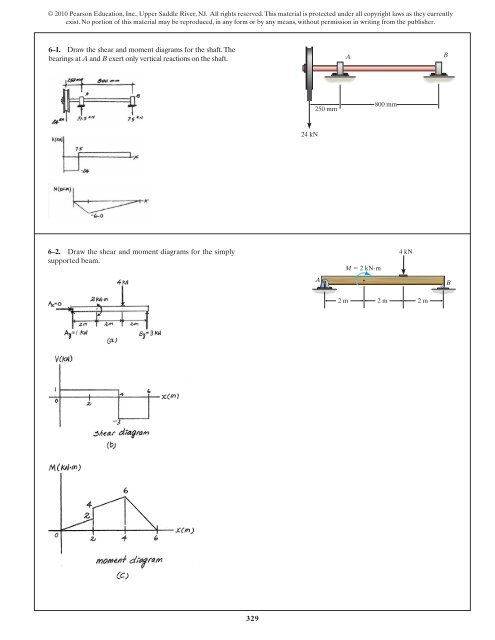
A reinforced concrete pier is used to support the 60 kN 35 kN 35 kN 35 kN 60 kN stringers for a bridge deck. Draw the shear and moment 1 m 1 m 1.5 m 1.5 m 1 m 1 m diagrams for the pier when it is subjected to the stringer loads shown. Assume the columns at A and B exert only vertical reactions on the pier.
Draw the shear diagram for the beam. set p = 600 lb, a = 5 ft, b = 7 ft..
Beam Stiffness Step 5 - Assemble the Element Equations and Introduce Boundary Conditions Consider a beam modeled by two beam elements (do not include shear deformations): Assume the EI to be constant throughout the beam. A force of 1,000 lb and moment of 1,000 lb-ft are applied to the mid-point of the beam. Beam Stiffness
Draw the shear and moment diagrams for the beam shown in Fig. 6–7a. (a) L w 0 w —— 2 0 L (b) 2– L 3 w —— 2 0 L — 3 w 0 L2 w 0 Solution Support Reactions.The distributed load is replaced by its resultant force and the reactions have been determined as shown in Fig. 6–7b. Shear and Moment Functions.A free-body diagram of a beam ...
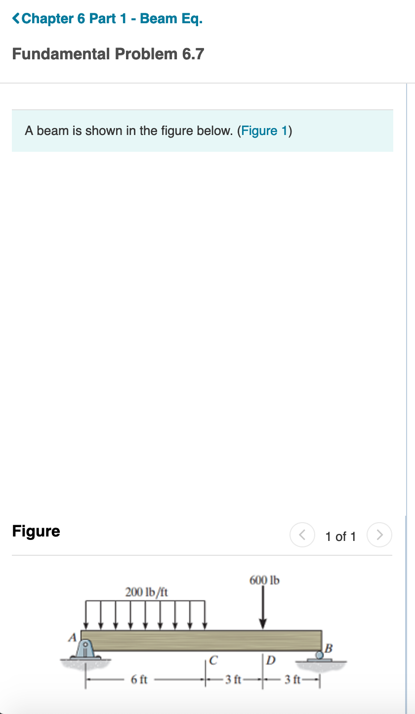
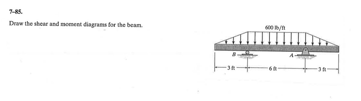
Solution for Draw the shear and moment diagrams for the beam. 600 lb/ft B 3 ft 6 ft 3 ft. menu. Products. Subjects. Business. Accounting. Economics. Finance ... Draw the shear and moment diagrams for the beam. 600 lb/ft B 3 ft 6 ft 3 ft. close. ... A tacheometer was set up at B.M and the following observations were made with a leveling staff ...
No portion of this material may be reproduced, in any form or by any means, without permission in writing from the publisher. •7–97. The cable supports the loading shown. Determine the horizontal distance xB the force at point B acts from A. Set P = 40 lb. xB A 5 ft B P 8 ft C 2 ft D 5 3 4 30 lb 3 ft 7–98. The cable supports the loading ...
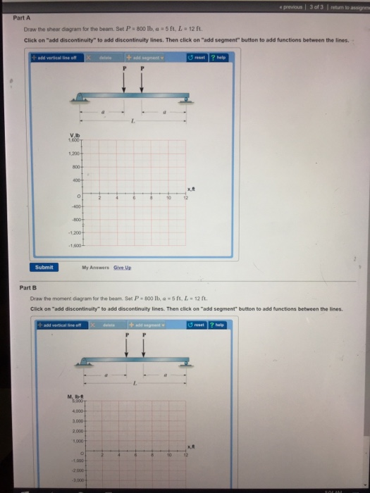
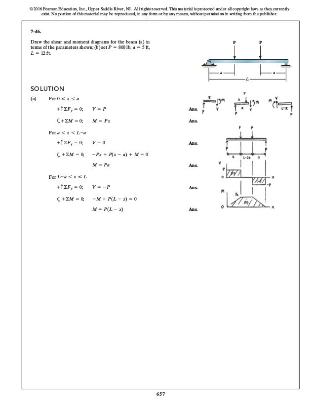
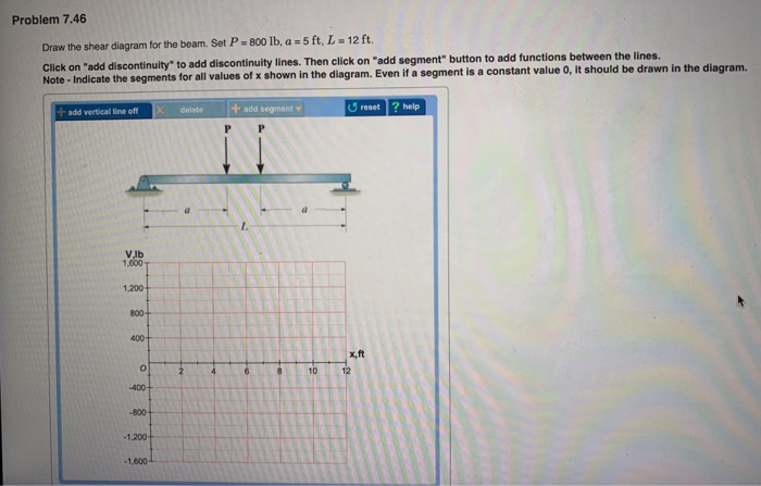
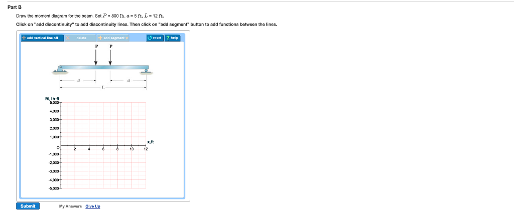
Mechanical Engineering questions and answers. Draw the shear diagram for the beam. Set P = 800 lb, a = 5 ft. L = 12 ft. Click on "add discontinuity" to add discontinuity lines. Then click on "add segment" button to add functions between the lines. Draw the moment diagram for the beam.
Free online beam calculator for generating the reactions, calculating the deflection of a steel or wood beam, drawing the shear and moment diagrams for the beam. This is the free version of our full SkyCiv Beam Software. This can be accessed under any of our Paid Accounts, which also includes a full structural analysis software.
CE 405: Design of Steel Structures - Prof. Dr. A. Varma • In Figure 4, My is the moment corresponding to first yield and Mp is the plastic moment capacity of the cross-section. - The ratio of Mp to My is called as the shape factor f for the section. - For a rectangular section, f is equal to 1.5. For a wide-flange section, f is equal to 1.1. ...
The beam consists of two segments pin connected at b. Set p 800 lb a 5 ft l 12 ft. B set p 800lb a 5ft. In this case 2 lbft. Draw the shear and moment diagrams for the beam a in termsof the parameters shown. If l 10 ft the shaft will fail when the maximum moment is m max 5 kip ft. Steps to draw Shear force and Bending moment diagrams. In SFD and BMD diagrams Shear force or Bending moment ...
Problem 406 Beam loaded as shown in Fig. P-406. [collapse collapsed title="Click here to read or hide the general instruction"]Write shear and moment equations for the beams in the following problems. In each problem, let x be the distance measured from left end of the beam. Also, draw shear and moment diagrams, specifying values at all change of loading positions and at
Shear and moment diagrams and formulas are excerpted from the Western Woods Use ... L = span length of the bending member, ft. R = span length of the bending member, in. M = maximum bending moment, in.-lbs. P = total concentrated load, lbs. R = reaction load at bearing ... 7-48 A R 1 Shear a b Figure 25 Beam Fixed at Both Ends-Concentrated ...
No portion of this material may be reproduced, in any form or by any means, without permission in writing from the publisher. 7-79. Draw the shear and moment diagrams for the 300 lb 200 lb/ft cantilever beam.
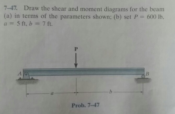
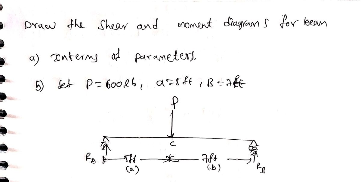
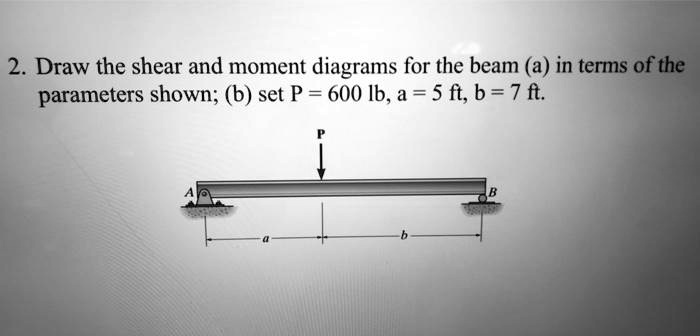
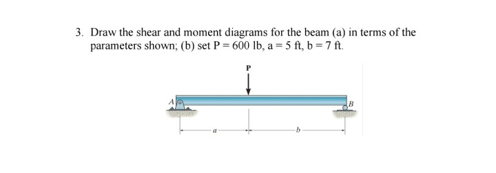
Draw the shear and moment diagrams for the beam (a) in terms of the parameters shown; (b) set P = 600 lb, a = 5 ft, b = 7 ft. 2 | P a g e 2. Draw the shear and moment diagrams for the cantilevered beam.
Solved draw the shear diagram for the beam. set p = 600 lb ...
6-5. Draw the shear and moment diagrams for the beam. 2 m 3 m 10 kN 8 kN 15 kN m M (kN m) x x ... overhanging beam. 3 ft 3 ft 200 lb/ft 400 lb 6 ft 400 lb A B M (lb ft) x (ft) V (lb) 0 400 0 12 x (ft) 600 1200 1200 300 600 400 3 6 369 12 9 Ans: Hibbeler_Chapter 6_Part 1 (487-517).qxd 2/12/13 11:07 AM Page 499. 510
Solved draw the shear and moment diagram for the beam (a) | chegg.com
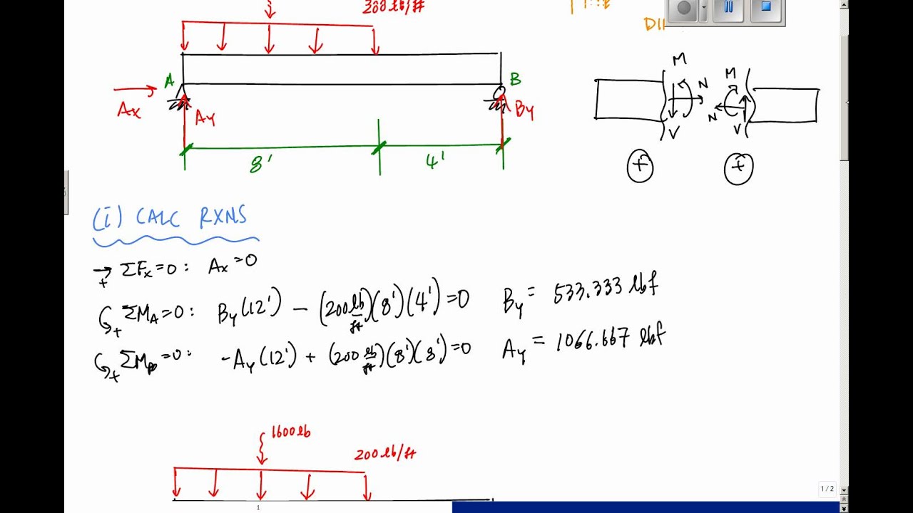
Roof: Snow +DL = 200 lb/ft Walls: 400 lb on 2nd floor beams Railing: 100 lb on beam overhang Second Floor: DL + LL = 300 lb/ft (including overhang) Roof: Second Floor: , and evaluate the shear stress. *Also select the most economical steel section for the second-floor when 3Sreq'd ≥ 165 in and evaluate the shear stress when V = 60 k.
Ch06 07 pure bending & transverse shear
Draw The Shear Diagram For The Beam Set P 800 Lb A 5 Ft L 12 Ft Then click on add segment button to add functions between the lines. Click on add discontinuity to add discontinuity lines.

Pdf) chapter | aum nuttapon - academia.edu
A concentrated load, such as P in Fig. 4.1(a). In contrast a distributed load is applied over a finite area. If the distributed load acts on a very narrow area, the load may be approximated by a line load. The intensity w of this loading is expressed as force per unit length (lb/ft, N/m, etc.)
Answered: prob. 7-47 | bartleby
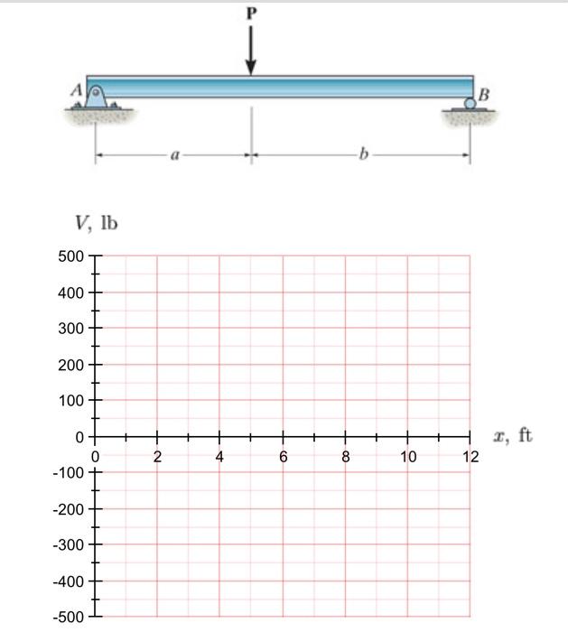
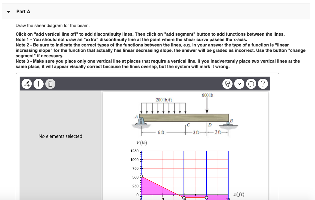
Transcribed image text: Part A Draw the shear diagram for the beam. Set P = 600 lb, a = 5 ft, b = 7 ft. Click on "add discontinuity" to add discontinuity lines. Then click on "add segment" button to add functions between the lines. + + O @ b No elements selected V, lb 500 400 300 200 100 2, ft 0+ 0 -100- 2 4 6 8 10 12 -200 -300 -400 -500 Part B Draw the moment diagram for the beam.
4 shear forces and bending moments
Problem 412 Beam loaded as shown in Fig. P-412. [collapse collapsed title="Click here to read or hide the general instruction"]Write shear and moment equations for the beams in the following problems. In each problem, let x be the distance measured from left end of the beam. Also, draw shear and moment diagrams, specifying values at all change of loading positions and at
2 draw the shear and moment diagrams for the beam (a) … - itprospt
Shear and Moment Diagrams Consider a simple beam shown of length L that carries a uniform load of w (N/m) throughout its length and is held in equilibrium by reactions R1 and R2. Assume that the beam is cut at point C a distance of x from he left support and the portion of the beam to the right of C be removed. The portion removed must then be replaced by vertical shearing
5.7 normal and shear stresses | bending of beams | informit
To draw the Moment Diagram: M AB = -50x 2 is a second degree curve; at x= 0, M AB = 0; at x = ft, M AB = -200 lb·ft.; M BC = -50x 2 + 300x - 600 is also second degree; at x = 2 ft; M BC = -200 lb·ft; at x = 6 ft, M BC = -600 lb·ft; at x = 3 ft, M BC = -150 lb·ft.; M CD = -300x + 1200 is linear; at x = 6 ft, M CD = -600 lb·ft; at x = 7 ft, M CD = -900 lb·ft.; M DE = -300x + 2400 is again ...
Solved draw the shear diagram for the beam. set p = 800 lb ...
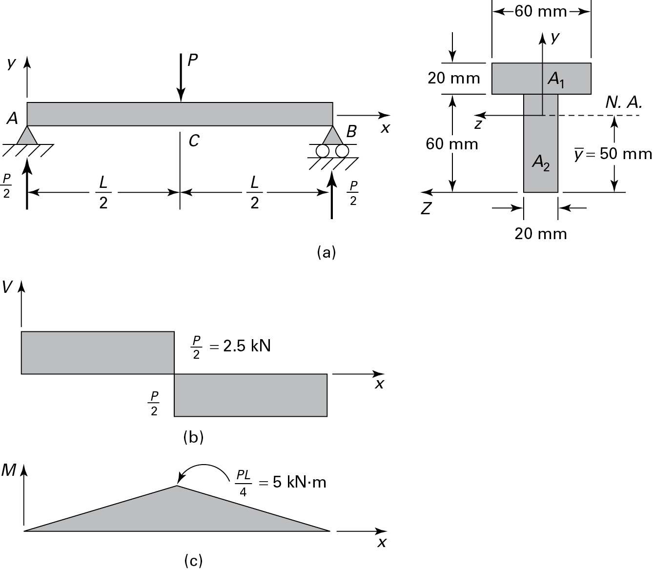
Positive bending moment diagram drawn BELOW the beam SHEAR FORCE & BENDING MOMENT DIAGRAM + M M a) Calculate the shear force and bending moment for the beam subjected to a concentrated load as shown in the figure. Then, draw the shear force diagram (SFD) and bending moment diagram (BMD). b) If P = 20 kN and L = 6 m, draw the SFD and BMD for the beam. P kN L/2 L/2 A B EXAMPLE 4 . P kN L/2 L/2 R ...

Statics 7.45 - draw the shear and moment diagrams for the shaft in terms of the parameters shown.
Images Of Draw The Shear Diagram For The Beam Set P 600 Lb A 5 Ft B 7 Ft, Easy Drawing, Images Of Draw The Shear Diagram For The Beam Set P 600 Lb A 5 Ft B 7 Ft

329 6–1. draw the shear and moment diagrams for ... - aerostudents
Chapter 7. 7.35 and 7.36 For the beam and loading shown, (a) draw the shear and bending-moment diagrams, (b) determine the maximum absolute values of the shear and bending moment.. 7.35 I knew I had to separate the beam into parts so I drew FBDs of AC, CD, DE, and EB and took the summation of forces about the y axis and set it equal zero to find my unknowns for the shear diagram.
Solved 3. draw the shear and moment diagrams for the beam | chegg.com
*7—56. Draw the shear and moment diagrams for the cantilevered beam. 300 1b - diagram of the beam's left through an arbitrary shown in fig. b will be to write the and mcnnent quations. The inœnsity the triangldar útributed load at of sectioning is — = 3333r Referring Fig. b , o V = {-300- 1b — +3001-0 The shear and diagrams shown in ...

Determine the normal, shear force, and bending moment at c and d
Draw the shear and moment diagrams for the beam. (a) in terms of the parameters shown; (b) set P = 600 lb, a = 5 ft, B = 7 ft. fullscreen Expand. Transcribed Image Text.
Chapter 7
6—25. Draw the shear and moment diagrams for the beam- The two segments are joined together at B. 8 kip 3 kip,ft 5 ft *6—20. Draw the shear and moment diagrams for the beam, and determine the shear and moment throughout the beam 10 kip 2 kip/ft g Kip 8 kip 40 kip.ft as functions of x. Support Reactions: As shown on FBD. Shear and Moment ...
Solved draw the shear diagram for the beam. set p = 600 lb ...

Drawing shear and moment diagrams for beam
Drawing shear and moment diagrams example- mechanics of materials and statics
Solved
Solved

Draw the shear and moment diagrams for the beam (a) in terms of ...

Draw the shear and moment diagrams for the beam a in terms of the ...

Drawing shear and moment diagrams for beam
Solved plz help in this question. part a draw the | chegg.com
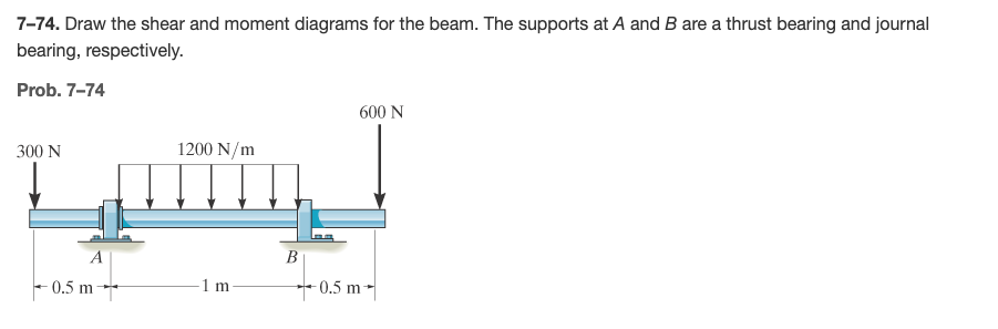
Answered: 7–74. draw the shear and moment… | bartleby

Draw the shear and moment diagrams for the beam a in terms of the ...
Ch06 07 pure bending & transverse shear
329 6–1. draw the shear and moment diagrams for ... - aerostudents
2 draw the shear and moment diagrams for the beam (a) … - itprospt
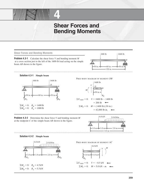
Shear forces and bending moments
Solved problem 7.46 12 ft draw the shear diagram for the | chegg.com

Pdf) shear forces and bending moments | md. shahin alam - academia.edu

Draw the shear diagram for the beam set p 800 lb a 5 ft l 12 ft ...
Solved draw the shear diagram for the beam. set p - 600 lb ...

Statics 7.71 - draw the shear and moment diagram for the beam ...
Solved problem 7.61 part a draw the shear diagram for the | chegg.com
Chapter 7
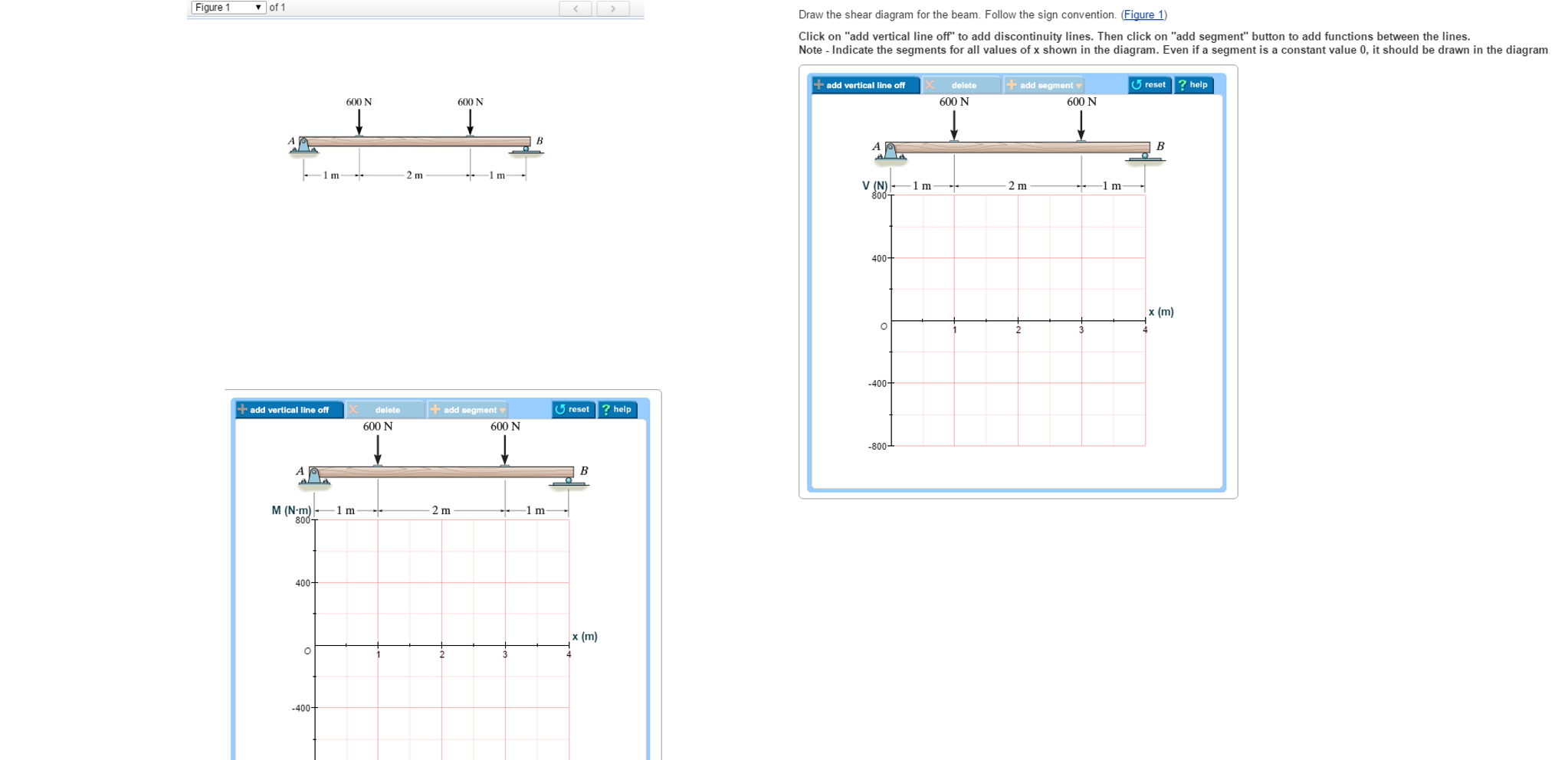
Solved draw the shear diagram for the beam. follow the sign ...
Ch06 07 pure bending & transverse shear
Answered: draw the shear and moment diagrams for… | bartleby
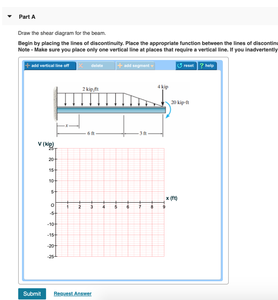
Solved problem 6.8 17 of 51> review 2 kip/it 4 kip 20 kip-ft ...
Solved part a draw the shear diagram for the beam. set p 800 ...
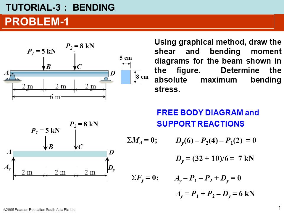
Problem-1 using graphical method, draw the shear and bending moment diagrams for the beam shown in the figure. determine the absolute maximum bending.
0 Response to "43 draw the shear diagram for the beam. set p = 600 lb, a = 5 ft, b = 7 ft."
Post a Comment