43 free energy generator circuit diagram
We suggest an innovative architecture for an efficient energy generator devoted to the powering of a wireless sensor network deployed for aircraft health ... Dec 24, 2019 — It works on the principle of Neodymium magnets whereas a normal generator works on the principle of electromagnetic Induction. Examples of free ...
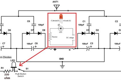
A free energy collector circuit helps to convert surrounding radio frequency waves to electric power and can provide 40 watts to 10 watts indefinitely.

Free energy generator circuit diagram
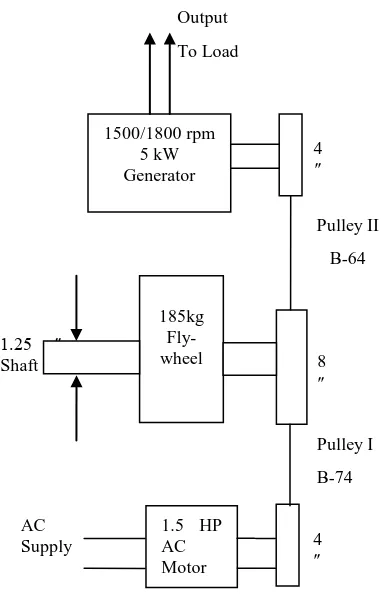
Nov 4, 2021 — This circuit is very clever as the DC motor/generator automatically adjusts the running of the AC motor both at startup and under varying ... Jun 15, 2019 — Analyzing the free energy generator circuit: ... if this is true then the above idea could revolutionize the power generation concept. In the Fig. 5 circuit, the magnitude of timing resistor R3 has to be significantly bigger compared to R1, but lower than the product of R5 and the hFE of Q1. The pulse time in Fig. 5 is 50 milliseconds divided by the value of capacitor C1 in microfarads. With the value of Cl as indicated in the diagram, pulse timing output will be 5 seconds.
Free energy generator circuit diagram. Get Images Library Photos and Pictures. Free Energy Devices Moving Pulsed Systems Doitpoms Tlp Library Phase Diagrams And Solidification Phase Diagrams 1 Plos One Cooperative Interactions Between Different Classes Of Disordered Proteins Play A Functional Role In The Nuclear Pore Complex Of Baker S Yeast Motor Generator Circuit Bedini Motor Generator Schematic Free Energy Rangkaian Elektronik ... 3 days ago — A free energy generator is a special type of device used to generate ... capacitor in the first parallel circuit and draw a circuit diagram. 12V to 120V Inverter Circuit. Last Updated on November 22, 2021 by admin Leave a Comment. The proposed 12 V DC to 120 V AC inverter circuit is essentially a push-pull audio amplifier, as illustrated in the diagram below. A 5 volt square wave serves as […] 100+ Electrical & Electronic Circuit Symbols. March 19, 2021. By Administrator. Electrical symbols or electronic circuits are virtually represented by circuit diagrams. There are some standard symbols to represent the components in a circuits. This article gives some of the frequently used symbols for drawing the circuits.
Electrical circuits consist of a system formed by a set of connected electrical elements. It has one or more closed paths that can be traversed by an electric current. An electric current is the movement of free electric charges in an orderly manner. Usually, these charges are electrons that move from the negative terminal to the positive terminal. The free energy generator is a device, which is used to generate ... First, make a circuit diagram by connecting capacitors in a parallel circuit, ... The circuit diagram of this strange circuit is demonstrated in below diagram. The three inverters are attached as a kind of Schmitt trigger, and this form of circuit is completely managed in the subsequent chapter. As a result only the features of the Schmitt trigger circuit will be viewed as, instead of exactly how this circuit in fact functions. www.amazon.com Blue Sea 40A Circuit Breaker www.amazon.com Shurflo Water Pump 3 GPM www.amazon.com Blue Sea 12V Socket www.amazon.com Sterling BB1260 60A Battery to Battery Charger www.amazon.com Blue Sea ST Blade 12 Circuit Fuse Box www.amazon.com Blue Sea 100A Circuit Breaker www.amazon.com Blue Sea 100A Circuit Breaker
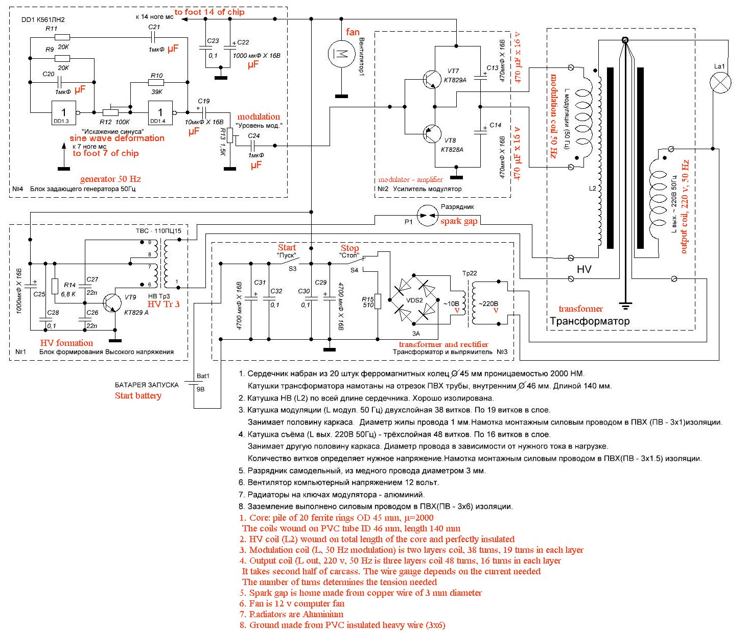
The circuit can be also used in mosquito swatter bat application by replacing the iron cored transformer with a ferrite core counterpart. High Power 10 kv Generator Circuit. If powered with a 30 V power input, the circuit detailed below can provide a high voltage which range from 0 to 3 kV (type 2 an even provide from 0----10 kV. Test the circuit. (Refer to the Circuit Test video listed in the Additional Multimedia Support section.) Turn the multimeter to the 20V DC setting and start tapping on the piezo element. Expect to see the voltage across the capacitor increasing, which indicates that it is storing energy. If not, try flipping the switch to the opposite position. This one represents the high level building blocks of a stand-alone system. I sketched a diagram: It all starts with a solar panel or panels. The solar panel (or panels) connect to a charge controller. The charge controller connects with the panel (s) and the battery (or battery bank, if more than one). It manages the power coming in from the ... Need Schematic Drawing Of Onan 300 3763 Circuit Board Irv2 Forums. How to wire a onan 6 5 nhe 1r emerald 940 0121 5nh spec p rv genset 5500 generator wiring diagram installation guide nh i have 1977 dodge executive motorhome up remote start serv manual pg 33 40 manualzz fuel pump voltage source my starter only spins free energy plans service mins 900 0184 yd generators controls relays function ...
Ripple factor in a bridge rectifier. The circuit diagram below shows a half wave rectifier with capacitor filter. Image Result For 12v Rectifier Regulator Wiring Diagram Regulators Power Source Wire Panel where the rectifier are open causing high ripple or a c voltage while charging volts and amps are still. Rectifier regulator wiring diagram. Wipac …

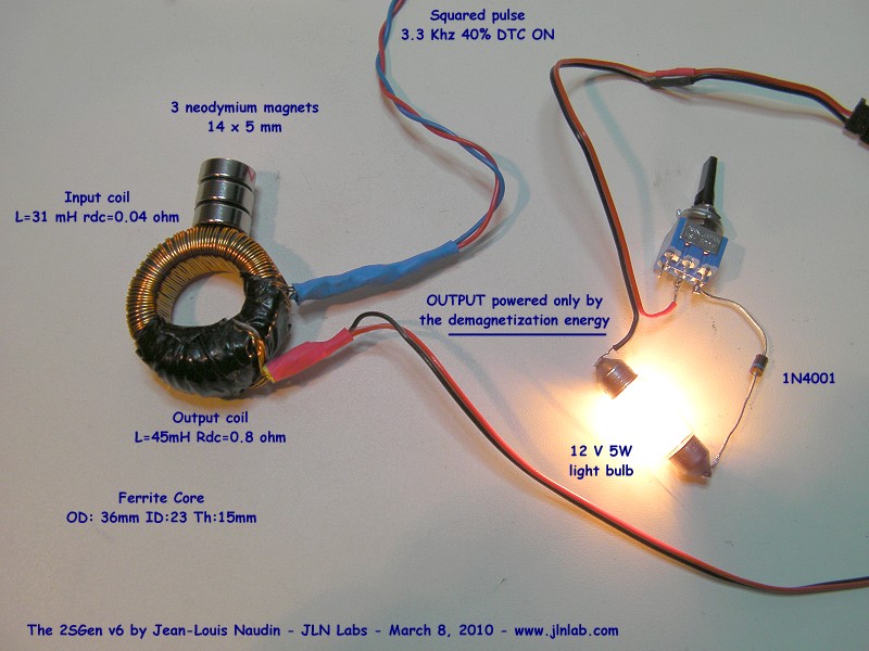
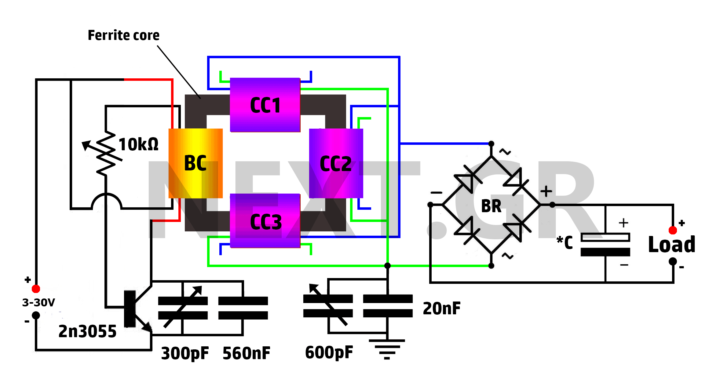
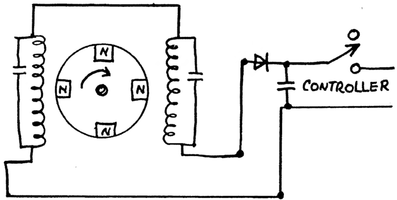
A free energy enthusiast from South Africa who doesn't want to reveal his name has generously shared the details of his solid state self-powered generator for all the interested free energy researchers. When the system is used with an inverter circuit, the output from the generator is around 40 watts.

Free Electronic Circuit Diagrams. Amarante Pruvost. November 19, 2021. November 19, 2021. A Collection Of Free And Paid Circuit Drawing Softwares Which Can Be Used To Draw Wiring Diagrams Schematic Circuit Diagram Drawing Software Schematic Drawing. Free Electronic Circuits Project Diagram And Schematics Electronic Circuit Projects Circuit ...

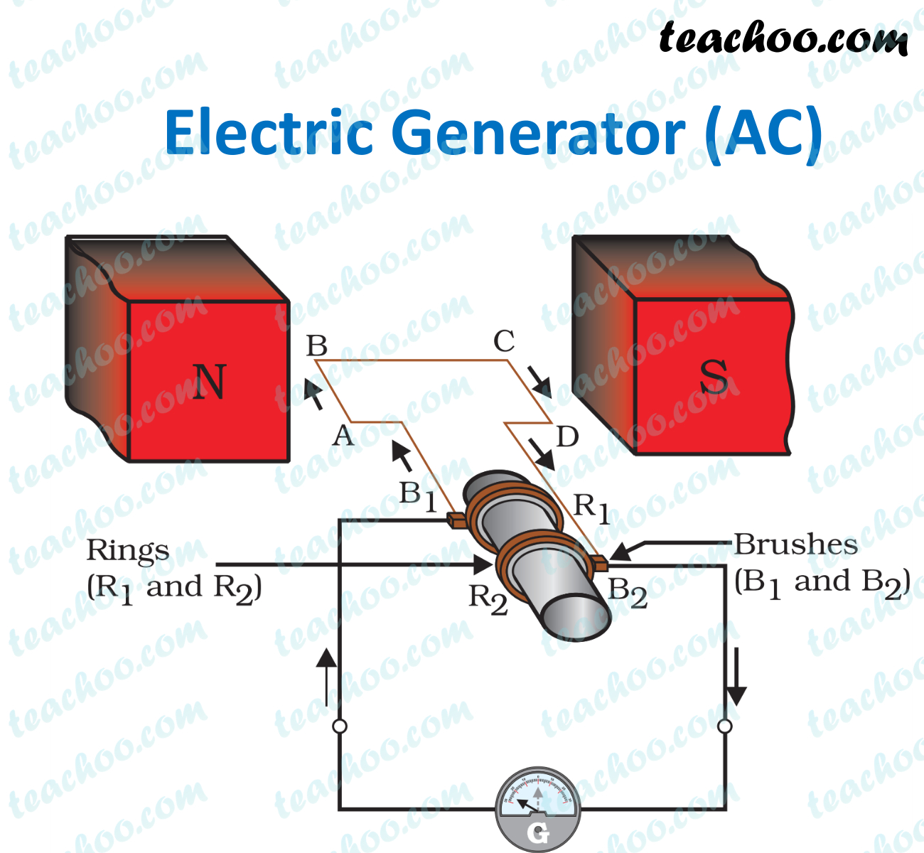
Electric Generator works on the principle of electromagnetic induction. Electromagnetic induction is the phenomenon of the generation of electric current in a circuit by changing the magnetic flux linked with the circuit. Magnetic flux is the total number of magnetic field lines passing through a particular area.

How does a generator work? Take a length of wire, hook it up to an ammeter (something that measures current), and place it between the poles of a magnet. Now move the wire sharply through the invisible magnetic field the magnet produces and a current will briefly flow through the wire (registering on the meter). This is the basic science behind the electricity generator, demonstrated in 1831 ...

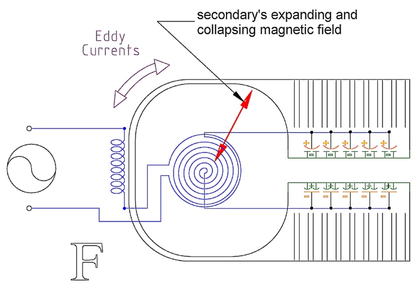
/ Free Energy / Motionless Electromagnetic Generator (MEG) ... A term MEG refers to motionless electromagnetic generator circuit which is designed to generate electrical energy without using any moving components or involving any kind of mechanical stages. How a MEG Device Woks ... The following circuit diagram can be effectively used for ...
3) Inverter Circuit Using IC SG3524. This 3rd design is easy to build, the output power of 150W, the present simple inverter circuit using IC SG 3524 design frequency of about 300HZ, the purpose is to reduce the volume of the inverter transformer, the weight, the output waveform is a square wave.
A generator in electrical circuit theory is one of two ideal elements: Every practical generator needs a prime mover to rotate its armature. The Electrical Circuit Diagram, Basic Navy Training from www.rfcafe.com Free cliparts that you can download to you computer and use in your designs.
Hho Free Hho Plans Hydrogen Generator Free Energy How To Plan . Residential Plumbing Diagrams Hot Water Circulation Diesel Generator Control Panel Wiring Diagram Residential Plumbing Plumbing Diagram Tankless Water Heater . My Catch Can X2f Pcv Setup Using Moroso Air X2f Oil Separator E46fanatics Bmw Canning Setup . Pin On Landscaping Design Ideas
There are three types of circuits: open circuit, close circuit, and short circuit. When the switch is in the off condition it is known as an open circuit. The terminology related to the switch varies between the US and the UK. In the UK they refer to 2-way switches and cross-over switches. While the US refers to a three-way switch and 4-way switch.
Closed Circuit Diagram (Reference: dipslab.com) Difference between Open Circuit and Closed Circuit. We are comparing the basic points about open circuit vs closed circuit in this section: Fundamentals. An open circuit creates an insufficient channel for active energy to pass from the source to the load.
Wiring diagram 30 amp 240 volt circuit breaker. The standard 240 volt portable generator plug is a four wire nema l14 30 plug that can be found in most hardware stores. A wiring diagram is a simplified conventional pictorial representation of an electric circuit. This outlet is commonly used for a heavy load such as a large air conditioner.

A single-line diagram (SLD) is a high-level schematic diagram showing how incoming power is distributed to equipment.. A4.1.1 Single-Line (One-Line) Diagram: A diagram which shows, by means of single lines and graphic symbols, the course of an electric circuit or system of circuits and the component devices or parts used therein.
Designing a Windmill Generator. A simple windmill generator circuit concept presented here can be built by any hobbyist for charging small batteries at home, completely free of cost and with negligible efforts. Bigger models of the same can be tried for achieving greater power outputs which may be used for powering small houses.
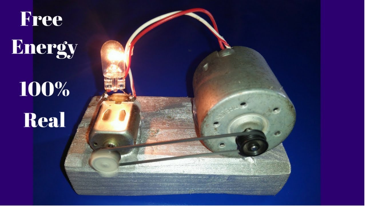
Description : I am show about free energy generator using neodymium magnetic field. the magnets create a magnetic field, the copper coil absorb from magnetic field and convert the energy. Components Needed: 1. Copper Coil : i). The copper coil are winding on pvc pipe. ii). The pvc pipe dia are (20mm, 32mm) 2. DC Motor i).

One is a more common inverter circuit diagram. The above is a relatively easy to produce the inverter circuit diagram, you can 12V DC power supply voltage inverter 220V mains voltage, the circuit from BG2 and BG3 composed of multi-harmonic oscillator to promote, and then BG1 and BG2 drive to control the BG6 And BG7 work.

In the Fig. 5 circuit, the magnitude of timing resistor R3 has to be significantly bigger compared to R1, but lower than the product of R5 and the hFE of Q1. The pulse time in Fig. 5 is 50 milliseconds divided by the value of capacitor C1 in microfarads. With the value of Cl as indicated in the diagram, pulse timing output will be 5 seconds.
Jun 15, 2019 — Analyzing the free energy generator circuit: ... if this is true then the above idea could revolutionize the power generation concept.
Nov 4, 2021 — This circuit is very clever as the DC motor/generator automatically adjusts the running of the AC motor both at startup and under varying ...


0 Response to "43 free energy generator circuit diagram"
Post a Comment