45 power antenna wiring diagram
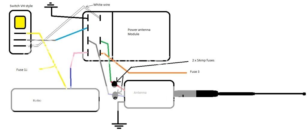
The problem is that the power contector isn't made into the 95 wiring. The antenna has five wires going into it and I need to know what they are for. I have a old factory service manual but since it is older it does even list a power antenna. I have done a search and having come up with anything. So any help you can give me would be greatly ... Wiring Aftermarket Power Antenna into Factory Wiring ... PS - I looked at the wiring diagrams for each year 87-92 and they all appeared to have the same hookup to the original power antenna so this should be able to be applied to all years. Save Share. Reply.
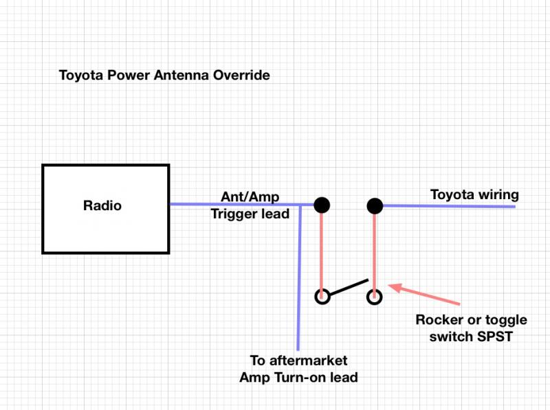
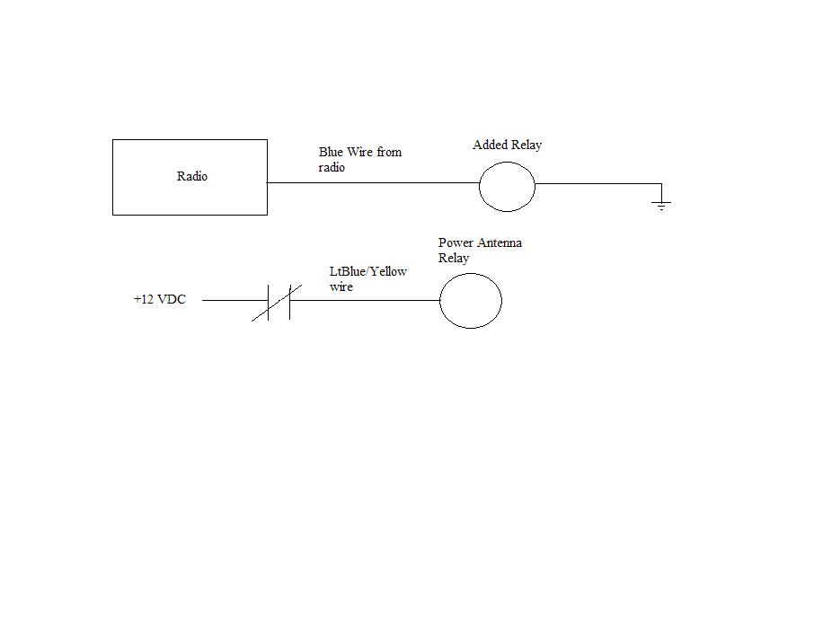
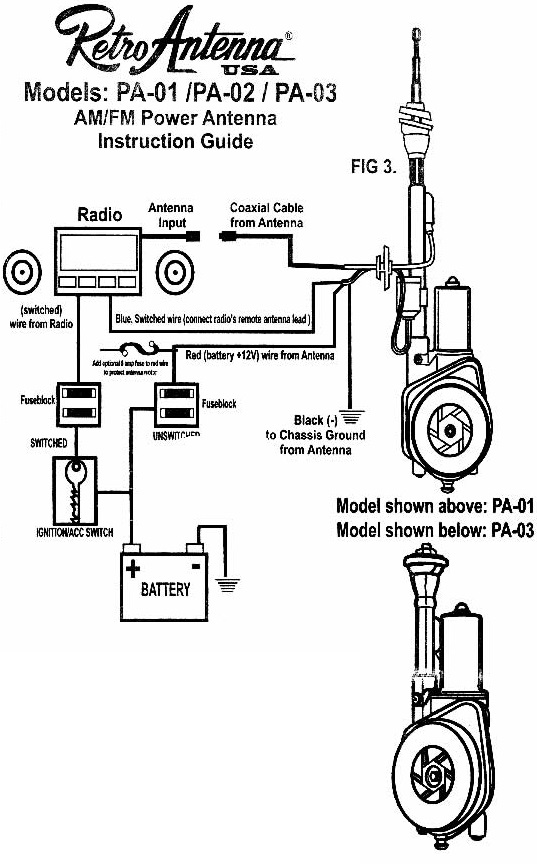
power switch. Solder blue wire as shown in figure 3. Reassemble radio top or back cover. Then reinstall radio in vehicle. Connect the new blue wire from the radio to the blue wire from the antenna. Connect coaxial cable from antenna to radio. C) The red power wire from antenna can be connected at fuse block, ( as shown in figure 2.) battery, or ...

Power antenna wiring diagram
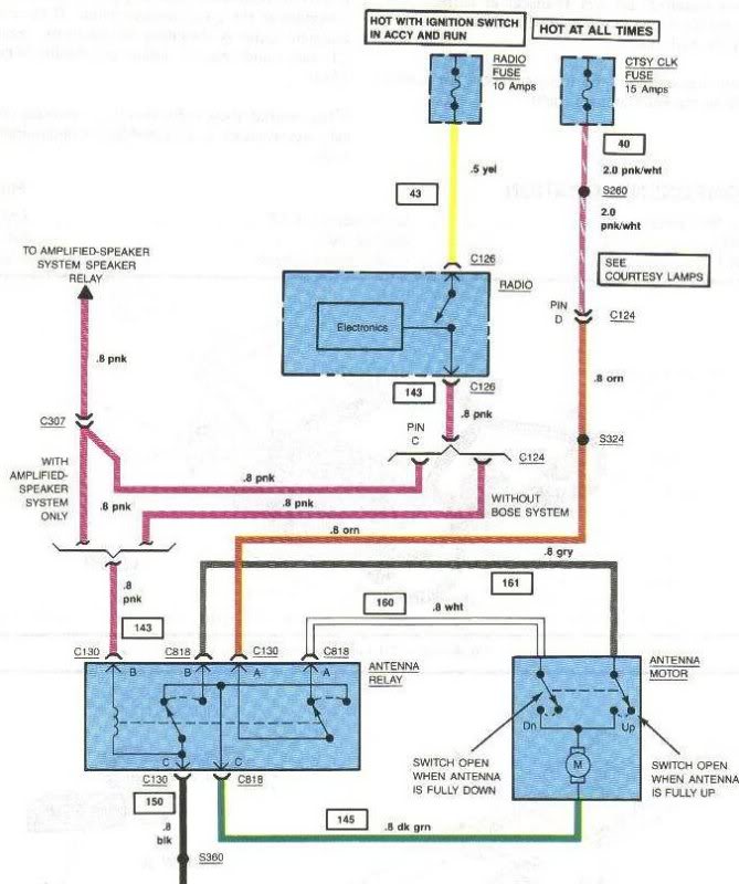
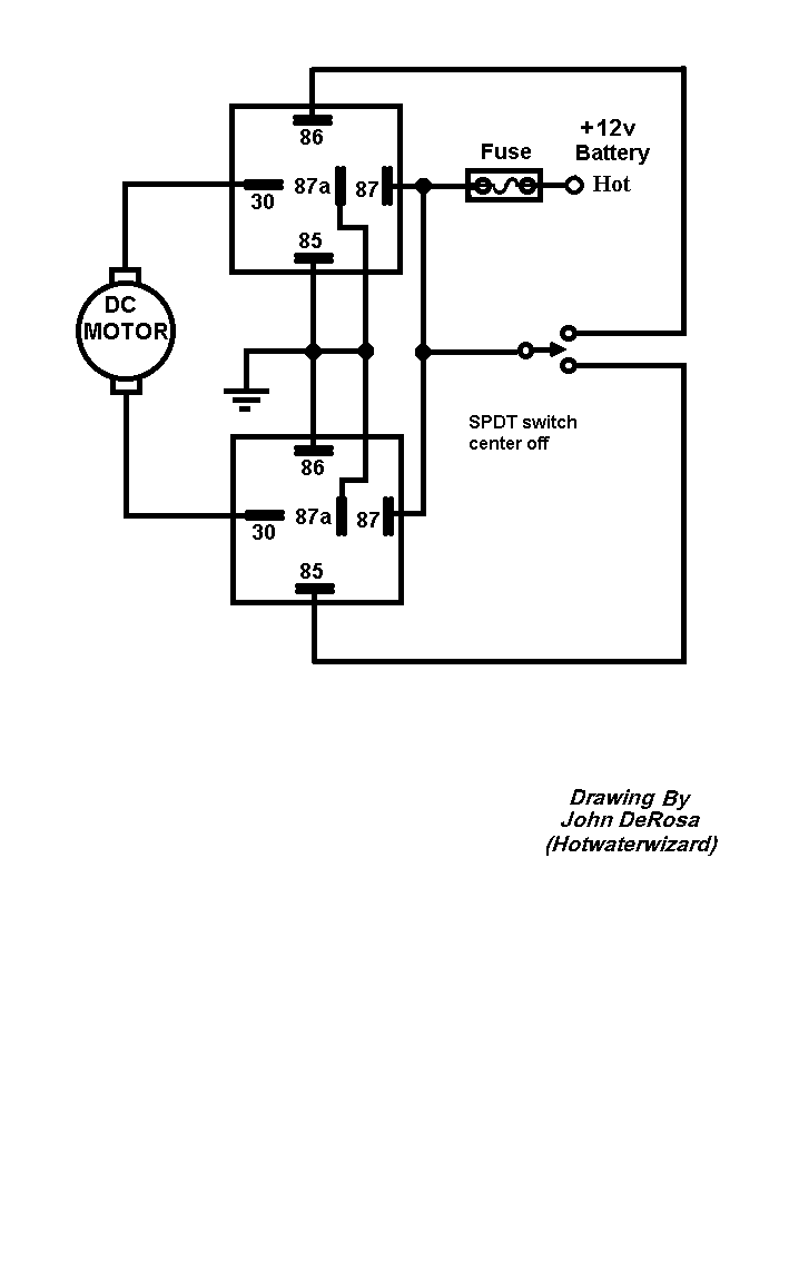
here this diagram electric for power anten with 2 wires or 3 wires as the riviera. there are 2 relays. on the new power antenna (as you can buy on the internet) you just have to find the 2 wires that feed the motor of the new power antenna + and - and you don't use the wire of autoradio signal. Installation of an Electric or Powered Antenna is fairly simple, you just need to ensure you have adequate space under the wing for the motor body of the antenna (or use the PA-02 remote motor antenna). You will also need to run power to the antenna along with the coaxial lead. Wiring the antenna is simple, there is a constant (+12v) feed ... Car Power Antenna Wiring Diagram - wiring diagram is a simplified suitable pictorial representation of an electrical circuit. It shows the components of the circuit as simplified shapes, and the skill and signal connections amongst the devices. A wiring diagram usually gives guidance more or less the relative face and concurrence of devices ...
Power antenna wiring diagram. The red wire is hooked to a constant 12v source, the green wire is hooked to a conditional 12v source, usually a power source from the radio that is controlled with the radio on/off switch and the remaining black wire is connected to ground. The green wire provides power to raise the antenna. When the power from the green wire is removed(i.e ... 1998 Chevrolet Corvette Car Stereo Radio Wiring Diagram. Radio Constant 12V+ Wire: Orange. Radio Switched 12V+ Wire: Yellow. Radio Ground Wire: Black. Radio Illumination Wire: Gray. Radio Dimmer Wire: Brown. Radio Power Antenna Trigger Wire: Pink. Radio Amplifier Turn On Trigger Wire: N/A. Front Speakers Size: 4? CHEVROLET Car Radio Stereo Audio Wiring Diagram Autoradio connector wire installation schematic schema esquema de conexiones stecker konektor connecteur cable shema car stereo harness wire speaker pinout connectors power how to install ... +12 V Direct) ( A5 Antenna Output +) ( … Half power beam width is the angle in which relative power is more than 50% of the peak power, in the effective radiated field of the antenna. Indication of HPBW When a line is drawn between radiation pattern’s origin and the half power points on the major lobe, on both the sides, the angle between those two vectors is termed as HPBW , half power beam width.
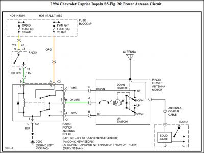
Power Antenna Relay Diagram - Hello. I'm working on my cousin's 1978 Chevrolet Monte Carlo and he asked me to try and fix the power antenna. There is power and ground at the relay switch, and the wiring coming from the power antenna seems solid, but there is no movement on the mast. I disconnected t 1998 Chevrolet Corvette Car Stereo Radio Wiring Diagram. Radio Constant 12V+ Wire: Orange. Radio Switched 12V+ Wire: Yellow. Radio Ground Wire: Black. Radio Illumination Wire: Gray. Radio Dimmer Wire: Brown. Radio Power Antenna Trigger Wire: Pink. Radio Amplifier Turn On Trigger Wire: N/A. Besides mounting a new antenna, You will also need to know how to wire the new power antenna up. After watching this tutorial you'll be well informed enough ... Winegard Antenna Wiring Diagram. Mount power supply in wall with screws provided and attach TV set cable to jack on front. Connect band separator to VHF and. UHF antenna terminals of TV set. BEFORE YOU MOUNT ANTENNA: Decide location of power supply before mounting your antenna. A wiring diagram, Figure 1, will help you determine the.
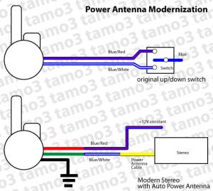
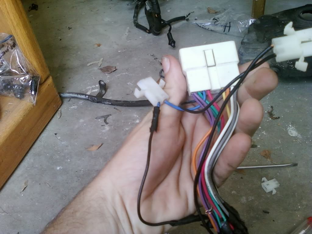
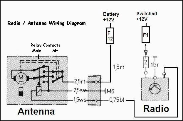
Power Antenna Wiring Diagram - wiring diagram is a simplified satisfactory pictorial representation of an electrical circuit. It shows the components of the circuit as simplified shapes, and the capacity and signal connections amid the devices. A wiring diagram usually gives assistance not quite the relative direction and deal of devices and ... At the wiring harness I have a six pin connector with five wires: Red, Blue/Red, Blue, Black/Yellow, blank and Black. On the replacement antenna I have three wires: Red, Green and Black. The only identified wire is the red as "+12v power antenna". I'm assuming that black is ground. TV Antenna wiring diagram. 1. A short coax cable is ran from the TV antenna output to the preamplifier input. Our 2.5 foot cable works well for the EZ HD antenna. The 4 foot cable is best for the HD Stacker antenna. 2. From the preamplifier output run coax cable to the ground block. (Antennas mounted indoors do not require a ground). 1974 Mercedes 450Sl Power Antenna Wiring from www.audiforums.com To properly read a cabling diagram, one offers to find out how the particular components inside the system operate. For instance , in case a module is usually powered up and it also sends out the signal of fifty percent the voltage in addition to the technician does not know this ...
19-08-2021 · Otherwise, you'll need a wiring diagram, which is sometimes printed on the exterior of the head unit or available online. Using a Head Unit Harness Adapter Although most aftermarket head units follow the above coloring scheme, and it's possible to figure out what the OEM wires in your car are for without a wiring diagram, installing an aftermarket head unit is easier if you have a harness adapter.
Mazda Miata Wiring Diagrams 1990 To 2002 Forumz Chat Forums. Power antenna mazda mx 5 miata m 1993 1997 manual part 122 2003 remote wire tap in trunk forum na wiring harness work diagram 1990 parts help non bose metra pins for sony cdx1000rf all diagrams revlimiter net s2000 starter on gm car stereo swap into my 97 tdr shorty amplified 90 s2k a to mct023u2 radio pinout mike walsted s bosectomy ...
Power antenna wiring diagram. Jump to Latest Follow 1 - 9 of 9 Posts. matt2.3 · Registered. 1992 W201 190E 2.3 8v, 1986 BMW 635CSi Joined Oct 23, 2009 · 436 Posts . Discussion ...
Many good image inspirations on our internet are the most effective image selection for Car Power Antenna Wiring Diagram. . If you are satisfied with some pictures we provide, please visit us this page again, don't forget to fairly share to social media you have. Please see more wiring amber you will see it in the gallery below. .
05-05-2018 · Riding Lawn Mower Ignition Switch Wiring Diagram Download. Assortment of riding lawn mower ignition switch wiring diagram. A wiring diagram is a streamlined conventional photographic depiction of an electrical circuit. It reveals the parts of the circuit as streamlined forms, and the power and also signal connections in between the tools.
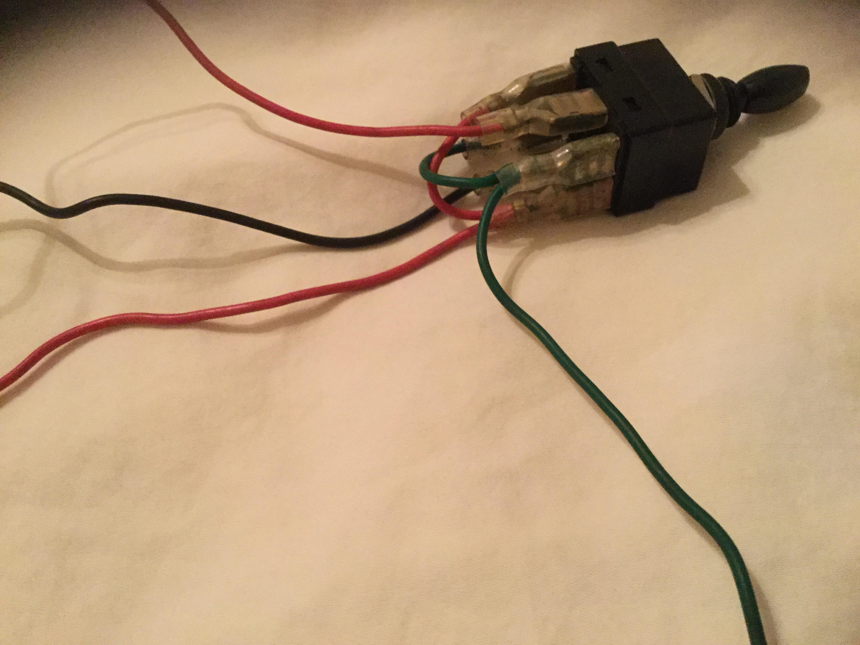
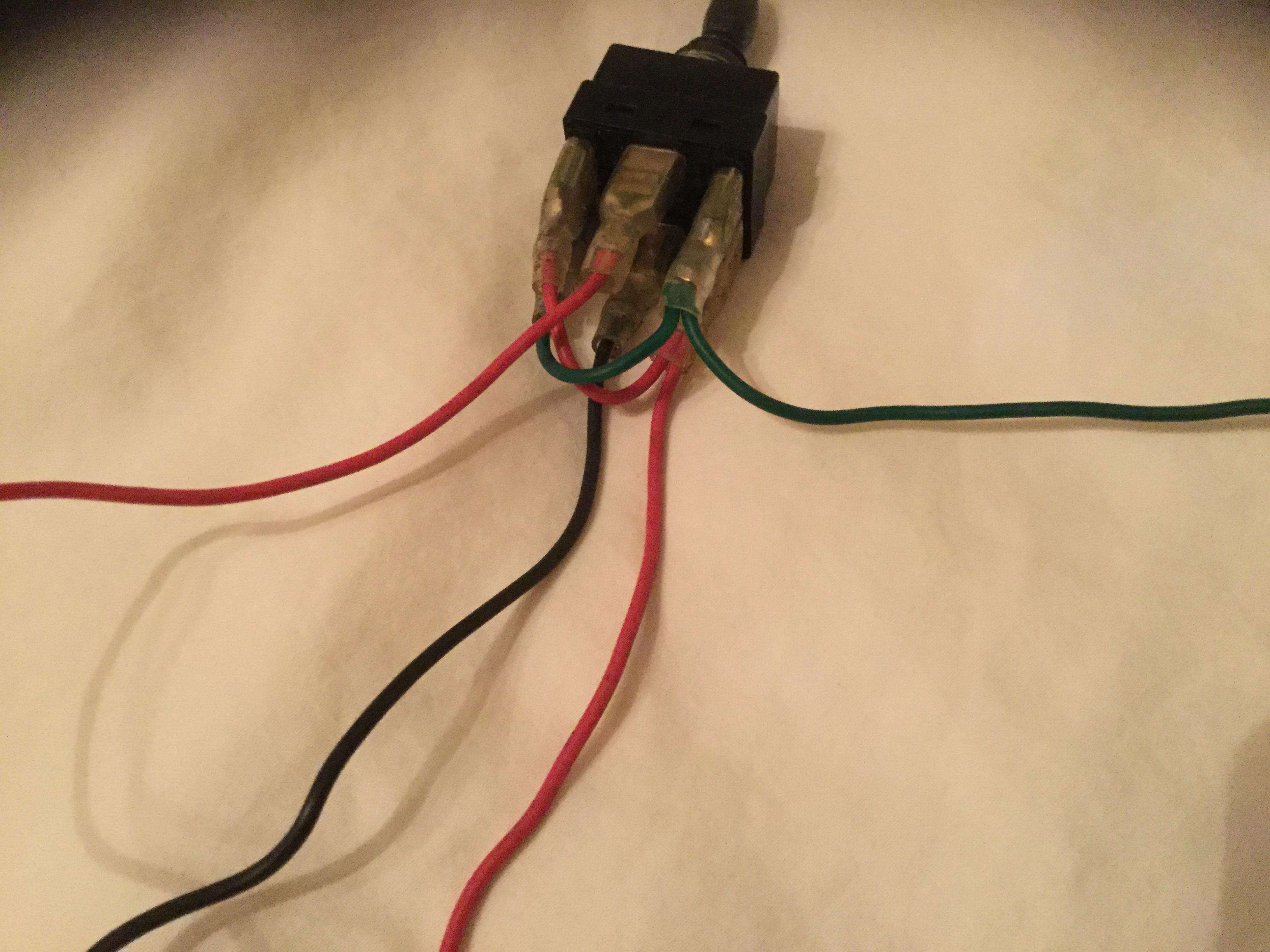
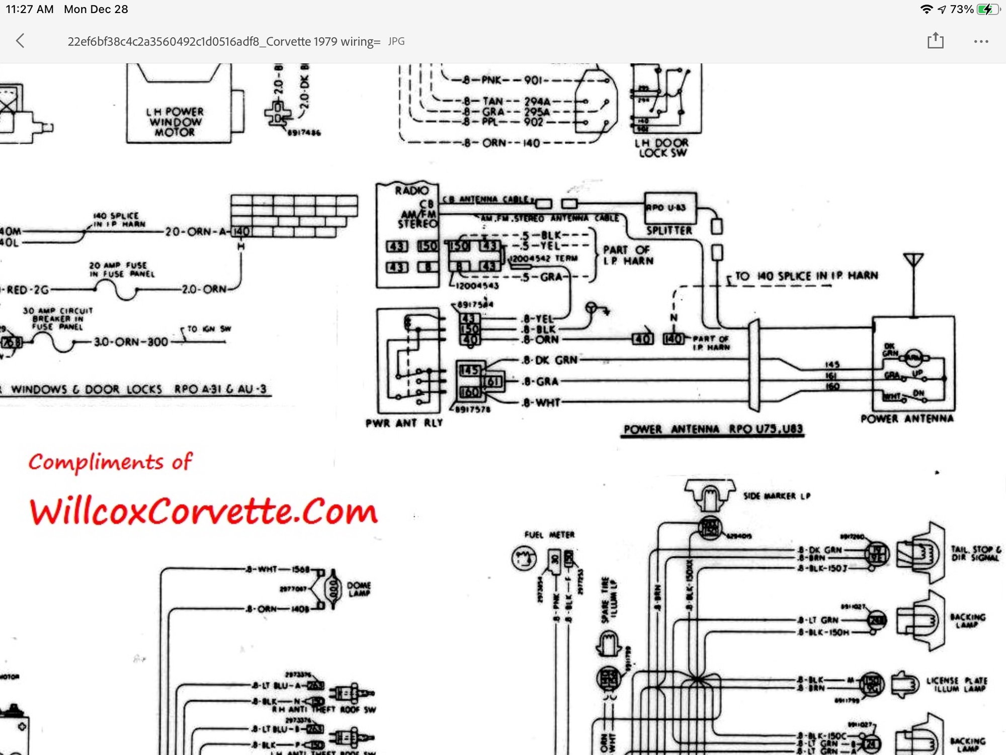
According to the 76 wiring diagram, the antenna has three power wires going to it. One is ground and the other 2 are +12v. The switch determines which one of the 2 are powered. One wire is for up, the other for down.
Car Power Antenna Wiring Diagram - wiring diagram is a simplified suitable pictorial representation of an electrical circuit. It shows the components of the circuit as simplified shapes, and the skill and signal connections amongst the devices. A wiring diagram usually gives guidance more or less the relative face and concurrence of devices ...
Installation of an Electric or Powered Antenna is fairly simple, you just need to ensure you have adequate space under the wing for the motor body of the antenna (or use the PA-02 remote motor antenna). You will also need to run power to the antenna along with the coaxial lead. Wiring the antenna is simple, there is a constant (+12v) feed ...
here this diagram electric for power anten with 2 wires or 3 wires as the riviera. there are 2 relays. on the new power antenna (as you can buy on the internet) you just have to find the 2 wires that feed the motor of the new power antenna + and - and you don't use the wire of autoradio signal.











0 Response to "45 power antenna wiring diagram"
Post a Comment