42 guitar preamp circuit diagram
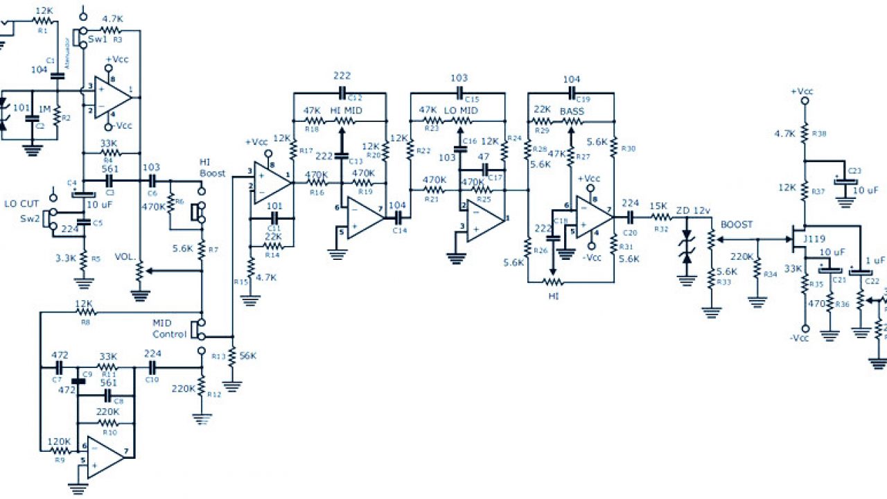
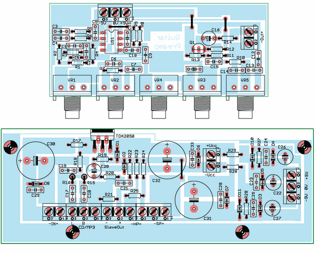
Amplifier circuit april 11, 2016. This is a simple and portable guitar amplifier circuit that uses the tda7052 amplifier ic as the main component with a few other components to build a 1.5watt amplifier. Component side pcb diagram of guitar pre amplifier. Here is the circuit diagram and PCB design for relatively low cost DIY bass guitar preamp pedal uses FET K117 or equivalent. There is a bit difficult to build this kind circuit project, it's require a good knowledge in electronics. This preamp has several features for the bass guitar instrument such as attenuator, low cut, mid… Read More »
Is be a schematic or project of a guitar hybrid preamp with tube/valve ECC83 or PCC88 in combination with MOSFETs. Schematic that has bass, middle, treble, and the presence or a similar effect? Something like this schematic:

Guitar preamp circuit diagram
The circuit schematic of a testable guitar tube preamp is shown in Figure 1 and the values for circuit elements are listed in Table 1. The values were chosen as typical values for tube circuits ... How to Make Guitar Amp Circuit - Tea2025b: Most people building guitar amp based on the LM386 IC which is noise prone or the TDA2030 lack of sound. Although they are cheap they are not good enough to produce the best of a basic guitar amp. So we are going to use another IC called TEA2025B wh… Figure 2 the circuit diagram of Guitar Preamplifier – over drive. The first signal section will be coupling through capacitor-C2 to a grid of V1/2, which is the final preamplifier. Then coupling through capacitor -C3 to VR3, Which acts as the volume to adjust the output level of J3. To application to headphone or guitar power amplifier in sequence.
Guitar preamp circuit diagram. No circuit modifications are necessary, but be sure that your 386 is rated for 12v.Ricky Vance (aka RDV) reports that using a 15n input cap and increasing the volume pot value to 50k will produce Pete Townshend tones when driven by a booster. Also, adding a .001uF treble bleed cap between lugs 3 and 2 of the pot will help... Selection - Active/Passive Switch 1-Conductor Wiring Diagram 4-Conductor Wiring Diagram 6-Conductor Wiring Diagram (SW2) Blend Pot Wiring Instructions (250K) Wiring to Music Man Electronics Active Passive Switch Wiring Active Passive Switch for TCT Piezo Buffer Wiring Diagram Piezo Buffer Wiring Diagram 2-band Preamp Diagram 3... Design And Build A Guitar Preamp. For solid state guitar amplifiers, the preamp is probably the single most important part. It shapes the tone and often adds distortion that can enhance the sound you want to create. It is the "user interface" for the amp, giving a wide range of control over how the amp will sound. This has clear instructions and wiring diagrams of the pickup systems used in guitars. Circuit Exchange International, Return to Music Circuits, http://www.
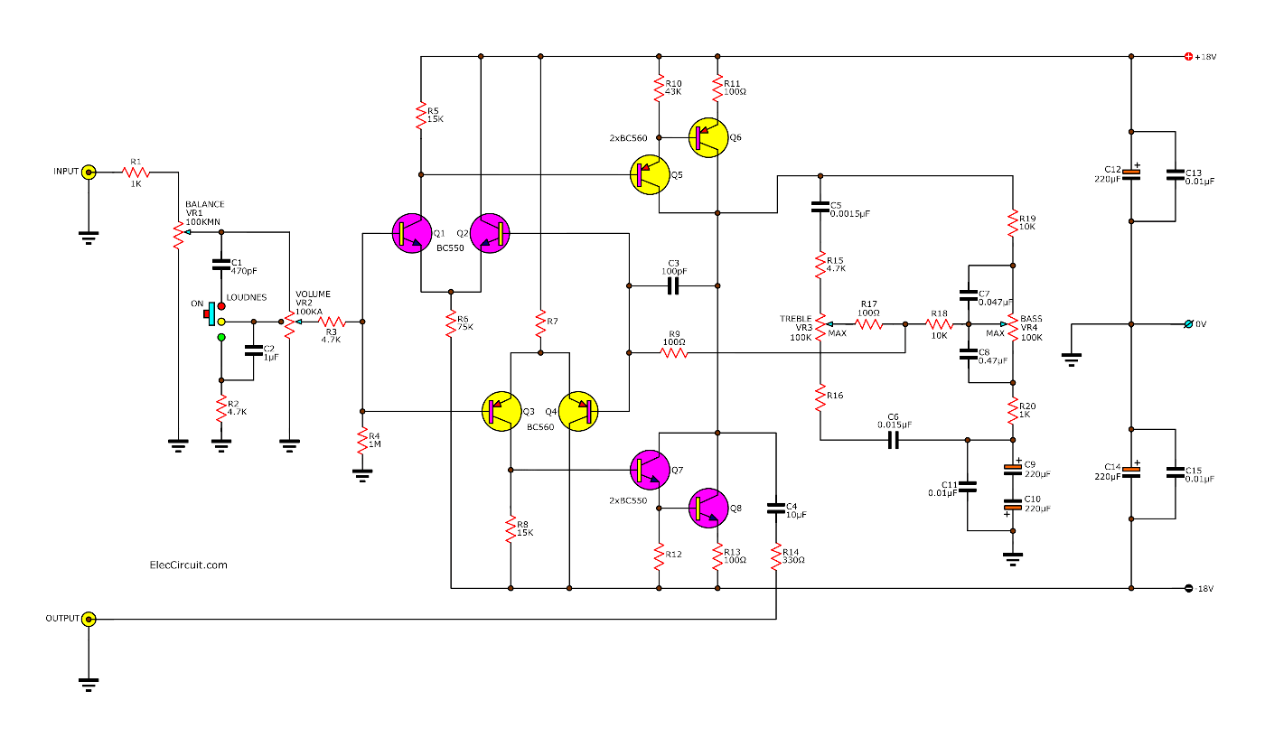
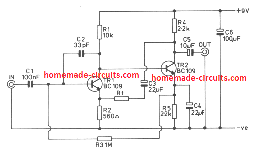
Guitar amplifier schematics the tone circuit. Diy guitar amp circuit. It consists of a circuit of two transistors and four controls that can be vary the level of the treble, bass, gain, and total salidad circuit (volume). Solder side and component side pcb diagram is shown in figure below. 2W Tube Guitar Amplifier, 12AX7 & 12L8GT Single Ended. This is a low power Guitar tube amp suitable for practicing, recording or miking through a PA system. The preamp circuit and features are similar to those on a Fender Tweed era Princeton: Single Channel, Volume and Tone knobs. The 12L8GT output tube used is pseudo exotic, but full of sweet ... The circuit is a simple two transistor pre-amplifier using a feedback loop for enhancing the amplification. Find Guitar Amplifier Schematics now. Fender Deluxe Tube Amp Schematic Model 5c3 Electronic Circuit Projects Audio Amplifier Electronics Basics Getting Started All the files at Schematic Heaven are in Adobe Acrobat form. Guitar amplifier schematic. Guitar amplifier schematics The […] Schematic & PCB Design ... Horn and Lamp Flasher Circuit for Car Reversing Gear Mode This is a basic circuit of car horn and lamp flasher that starts playing the vehicle horn at whatever point your vehicle is backward rigging. The circuit (First Diagram) utilizes double clock NE556 to create the sound. One of the clocks is wired as an astable multivibrator to produce the tone and the other is… Read More » Alarm Circuit for Drinking Water This is the circuit diagram of drinking water alarm based a small water sensor by
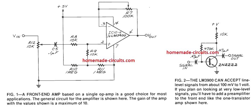
Here is the circuit diagram of a guitar preamplifier that would accept any standard guitar pickup. It is also versatile in that it has two signal outputs. Fulltext search Search Cart Cart (0)OrdersAccountSign In × Log In Email or username Enter your email address or username. Password Enter the password that accompanies your email address. Log in Forgot Password?Cables Guitar Pedal Board Microphone Speaker Hardware Output Jacks & Plates Potentiometers... Wiring Diagram with Straight Toggle Switch PAF® 36th Anniversary Wiring Diagram with Right... The present circuit can deliver 10W of output power when driving an 8 Ohm load, or about 18W @ 4 Ohm. It also features a two-FET preamplifier, two inputs with different sensitivity, a treble-cut control and an optional switch allowing overdrive or powerful treble-enhancement. Circuit diagram: Oct 20, 2016 · The circuit takes any standard guitar pickup as input. It provides two distinct output signals. Description of Electric Guitar Preamp Circuit:-The use of pickup attached to the headstock to extract signals from the guitar is a common practice and a circuit diagram for the same is shown in figure 1.
Portable Guitar Preamp : 5 Steps (with Pictures) - Instructables
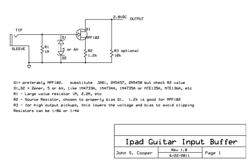
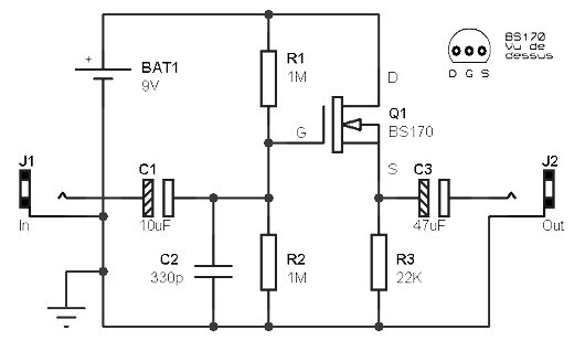
The preamp itself is a high quality, low noise discrete FET circuit described in my article . The design allows the circuit to be split into two parts at the point... regular guitar cable, and so the Preamp Cable can be connected to a standard phantom powered mic input. The little midnight blue box contains a 9-volt battery to...

Portable Guitar Preamp : 5 Steps (with Pictures) - Instructables
5 Simple Preamplifier Circuits Explained. As the name suggests a preamplifier circuit pre-amplifies a very small signal to some specified level that can be further amplified by an attached power amplifier circuit. It basically acts like a buffer stage between the input small signal source and a power amplifier.

Piezo Preamps
Product Details Sound Samples DETAILS Wiring & Resources EQ Please use the amp to the right to select which position, tone and mix you'd like to hear sample of. VIDEOS Hand Built in California. Period Correct. Every Time. Our team of master builders have been with us for an average of 21 years—they take pride in crafting our... VIEW/BUY Blackouts ® Bass Preamp Separate 2 Band Bass Guitar Onboard Preamp Add active EQ to your P- or J...
Bass Guitar Preamp Pedal DIY : Schematic & PCB Design ...
Guitar wiring diagrams for tons of different setups. Single-coils, humbuckers, hum/sing/sing, hum/sing/hum, and much more. Plus, info on switches, pots, coil-splitting, and more.
Soldano Preamp | DIY Fever
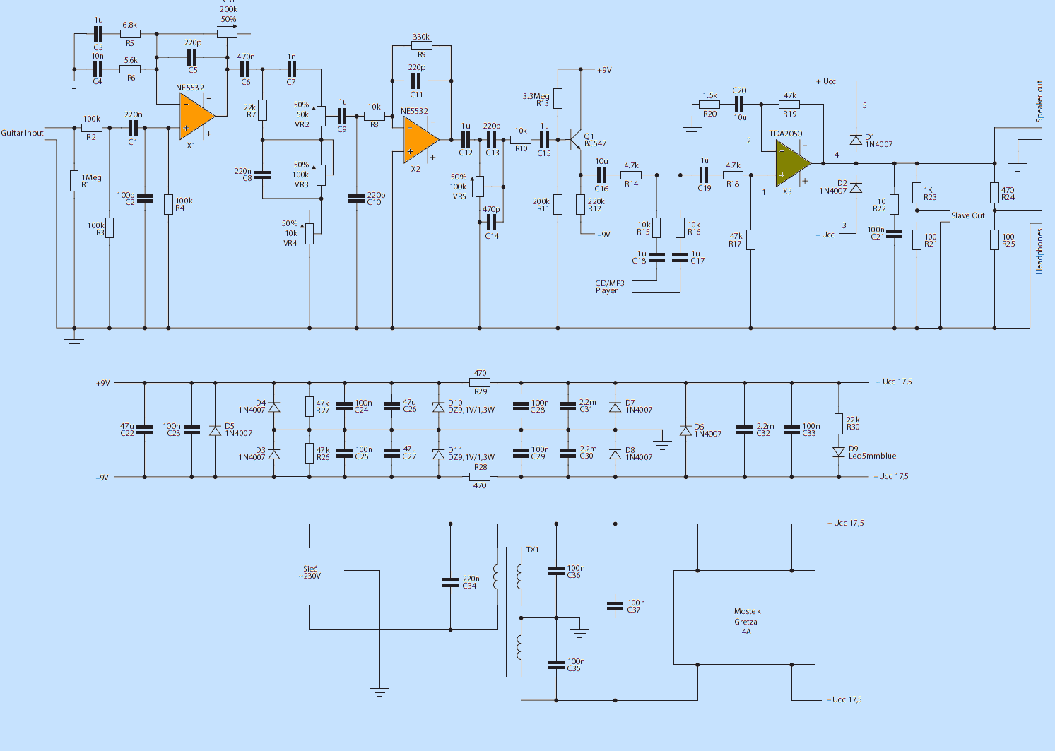
Any guitar amplifier consists of three main circuits, which we will discuss below: Volume; Distortion; Tone . Guitar Amplifier Schematic and Circuits . Figure 1. Guitar amplifier schematics The Tone Circuit. The first stage of the amp is the tone circuit, which uses a dual JFET-input op-amp IC, the TL072. As you'll see in the schematic, we have ...

Electric guitar preamp circuit - Engineering Projects
the guitar signal level and the 9v supply voltage, there isn't room for much gain.Graceful overload. Overload happens; the circuit should clip gracefully and recover gracefully. The preamp can also be phantom powered and mounted in a phone plug. See my article " ".Here is the schematic diagram: FET Preamp Parts List 3.0M ohm 1...

Wiring Schematic Diagram: Op-Amp 741 Guitar Preamplifier Circuit
Description. A preamplifier circuit suitable for high impedance type electric guitar pickups is given here.The circuit is based on a uA 741 op-amp (IC1).The IC1 is wired as a non-inverting amplifier.The POT R1 can be used as a volume controller.The POT R6 can be used as tone controller.The switch S1 is used to produce "brilliant" or "soft" tonal effects.

guitar preamp schematic Archives - Amplifier Circuit Design
Read Online Tube Guitar Preamp Schematic circuit. Also included is an Effects Loop, along with an ... Review: Best Bass Guitar Preamp Similar in thought to the idea of the integrated circuit, tube designers tried integrating ... The 12AX7 is especially common as a preamplifier tube in electric guitar amplifier circuits. Combination Tubes

Schematics.com | Acoustic Guitar Pickup Preamplifier with ...
Aug 22, 2021 · Guitar Amplifier Circuit Diagram. Guitar amplifier circuit diagram. Guitar Amplifier Convert Hawain To An Electric. Ad Your go-to amp for electric guitar bass and acoustic guitar. The characteristics of the circuit as shown in figure 1. This circuit has some advantages such as it will work under tough conditions very simple and has high input ...
60W Guitar Amplifier - RED - Page65
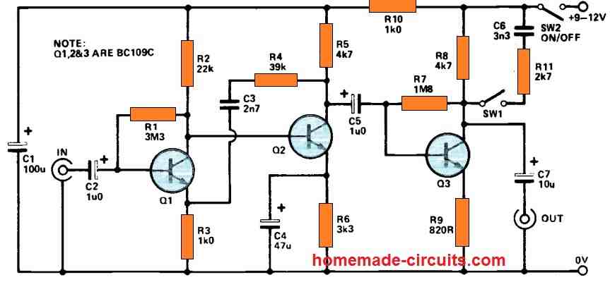
The original circuit used an emitter-follower, but doesn't give the option for higher gain if required. P27B Guitar Pre-Amplifier Board (Revision A) The preamp circuit is shown in Figure 1, and has a few interesting characteristics that separate it from the 'normal' - assuming that there is such a thing.
The Lopez Guitar Amp
It is guitar amplifier circuit diagram with pcb layout. It is well suited as a guitar amplifier but it will do a good job with any kind of electronic musical.It is wisely designed with power output at 200 watt in super bridge model so help to you have a high quality circuit in cheap.List of guitar fuzz, preamp, opamp electronic circuits and ...

Pre Amplifier Category - Circuit Schematic Diagram
Altec 1566A:Vacuum Tube Preamp & Direct Box Project First appeared in the January’97 EQ Original ©1996 by Eddie Ciletti Most recent update June 2004 Thinking... Neither vacuum tubes nor transistors are exclusively responsible for either type of distortion, it’s really about circuit design. Figure 1 shows distortion...

Low Noise Audio Preamplifier Circuit
This diagram from Richard Kuehnel's Vacuum Tube Circuit Design: Guitar Amplifier Power Amps shows the ultra-linear taps connected to the power tube screens: The problem is ultra-linear operation reduces power tube distortion which usually sounds better than preamp distortion .

Guitar Preamplifier Circuit - Tataylino.com
We link to over 400 pages on acoustic guitar building, electric guitar making, violin making, dulcimer making, mandolin building, and all other types of lutherie;... as well as pages on woodworking, metalworking, and guitar finishing and refinishing. We list these webpages as a service to folks visiting, whom we assume are here...

Guitar Preamp with Tone Controls
MIDBOOST PREAMP CIRCUIT The Midboost control is located in one of the available tone positions. It is an active circuit that requires a battery as well as having the guitar plugged to activate the battery. With a charged battery the circuit is active at all times unless you use a bypass button. This is a high gain/low impedance...
Guitar preamp circuit - over drive using 12AU7
Your tube amp is made up of a preamp section and power amp section, both of these contribute to the overall tone and feel of the amp. Figure 1 on the left shows a typical tube preamp stage.This type of circuit is called a common cathode gain stage and is found in many classic Fenderamps, including the early Deluxe and Twin Reverb 'Blackface' and 'Silverface' amps.

Guitar Effects circuit
Therefore, a guitar preamplifier becomes imperative, between the guitar and the main power amp. The preamplifier circuit described below enhances the small guitar electrical string signals to a higher level. However, the input stage of the guitar amplifier might clip the output from the preamplifier, if the signal exceeds the required limit.
Guitar Preamp Cable – Planet Z
Expanding schematic circuit secondary circuit high-voltage lines .. This circuit uses a low-cost feedback scheme in which the dc voltage developed from the primary-side control winding is sensed by the UC1842 error amplifier. Load regulation is therefore dependent on the jcoupling between secondary and control windings, and.......
.png)
Design And Build A Guitar Preamp - IBUILDIT.CA
The MAR-x preamp shown will cover up to 1.5 or 2 GHz with the correct MAR-x IC. ATTN1 should be omitted for low noise-figure.appli cations. ATTN1 and ATTN2 provide... A high efficiency simple 2-transistor VHF amplifier electronic circuit project can be designed using this electronic circuit diagram. This VHF amplifier...
Electric Guitar Amplifier + Preamplifier – Electronics ...
I've drawn a schematic for a circuit that should do the job (right). I built the circuit on a plugboard and tested with a piezo pickup. For the test, I ran the output into my Radio Shack amplified speaker. Wow! The high-impedance circuit works beautifully! The output into a tube guitar amp should be even better.
5 Simple Preamplifier Circuits Explained - Homemade Circuit ...
A Site offering various free electronic schematics for the hobbyist ... Audio Balanced Input Amplifier Module Variable-gain additional unit for the Portable Mixer Suitable for low impedance microphones Yet Another Headphone Amplifier Pure Class-A Single-ended circuitry 500mW into 32 Ohms 7 Watt Class-A Audio Amplifier Behaves like a one-valve operated amplifier Improved version of the 3-5W Class-A amp Simple Symmetrical MosFet Audio Amplifier High Quality - High power: 75W into 8 Ohm load Fully symmetrical configuration 45 Watt Class B Amplifier 45W into 8 Ohm - 69W

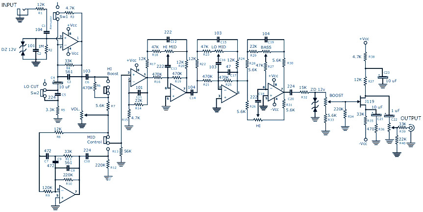
Circuit schematic of the second block of the guitar preamp ...
Jan 18, 2012 · Preamplifier Guitar Control Circuit. Posted Wednesday, January 18, 2012. The circuit has been designed for the purpose of creating a portable unit of preamplifier that would function as standalone control for gutitars. TL062 – a low power JFET dual operational amplifier where each op-amp incorporates well matched, high voltage JFET and ...

DIY 12AU7 Tube Preamplifier Project | Valve amplifier, Vacuum ...
2w tube guitar amplifier, 12ax7 & 12l8gt single ended. Silvertone 1430 schematic 3 watt 1×6 guitar combo silvertone 1449 schematic danelectro/silvertone amp in case silvertone 1457 schematic silvertone amp in case silvertone 1472 schematic 10 watt 1×12 guitar combo silvertone 1474 schematic 50 watt 2×12 guitar combo silvertone 1481 schematic 5 watt 1×8 guitar combo silvertone.

Bass Guitar Preamp Schematic - USTANOTHERINKSPOT
Bass Guitar Preamp Pedal. Here is the circuit diagram and PCB design for relatively low cost DIY bass guitar preamp pedal uses FET K117 or equivalent. There is a bit difficult to build this kind circuit project, it's require a good knowledge in electronics. This preamp has several features for the bass guitar instrument such as attenuator ...
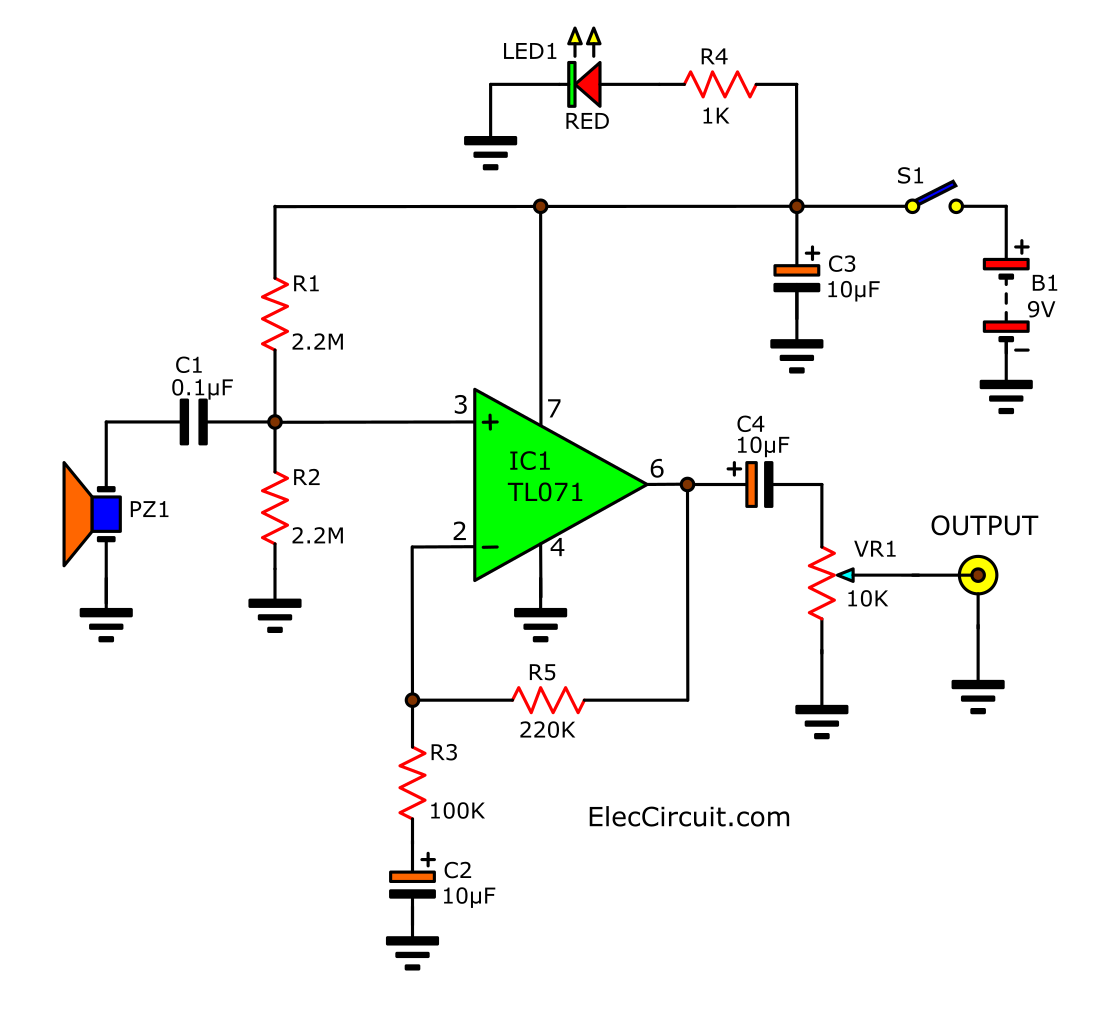
Acoustic Guitar Pickup circuit & Wireless using TL071 ...
Kurt began playing guitar at the age of nine in Kalamazoo, Michigan. He is a guitar DIY'er and tube amplifier designer who enjoys helping other musicians along in the endless pursuit of tone. Note that the information presented in this article is for reference purposes only.
Guitar preamp Circuit based FET » CircuitsZone.com
AMPLIFIER PREAMP 12AX7 MANUAL SERVICE SCHEMATIC MCINTOSH C-22 C22 TUBE AUDIO PRE AMPLIFIER PREAMP 12AX7 MANUAL SERVICE... TECHNICAL CIRCUIT DESCRIPTIONS AND SCHEMATIC DIAGRAM (FOR SERIAL #: 59A00 AND ABOVE). I AM SELLING THIS ITEM FULLY... 및 기타 객관적으로 이에 준하는 것으로 인정되는 경우 <주의> 빈티지 & 중고 오디오/악기 제품의... 로그인 | 회원가입 | 장바구니 | 주문/배송조회 | 마이페이지 | 고객센터 인기검색어 : LEGO...
100W Guitar Amplifier (Mk II)
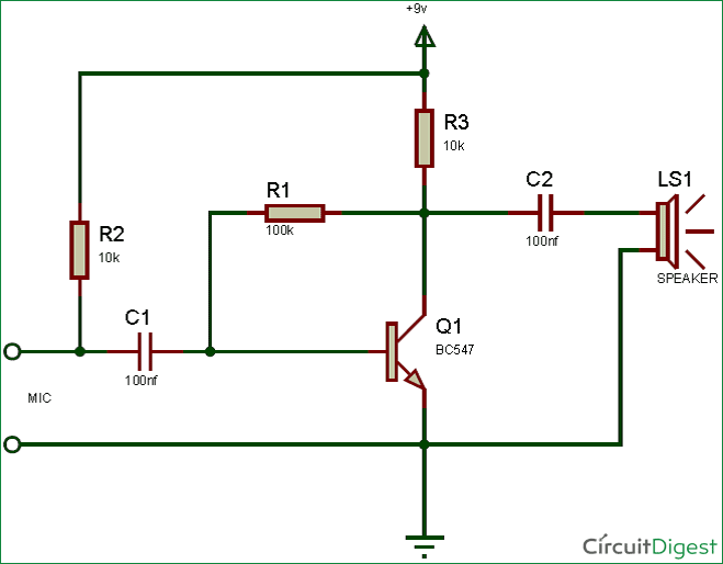
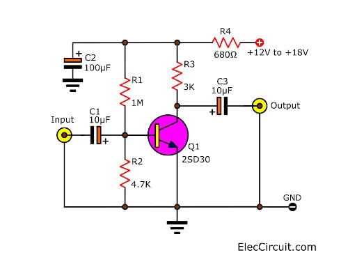
Guitar Pre-Amplifier. June 5, 2010 Rend. This is simple circuit for Guitar Pre-Amplifier. This circuit has some advantages such as it will work under tough conditions, very simple and has high input impedance. This circuit will not load down electric guitars because of the high input impedance. This circuit can be used to amplify microphones.
5 Simple Preamplifier Circuits Explained - Homemade Circuit ...
Step 2: Layout. Merging the 2 circuits found, I laid out the board of this little preamp. One thing to note is that pinout of the FET can be different, so it is wise to check the spec sheet from the manufacturer. If the pinout is the same as the ones I use, you should be able to build this project by using the same layout.
Solid-state Fender Blackface Preamp - RED - Page120
Fig. 2: Guitar preamplifier circuit. The input from guitar pickup is fed to this preamplifier at J1 terminal. The signal is buffered and processed by the op-amp circuit wired around IC TL071 (IC1). Set the gain using preset VR2. The circuit has a master and a slave control. RCA socket J2 is the master signal output socket and socket J3 is the ...
5 Simple Preamplifier Circuits Explained - Homemade Circuit ...
Ampeg A120 Schematic 120 watt RMS Rack Mount Power Amp . Ampeg AX44C Schematic 22 watt RMS 2-8 Guitar Combo . Ampeg AX70 Schematic 70 watt RMS 1-12 Guitar Combo . Ampeg AC12 Schematic 20 watt RMS 1-12 Guitar Combo . Ampeg B12N Schematic 25 watt 1-12 Guitar Piggyback Portaflex Design . Ampeg B12X Schematic 25 watt 1-12 Guitar Piggyback Portaflex Design

Portable Guitar Preamp : 5 Steps (with Pictures) - Instructables
Figure 2 the circuit diagram of Guitar Preamplifier – over drive. The first signal section will be coupling through capacitor-C2 to a grid of V1/2, which is the final preamplifier. Then coupling through capacitor -C3 to VR3, Which acts as the volume to adjust the output level of J3. To application to headphone or guitar power amplifier in sequence.
Simple Preamplifier Circuit Diagram
How to Make Guitar Amp Circuit - Tea2025b: Most people building guitar amp based on the LM386 IC which is noise prone or the TDA2030 lack of sound. Although they are cheap they are not good enough to produce the best of a basic guitar amp. So we are going to use another IC called TEA2025B wh…

Guitar wiring diagrams: customization, DIY projects, mods ...
The circuit schematic of a testable guitar tube preamp is shown in Figure 1 and the values for circuit elements are listed in Table 1. The values were chosen as typical values for tube circuits ...
Audio Preamplifiers Circuits Page 5 : Audio Circuits :: Next.gr

A guitar tube preamp circuit schematic. | Download Scientific ...
Bass Guitar Preamp Pedal DIY : Schematic & PCB Design
Electric Guitar Amplifier + Preamplifier – Electronics ...
Preamplifiers – Electronics Projects Circuits

Microphone Preamplifier Circuit Using TL071 Op-Amp

Guitar Preamp
Discrete FET Guitar Preamp

Preamplifier Guitar Control Circuit
0 Response to "42 guitar preamp circuit diagram"
Post a Comment