44 entity relationship diagram normalization
Database administrators and software developers use Entity Relationship Diagrams to organize a database's design. The diagram specifies major groups of information and specific attributes such as name, telephone number and address. Sometimes, data in a major group comes in multiples; for example, a sales order may have one line item, five or 20. Browse other questions tagged many-to-many normalization entity-relationship ternary er-diagrams or ask your own question. The Overflow Blog Plan for tradeoffs: You can't optimize all software quality attributes
Normalization to create a single source of truth and maintain data integrity Constructing an entity-relationship diagram (ERD) that clearly represents the following types of relationships: One-to-one One-to-many/many-to-one Many-to-many Standardization to allow templated analytics products to be built on top of schemas
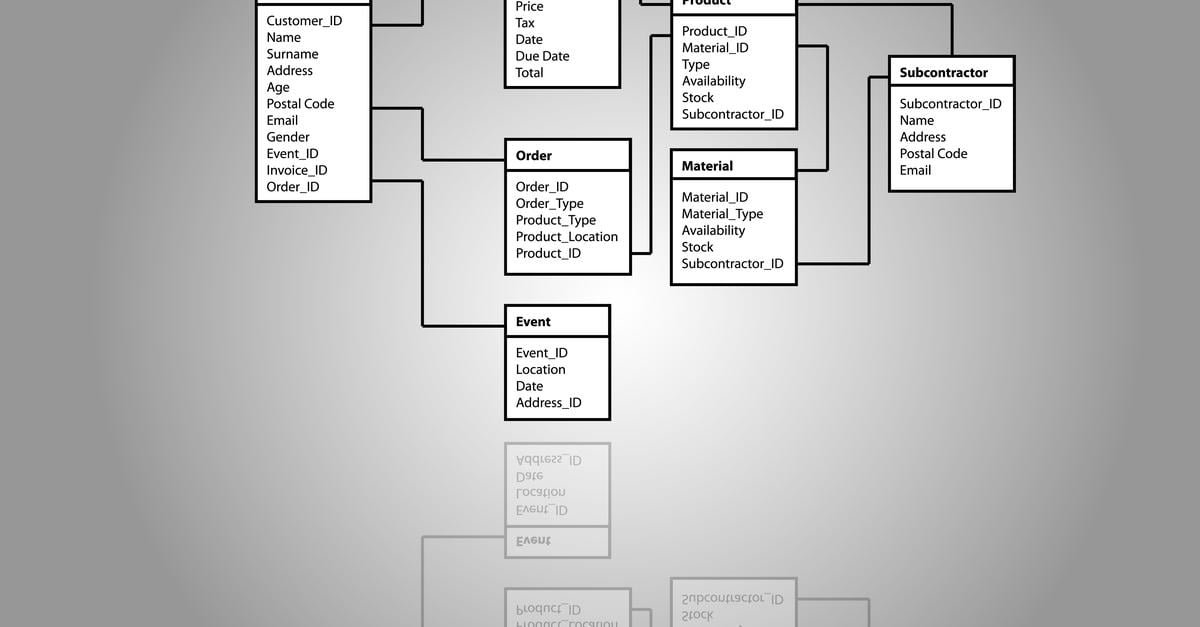
Entity relationship diagram normalization
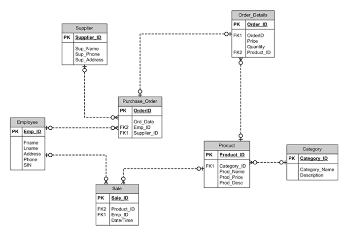
Er Diagram Normalization Normal Forms March 31, 2020 · Diagram Er Diagram Normalization Normal Forms - Entity Relationship is actually a higher-levels conceptual information version diagram. Entity-Connection design is dependant on the notion of genuine-planet entities as well as the relationship between the two. Each entity in the ER Diagram becomes a relation. A properly normalized ER diagram will indicate where intersection relations for many-to-manymappings are needed. Relationships are indicated by common columns (or domains) in tables that are related. We will examine the tables for the Acme Widget Company derived from the ER diagram Employee 8.12.2021 · Entity Relationship Diagram by Mike Chapple as published on the About.com website. Join over thousands of organizations that use Creately to brainstorm, plan, analyze, and execute their projects successfully. Get started here. Entity relationship diagrams ER diagram symbols ER diagram tutorial ER diagrams.
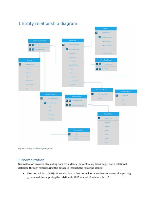
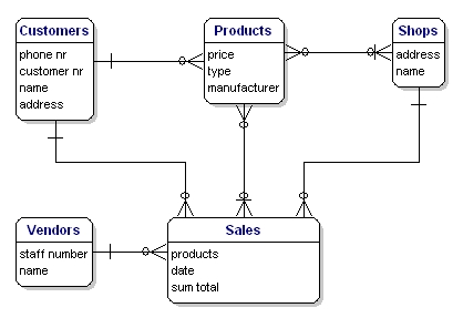
Entity relationship diagram normalization. 1.1.3 Entity Relationship Diagram (ERD) ... We need to make the content of each table is only related to its own entity. Therefore the normalization process should be implemented. The first step is transforming the un-nornalized form table into first normal form. The definition of first normal form is 'all non-key attributes in relation is if ... Entity-Relationship (ER) Diagrams 29 STUDENT DEPT MINOR_D FACULTY TUTORS CHAIR_F MAJOR_D Tutor Tutee 1 1 N M N M All departments have a faculty member who serves as the chair. A faculty member can only chair one department. N 1. CS3200 -Database Design Spring 2018 Derbinsky Structural Constraints Using the Entity-Relationship Diagram to Determine Record Keys. The E-R diagram can be used to select the keys that a document or database relationship needs. Building the E-R diagram and printing an outstanding (basic) key for each data substance is the underlying development. The figure below provides an E-R overview for a consumer demand system. Entity Relationship Diagram, also known as ERD, ER Diagram or ER model, is a type of structural diagram for use in database design. An ERD contains different symbols and connectors that visualize two important information: The major entities within the system scope , and the inter-relationships among these entities .
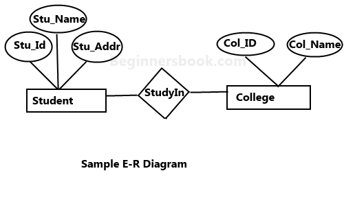
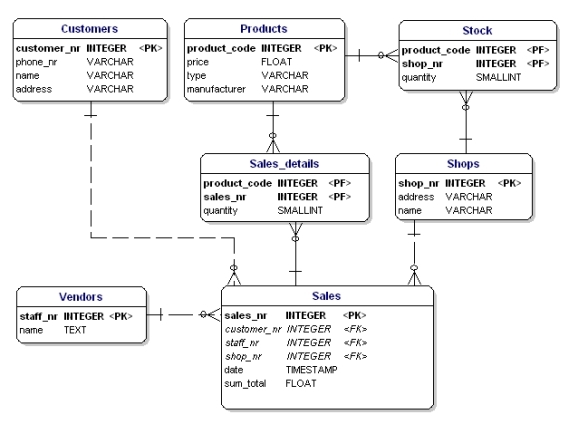
logic data modeling entity relationship diagrams part. Normalization Diagram. Here are a number of highest rated Normalization Diagram pictures upon internet. We identified it from honorable source. Its submitted by government in the best field. We take on this nice of Normalization Diagram graphic could possibly be the most trending subject ... An Entity–relationship model (ER model) describes the structure of a database with the help of a diagram, which is known as Entity Relationship Diagram (ER Diagram). An ER model is a design or blueprint of a database that can later be implemented as a database. The main components of E-R model are: entity set and relationship set. Now, the data satisfy the requirements of third normal form and do not contain more than one independent multi-valued fact about an entity which makes it to meet requirements of fourth normal form. Here is the ER-diagram that I got as a result in fourth normal form. Normalization for the entire Entity Relationship Diagram Now you should review all entities and relationships in the diagram for your online store and modify them as needed to achieve 3NF. Your resulting diagram should be similar to this one: Normalized entity-relationship diagram for our online store Conclusion
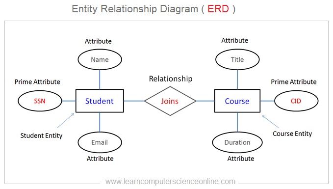
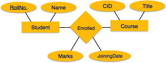
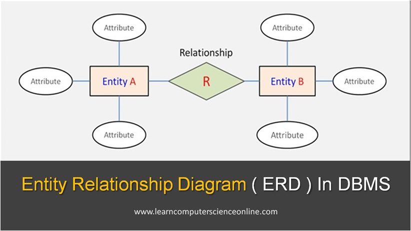
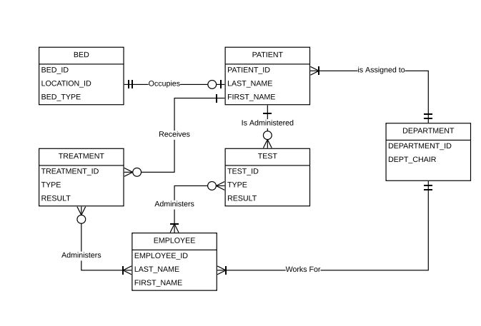
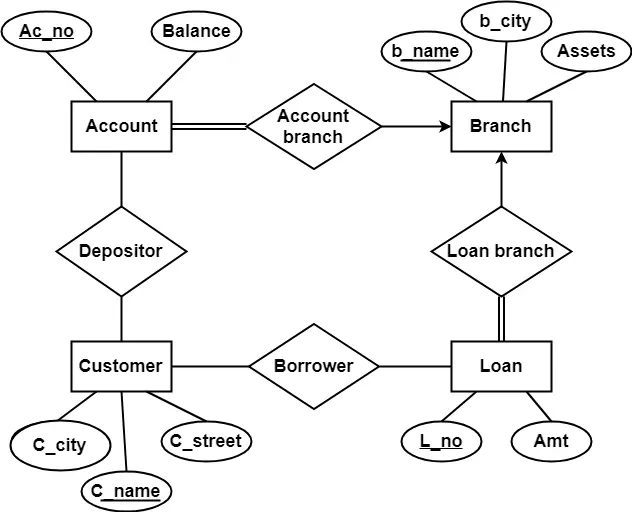
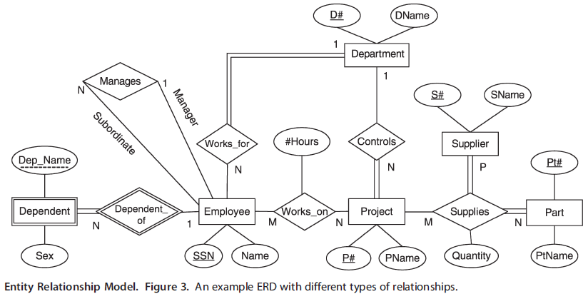
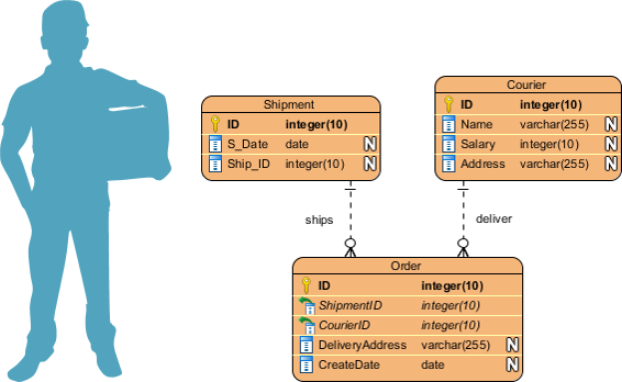
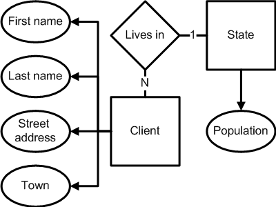
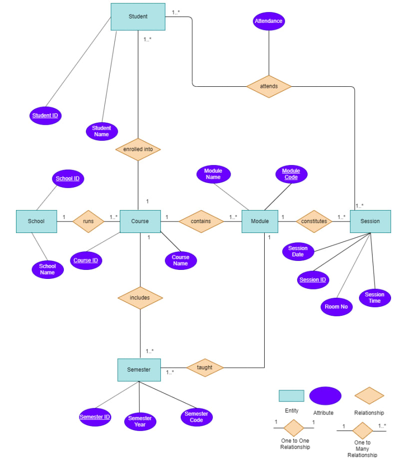
What is an Entity Relationship Diagram (ERD)? An entity relationship diagram (ERD) shows the relationships of entity sets stored in a database. An entity in this context is an object, a component of data. An entity set is a collection of similar entities. These entities can have attributes that define its properties. Another term to know is entity type which defines a collection of similar entities. An entity set is a collection of entities of an entity type at a particular point of time. In an entity relationship diagram (ERD), an entity type is represented by a name in a box. For example, in Figure 8.1, the entity type is EMPLOYEE. Figure 8.1. ERD, or Entity Relationship Diagram, is, as the name implies, a type of diagram used to show the logical entries (typically tables) and relationships between them in a database. Note that you can create an ERD for a horrible database design. Normalization is a process that helps create good database design. Entity Relationship Diagram Examples Crow's Foot and Chen's notation examples. Creating the entity-relationship (ER) model by visually representing the structure of some database, mainly the business one, which data equates to its entities (or objects) that are connected by relationships showing requirements and dependencies, you need proper software to provide you with the symbols necessary ...
We also implemented those design changes in our entity-relationship diagram in LucidChart. In this article, you will generate the SQL commands for implementing your database in PostgreSQL, directly from LucidChart. This article is a short one since you already completed most of the hard work by creating a normalized database design. Let's get ...
An Entity Relationship Diagram (ERD) is a type of diagram that lets you see how different entities (e.g. people, customers, or other objects) relate to each other in an application or a database. They are created when a new system is being designed so that the development team can understand how to structure the database.
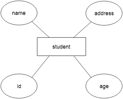
Attributes are the descriptive properties which are owned by each entity of an Entity Set. There exist a specific domain or set of values for each attribute from where the attribute can take its values. Types of Attributes- In ER diagram, attributes associated with an entity set may be of the following types- Simple attributes; Composite attributes
entity-relationship diagram: Normalization Theory (Chapter 7) Formalize what designs are bad, and test for them. Outline of the ER Model. ER model -- Database Modeling. The ER data mode was developed to facilitate database design by allowing specification of an . enterprise schema .
logical design: mapping to a relational model each entity in the er diagram becomes a relation. a properly normalized er diagram will indicate where intersection relations for many-to-many mappings are needed. relationships are indicated by common columns (or domains) in tables that are related. we will examine the tables for the diveshop …
Nov 06, 2020 · ER Diagram Example – 2. In this ER diagram, Products, trainers are the strong entities and the Parts entity is a weak entity. Because Parts entity depends on Products entity on a relationship of Belongs to for its existence.
October 10, 2019 · Diagram Er Diagram Normalization - ER is really a high-stage conceptual info version diagram. Entity-Relation model will depend on the notion of actual-entire world entities and the relationship between them. ER modeling really helps to examine info requirements systematically to generate a nicely-made data base.
The enhanced entity–relationship (EER) model (or extended entity–relationship model) in computer science is a high-level or conceptual data model incorporating extensions to the original entity–relationship (ER) model, used in the design of databases.
Entity-Relationship Diagram views real world as entities. It introduced in 1976 by P.P.Chen and is known as ER Diagram, E R Model, etc. The following states the importance of Entity-Relationship diagram − Assist the Database Developer The ER Diagram assists the design even before the construction of tables begins. Requirements Gathering
Sep 27, 2021 · An Entity Relationship Diagram (ER Diagram) pictorially explains the relationship between entities to be stored in a database. Fundamentally, the ER Diagram is a structural design of the database. It acts as a framework created with specialized symbols for the purpose of defining the relationship between the database entities.
18.12.2021 · Entity Relationship Diagram (ER Diagram) is a graphical approach to database design. It uses Entity/Relationship to represent real world objects.
What is Entity Relationship Diagram (ER-Diagram)? ER-Diagram is a pictorial representation of data that describes how data is communicated and related to each other. Any object, such as entities, attributes of an entity, sets of relationship, and other attributes of relationship, can be characterized with the help of the ER diagram.
Normalization in DBMS can be a hard topic to understand. See step-by-step instructions about database normalization and an example in this article
A conceptual or logical data model, as represented by an entity relationship diagram, is suited to model the data, regardless of what anyone decides to call the collections of data points. In other words, relational has nothing to do with it.
DBMS - Data Schemas, A database schema is the skeleton structure that represents the logical view of the entire database. It defines how the data is organized and how the relations
Unit-2 Entity-Relationship Diagram and Normalization (13 Marks) Source : Concepts of Database Management System Shefali Naik Introduction • An E-R model is the most popular semantic model. • The semantic model represents and explains the meaning of real world concepts which are implemented in that model.
Using the Entity-Relationship Diagram to Determine Record Keys The E-R diagram may be used to determine the keys required for a record or a database relation. The first step is to construct the E-R diagram and label a unique (primary) key for each data entity. Figure below shows an E-R diagram for a customer order system.
Currently im trying to do an assignment question which is assigned to me which is asking me the normalization process. im aware of the 3 normal form. but im stuck with the 3rd normalisation form because i feel that im going to get the similar answer. if i did a mistake in my 1NF and 2NF please let me know. ... Entity Relationship diagram for a ...
10.6.2021 · A relationship between two entities of a similar entity type is called a recursive relationship. Here the same entity type participates more than once in a relationship type with a different role for each instance. In other words, a relationship has always been between occurrences in two different entities.
Normalization ERD Exercise ( Entity Relationship Diagram) Use Creately's easy online diagram editor to edit this diagram, collaborate with others and export results to multiple image formats. Defines the relationships of the Database -- You can edit this template on Creately's Visual Workspace to get started quickly.
"Thispresentation was prepared as part of the HAP 671 course on healthcare database taught by Farrokh Alemi, PhD atGeorge Mason University Department of Heal...
Entity relationship diagram (ERD) is one of the most widely used technique for data modeling. An ERD developed during the conceptual data modeling phase of the database development process is generally transformed and enhanced through normalization principles during the logical database design phase.
8.12.2021 · Entity Relationship Diagram by Mike Chapple as published on the About.com website. Join over thousands of organizations that use Creately to brainstorm, plan, analyze, and execute their projects successfully. Get started here. Entity relationship diagrams ER diagram symbols ER diagram tutorial ER diagrams.
Each entity in the ER Diagram becomes a relation. A properly normalized ER diagram will indicate where intersection relations for many-to-manymappings are needed. Relationships are indicated by common columns (or domains) in tables that are related. We will examine the tables for the Acme Widget Company derived from the ER diagram Employee
Er Diagram Normalization Normal Forms March 31, 2020 · Diagram Er Diagram Normalization Normal Forms - Entity Relationship is actually a higher-levels conceptual information version diagram. Entity-Connection design is dependant on the notion of genuine-planet entities as well as the relationship between the two.
















0 Response to "44 entity relationship diagram normalization"
Post a Comment