41 Phasor Diagram Of Rlc Circuit
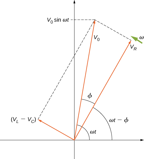
Series RLC Circuit Impedance Calculator • Electrical, RF ... The phasor diagram for a series RLC circuit for capacitive (left), inductive (center) and pure resistive (right) impedance. The voltage vectors on the diagram produce a rectangular voltage triangle with a hypotenuse V T , vertical leg V L -V C and horizontal leg V R . PDF Rlc Circuits Problems And Solutions Friendspetfest RLC Series circuit, phasor diagram with solved problem. An RLC series circuit contains all the three passive electrical components, Resistor Capacitor, and Inductor in series across an AC source. As there is only one path for current in a series combination, the
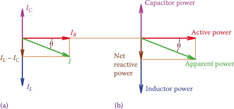
RLC Circuit Analysis (Series And Parallel) - Clearly ... Phasor diagram of parallel RLC circuit, I R is the current flowing in the resistor, R in amps. I C is the current flowing in the capacitor, C in amps. I L is the current flowing in the inductor, L in amps. I s is the supply current in amps. In the parallel RLC circuit, all the components are connected in parallel; so the voltage across each ...
Phasor diagram of rlc circuit
What is LC Circuit? Formula, Equitation & Diagram | Linquip Phasor Diagram for a Series RLC Circuit (Reference: electronics-tutorials.ws) Analysis of LCR Circuit, Phasor diagram and FAQs - BYJUS An LCR circuit, also known as a resonant circuit, tuned circuit, or an RLC circuit, is an electrical circuit consisting of an inductor (L), capacitor (C) and resistor (R) connected in series or parallel. The LCR circuit analysis can be understood better in terms of phasors. A phasor is a rotating quantity. Current Vs Voltage Graph. Phasor Diagram of Series RLC Circuit - YouTube Network Theory: Phasor Diagram of Series RLC Circuit Topics discussed:1) Phasor diagram of series RLC circuit.2) Voltage triangle of series RLC circuit.3) Im...
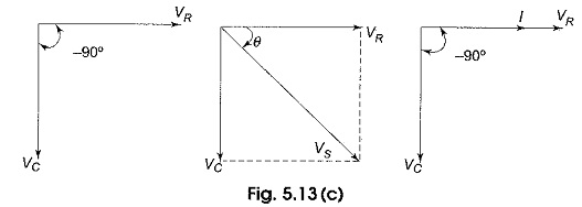
Phasor diagram of rlc circuit. Series RLC Circuit (Circuit & Phasor Diagram) | Electrical4U The phasor diagram of series RLC circuit is drawn by combining the phasor diagram of resistor, inductor and capacitor. Before doing so, one should understand the relationship between voltage and current in case of resistor, capacitor and inductor. Resistor Phasor Diagram and Phasor Algebra used in AC Circuits In their simplest terms, phasor diagrams are a projection of a rotating vector onto a horizontal axis which represents the instantaneous value. As a phasor diagram can be drawn to represent any instant of time and therefore any angle, the reference phasor of an alternating quantity is always drawn along the positive x-axis direction. phasor diagram of parallel lcr circuit - IOT Wiring Diagram Ac Circuit Containing A Resistor An Inductor And Capacitor In Series Rlc Phasor Diagram Formula Solved Example Problems Alternating Cur Use Of Ict In Education For Online And Blended Learning Iit Ay Ppt Parallel Rlc Circuit Analysis Example Problems Electrical A2z PDF Electric Circuits II - Philadelphia University Phasor diagram for series RLC circuit Example: for the circuit shown in figure (a), draw the phasor circuit , impedance diagram and voltages phasor diagram. V=50∟0, so the phasor circuit is shown in figure (b). Z T =Z R +Z L +Z C =3Ω+7Ω-j3Ω =3+j4= 5∟53.13o. Impedance diagram is shown in figure (c). V R =IZ R
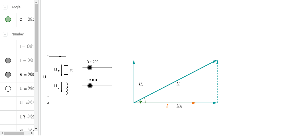
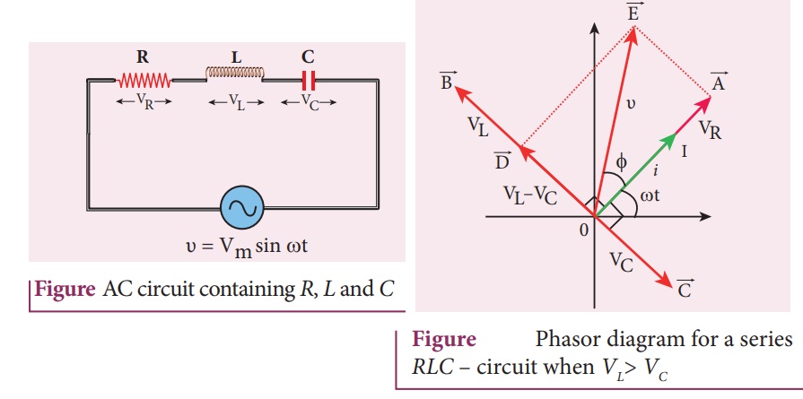
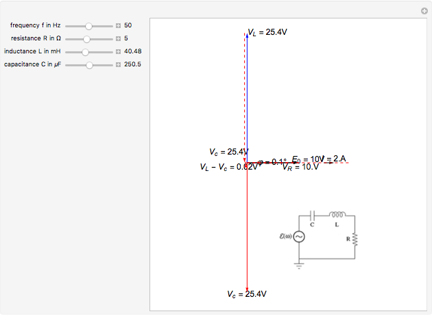
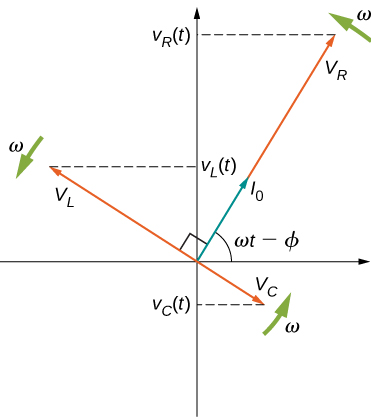
Driven RLC Circuit Using Phasors - GeoGebra Instructions. This simulation shows the phasor representation of a series RLC circuit. Adjust the values of R, L, and C using the sliders. Change how the circuit is driven by adjusting the emf amplitude and driving frequency. Use the check boxes to select which graphs are shown. Phasor Diagram of Parallel RLC Circuit - YouTube Network Theory: Phasor Diagram of Parallel RLC Circuit Topics discussed:1) Phasor diagram of Parallel RLC circuit.2) Current triangle of Parallel RLC circuit... RLC phasor diagram - All About Circuits it is a series RLC circuit. VR(voltage of resistor) is given by 10sin(ωt-53.13°) VL(voltage of inductor) is given by 20sin(ωt+36.87°) VC(voltage of capacitor) is given by 10sin(ωt-143.13°) How about the phasor diagram of E,VR,VL,VC? Phasor Diagram Of Rlc Circuit - U Wiring The phasor diagram for the RLC series circuit shows the main features. The reference vector is labeled E and represents the voltage in the circuit which is common to all elements.
Phasor Diagram For Inductor - U Wiring Draw the phasors for the voltage and the current that correspond to this instant in time. Phasor Diagram of Series RLC Circuit. In circuits which have combinations of L C R in SERIES studied in Module 8 it is customary to draw the phasor representing CURRENT horizontally and call this the REFERENCE phasor. › 35643137(PDF) Network theory by alaxander and sadiku - Academia.edu Academia.edu is a platform for academics to share research papers. Chapter 12.3 - Phasor Diagram of Series RLC Circuit ... The phasor diagram is shown in Figure 12.4 ( c ). Example 12.6. A series RLC circuit consists of a resistance R = 10Ω, inductance L = 0.2H, and capacitance C = 0.2μF. Calculate the frequency of resonance. A10 volts sinusoidal voltage at the frequency of resonance is applied across the circuit. Draw the phasor diagram showing the value of PDF Rlc Circuits Problems And Solutions Friendspetfest RLC Series circuit, phasor diagram with solved problem. An RLC series circuit contains all the three passive electrical components, Resistor Capacitor, and Inductor in series across an AC source. As there is only one path for current in a series combination, the current in all these components is the same in magnitude and phase.
What is RLC Series Circuit? - Phasor Diagram & Impedance ...
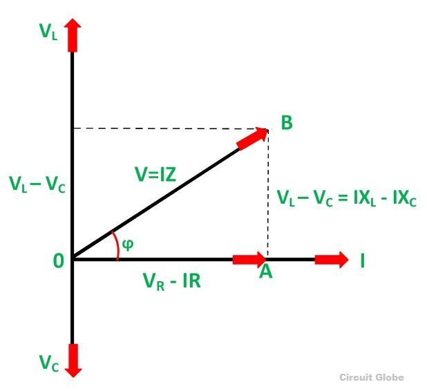
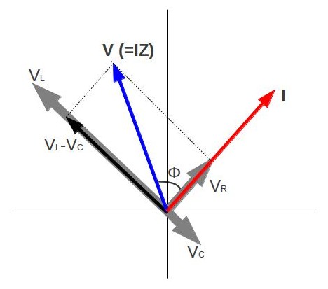
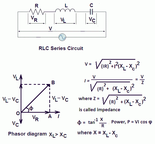
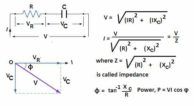
What is RLC Series Circuit? - Phasor Diagram & Impedance PHASOR DIAGRAM OF RLC SERIES CIRCUIT As seen from the phasor diagram that Vₗ and Vc are 180 degree out of phase, they are direct opposite to each other. So effective voltage will be (Vₗ-Vc). Applied voltage is phasor sum of the voltage across resistance & effective voltage. V = √ { (Vr)² + (Vₗ -Vc)²} V = √ { (I*R)² + (I*Xₗ - I*Xc)²}

RLC Circuit -RLC in Series – microdigisoft.com
Solved 3. The Phasor representation of signals in RLC ... The Phasor representation of signals in RLC series circuit You will explore the steady-state response of an RLC circuit to sinusoidal signals at a single frequency and represent these signals in the time and frequency domain. A simple RLC circuit is shown in Figure 1.9: R1 C1 w2413 100 100n R2 wa 3 الا L1 Vs 220u Figure 1.9.

Parallel RLC Circuit Impedance Calculator • Electrical, RF ...
What is RLC Series Circuit? - Phasor Diagram & Impedance ... Steps to draw the Phasor Diagram of the RLC Series Circuit Take current I as the reference as shown in the figure above The voltage across the inductor L that is V L is drawn leads the current I by a 90-degree angle.
Phasor Diagram for Series RLC Circuits - Wolfram ...
Rl Circuit Phasor Diagram - what is rlc series circuit ... Rl Circuit Phasor Diagram. Here are a number of highest rated Rl Circuit Phasor Diagram pictures upon internet. We identified it from obedient source. Its submitted by executive in the best field. We understand this kind of Rl Circuit Phasor Diagram graphic could possibly be the most trending subject afterward we share it in google plus or ...
LCR Series Circuits
RC | RLC | RL Series Circuits - your electrical guide To draw the phasor diagram of RLC series circuit, the current I (RMS value) is taken as the reference vector. The voltages across three components are represented in the phasor diagram by three phasors V R, V L and V C respectively. The voltage drop V L is in phase opposition to V C.

In the figure, which of the phasor diagrams represents `RLC` circuit driven at resonance?
What is phasor diagram of RLC circuit ... A circuit and phasor diagram for a series RLS circuit has been shown below. The phasor diagram of series RLC circuit is drawn by combining the phasor diagram of resistor, inductor and capacitor. Before doing so, one should understand the relationship between voltage and current in case of resistor, capacitor and inductor.
SOLVED:Figure 24-38 shows the phasor diagram for an R L C ...
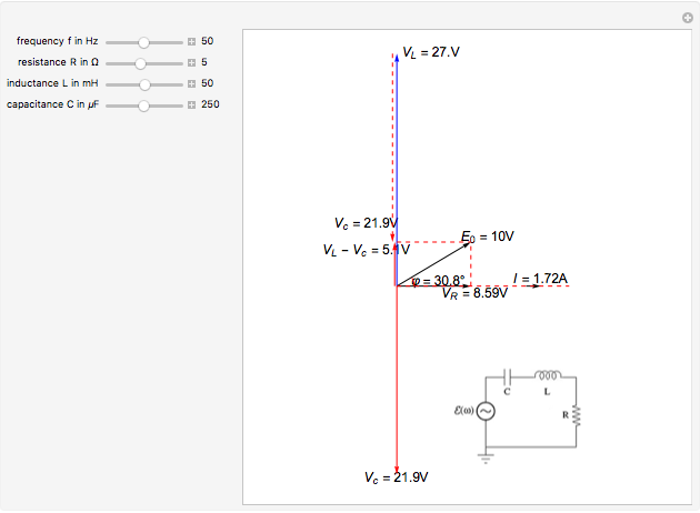
Phasor Diagram for Series RLC Circuits - Wolfram ... This Demonstration shows a phasor diagram in an AC series RLC circuit. The circuit consists of a resistor with resistance , an inductor with inductance , and a capacitor with capacitance . The current in an RLC series circuit is determined by the differential equation [more] where and is the AC emf driving the circuit.
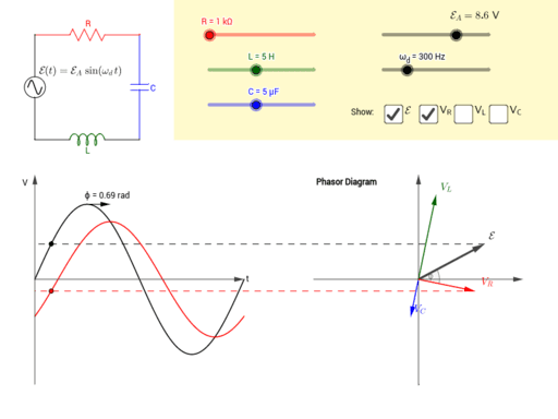
Driven RLC Circuit Using Phasors – GeoGebra
RLC Parallel circuit analysis with solved problem RLC Parallel circuit is the circuit in which all the components are connected in parallel across the alternating current source. In contrast to the RLC series circuit, the voltage drop across each component is common and that's why it is treated as a reference for phasor diagrams.

Series RLC Circuit (Circuit & Phasor Diagram) | Electrical4U
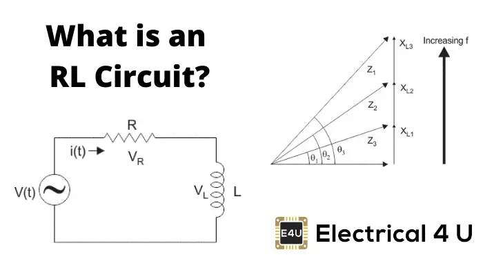
How do you draw a RLC circuit? - handlebar-online.com The phasor diagram of series RLC circuit is drawn by combining the phasor diagram of resistor, inductor and capacitor. How is the sinusoidal response of a series RLC circuit determined? The series RLC circuit above has a single loop with the instantaneous current flowing through the loop being the same for each circuit element.
Series RLC Circuit (Circuit & Phasor Diagram) | Electrical4U
Parallel RL Circuit | Phasor Diagram | Impedance & Power ... Parallel RL Circuit Phasor Diagram. The relationship between the voltage and currents in a parallel RL circuit is illustrated in the vector (phasor) diagram of Figure 2 and summarized as follows: The reference vector is labeled E and represents the voltage in the circuit, which is common to all elements.
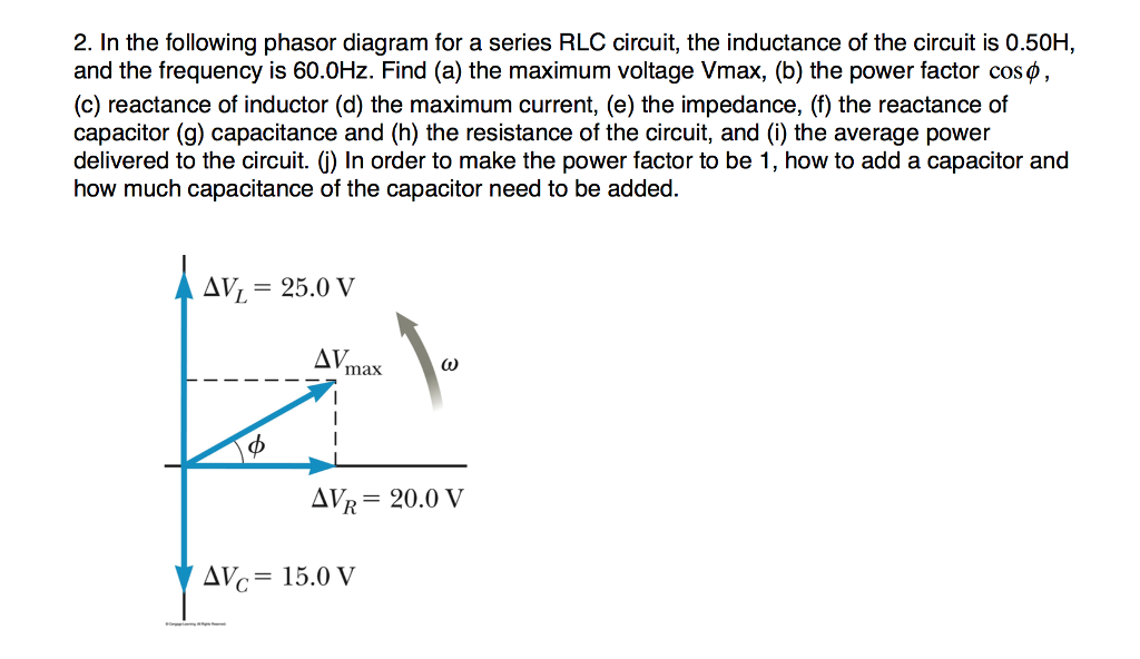
Solved 2. In the following phasor diagram for a series RLC ...
Resonance in series RLC Circuit - Phasor diagram, Circuit ... Phasor diagram, Circuit Diagram, Formula | Alternating Current (AC) - Resonance in series RLC Circuit | 12th Physics : Electromagnetic Induction and Alternating Current Posted On : 24.03.2019 08:39 pm
What is RLC Series Circuit? - Phasor Diagram & Impedance ...
RLC Series circuit, phasor diagram with solved problem For the given circuit diagram calculate the RLC series circuit impedance, current, voltage across each component, and power factor. Also draw the phasor diagram of current and voltage, impedance triangle, and voltage triangle. First of all, let me calculate the total impedance with the following formula Resistance: R=12\Omega
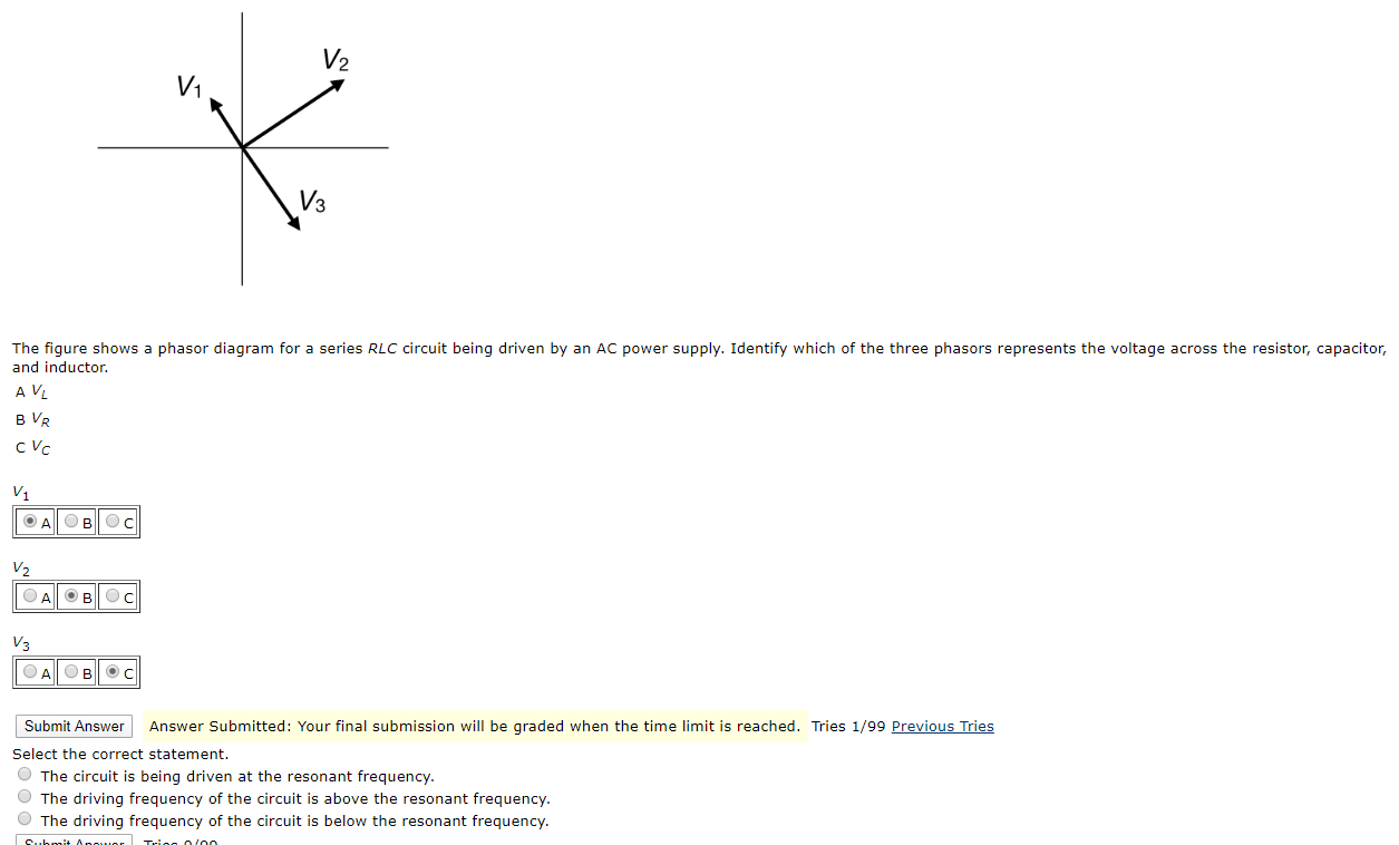
Solved The figure shows a phasor diagram for a series RLC ...
Phasor Diagram of Series RLC Circuit - YouTube Network Theory: Phasor Diagram of Series RLC Circuit Topics discussed:1) Phasor diagram of series RLC circuit.2) Voltage triangle of series RLC circuit.3) Im...
RLC Series Circuits with AC – University Physics Volume 2
Analysis of LCR Circuit, Phasor diagram and FAQs - BYJUS An LCR circuit, also known as a resonant circuit, tuned circuit, or an RLC circuit, is an electrical circuit consisting of an inductor (L), capacitor (C) and resistor (R) connected in series or parallel. The LCR circuit analysis can be understood better in terms of phasors. A phasor is a rotating quantity. Current Vs Voltage Graph.
Phasor Diagram - RL Series Circuit – GeoGebra
What is LC Circuit? Formula, Equitation & Diagram | Linquip Phasor Diagram for a Series RLC Circuit (Reference: electronics-tutorials.ws)
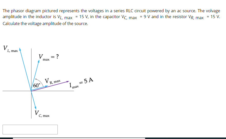
Solved The phasor diagram pictured represents the voltages ...
AC circuit containing a resistor, an inductor and a capacitor ...
Phasor Diagram for Series RLC Circuits - Wolfram ...
Ideal LCR Parallel Circuit

Phasor diagram - LCR circuit - For Xc greater than XL / Capacitive reactance greater than inductive
Series RLC Circuit (Circuit & Phasor Diagram) | Electrical4U
RLC Series Circuits with AC – University Physics Volume 2
Parallel RLC Circuit: Analysis & Example Problems ...

a) Series connection of L C circuit and (b) its phasor ...
AC Circuits | Boundless Physics
RL Series Circuit Analysis (Phasor Diagram, Examples ...

RLC Series circuit, phasor diagram with solved problem

Phasor diagram for LRC circuit
RC | RLC | RL Series Circuits - your electrical guide
Series RLC Circuit (Circuit & Phasor Diagram) | Electrical4U

Parallel RL Circuit | Phasor Diagram | Impedance & Power ...
Series Circuit | Series RL Circuit | Series RC Circuit ...

Solved The phasor diagram below is for an RLC circuit with ...

The phasor diagram for an RLC circuit is shown in the figure ...
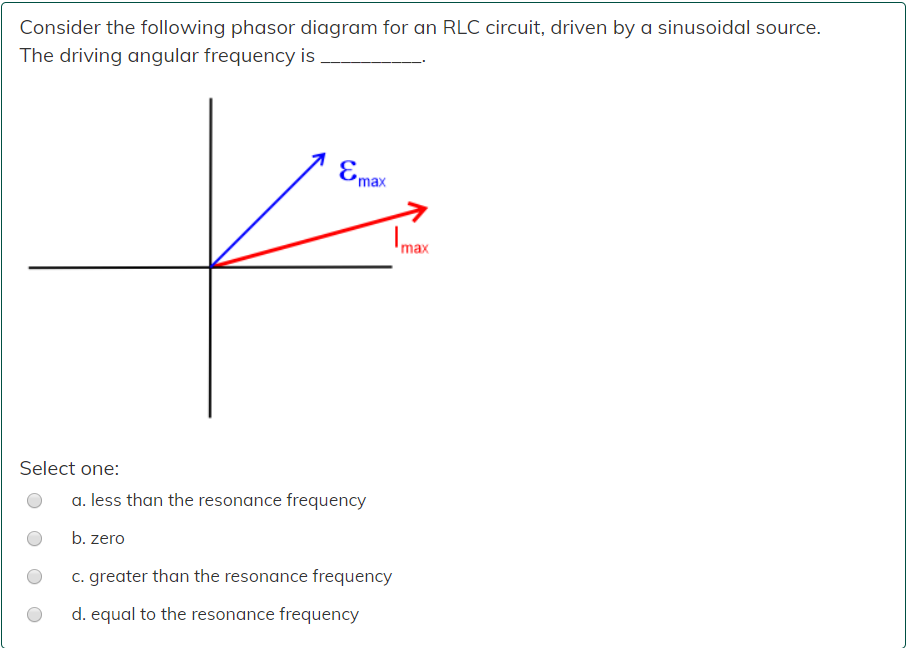
Solved Consider the following phasor diagram for an RLC ...
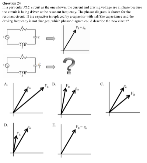
Solved Question 24 In a particular RLC circuit as the one ...
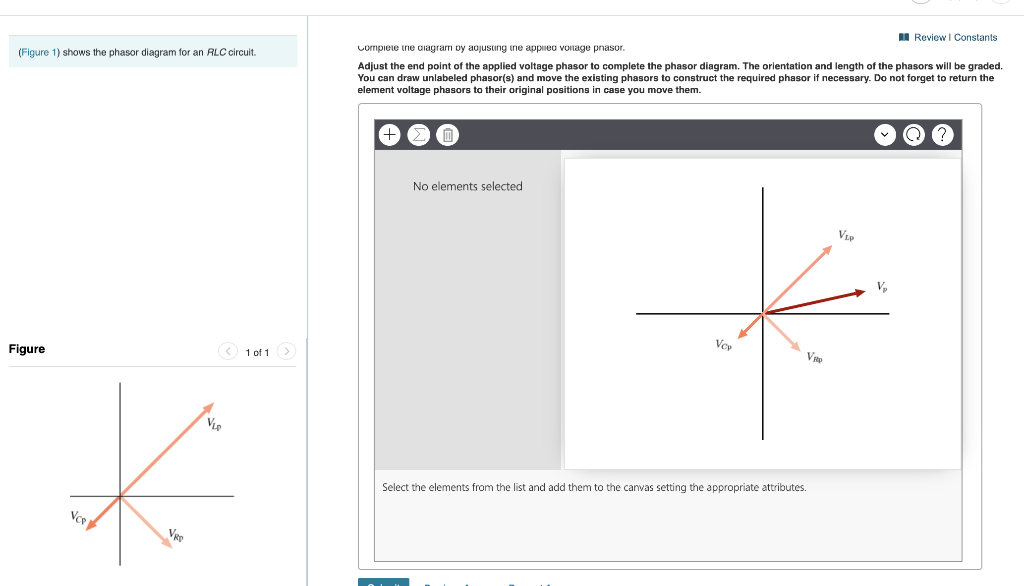
Solved (Figure 1) shows the phasor diagram for an RLC | Chegg.com
RC | RLC | RL Series Circuits - your electrical guide

Phasor diagram of voltage versus current and relationship ...

Series RLC Circuit | Analysis | Phasor Diagram | Impedance ...
Chapter 12.3 - Phasor Diagram of Series RLC Circuit ...
0 Response to "41 Phasor Diagram Of Rlc Circuit"
Post a Comment