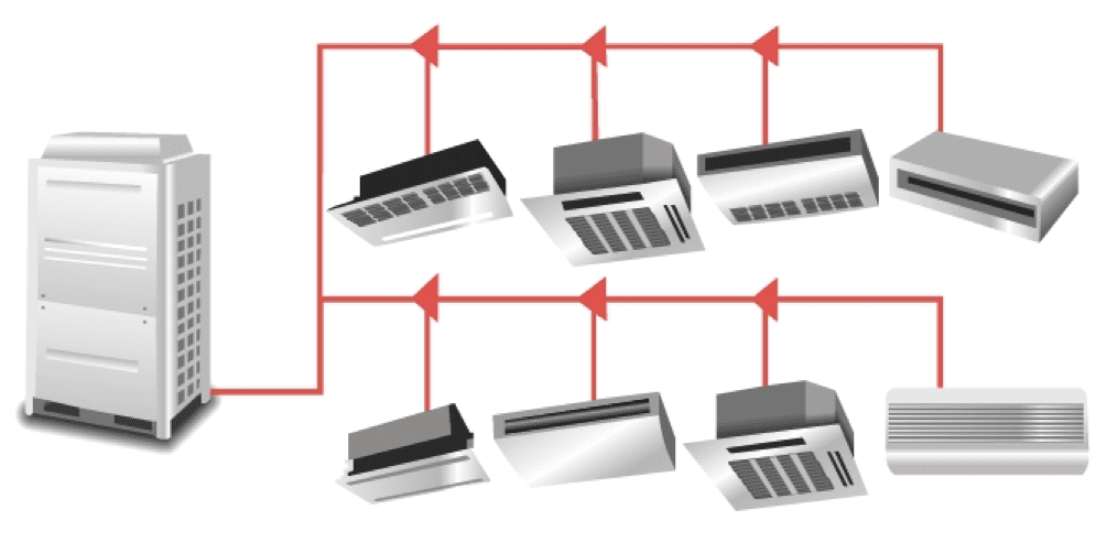
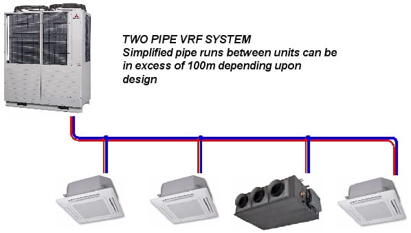
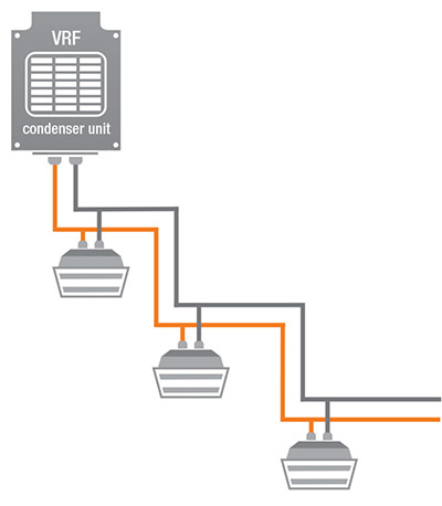
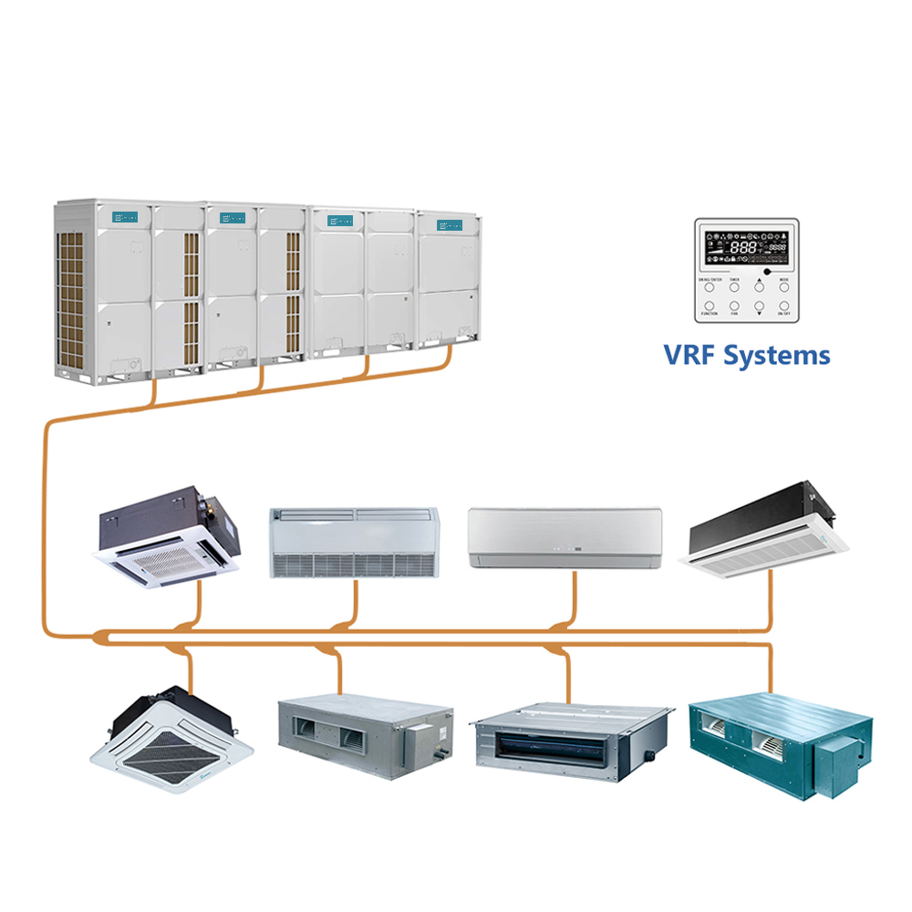
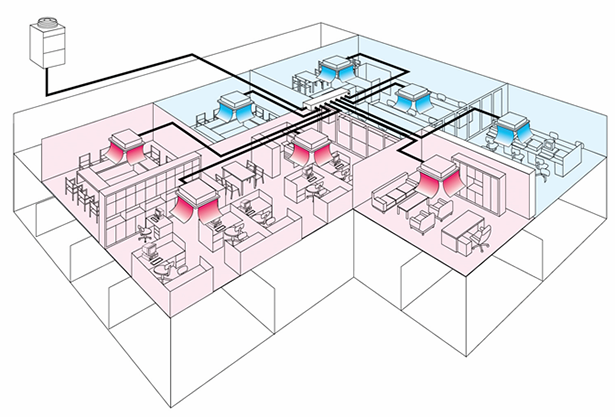
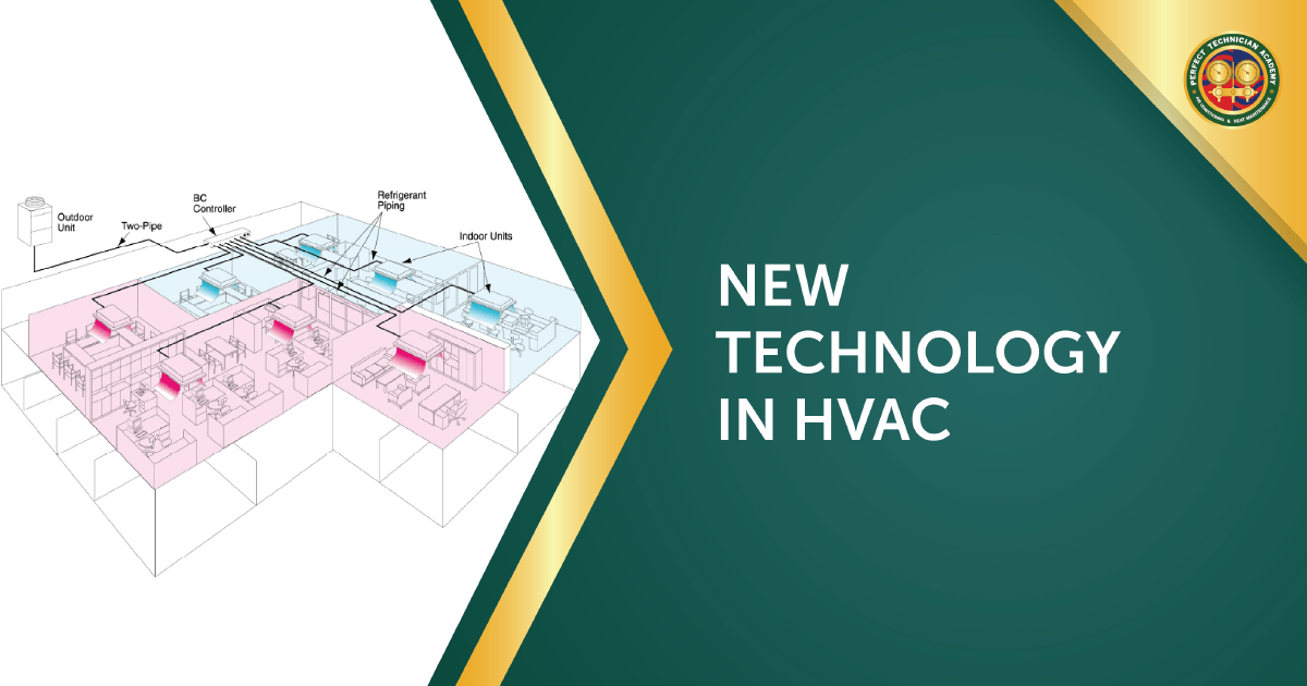
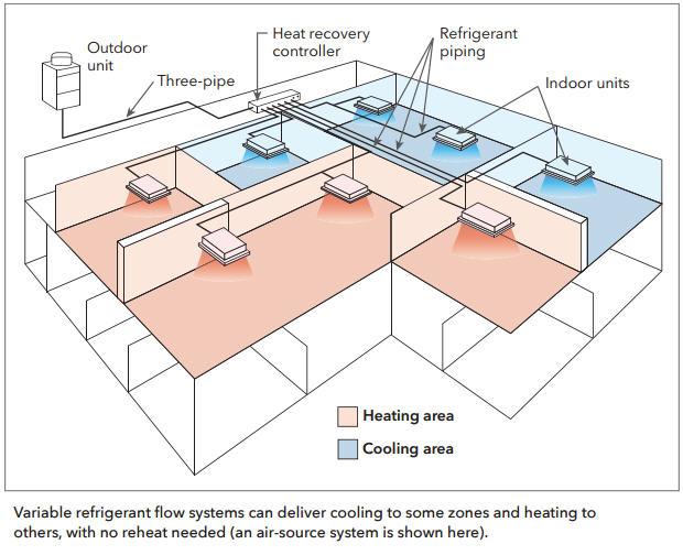
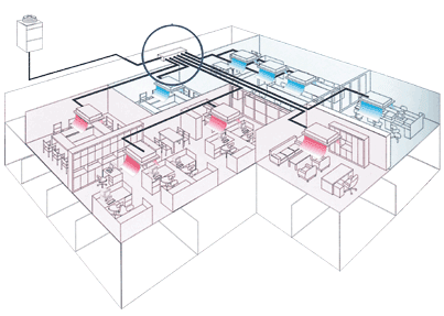
44 vrf air conditioning system diagram
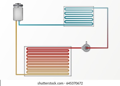
Direct Expansion System - Air Conditioning Systems The diagram above shows a cooling cycle of a heat pump DX system. The valve used is a reversing valve that reverses the refrigerant flow to enable the heat pump to run cooling or heating. A normal valve is used when a cooling only system is needed. This type of system is also known as the vapor compression systems. PDF HVAC Variable Refrigerant Flow Systems Note the term VRF systems should not be confused with the centralized VAV (variable air volume) systems, which work by varying the air flow to the conditioned space based on variation in room loads. Split Air-conditioning Systems Split type air conditioning systems are one-to- one systems consisting of one evaporator
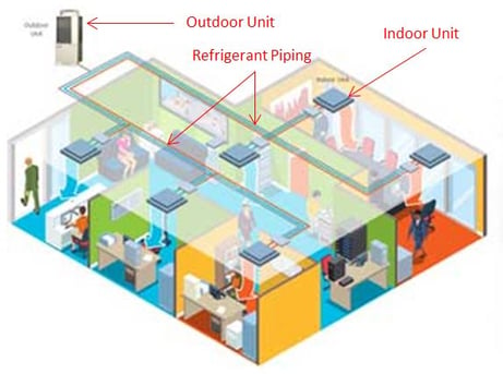
PDF Variable refrigerant flow (VRF) systems - ibse.hk • Variable refrigerant flow (VRF) systems* • Direct expansion (DX), similar to multi-split ... VRF system for centralized air-conditioning in a high-rise commercial building in Manila, Philippines (Source: Dr. Sam C. M. Hui) The plant space design is different from chiller system.
Vrf air conditioning system diagram
PDF VRF Guide Specification A23 3.01 VRF unified heating and cooling (variable refrigerant flow systems) shall have published performance ratings certified by AHRI (Air-Conditioning, Heating, and Refrigeration Institute) and listed in the AHRI Standard 1230 certified product directory. 3.02 All VRF system components shall be manufactured in production facilities maintaining the PDF Designing VRF Systems - ASHRAE Philly VRF systems have been used in Asia and Europe for almost twenty-five years. With a higher efficiency and increased controllability, the VRF system can help achieve a sustainable design. Unfortunately, the design of VRF systems is more complicated and requires additional work compared to designing a conventional DX system. Vrf Electrical Wiring Diagram - Auto Wiring Diagram vrf ac wiring diagram. best daikin air conditioner wiring diagram vrv or vrf electrical s 22mk2e5a s 15mf2e5a s 22mf2e5a s 28mu1e5a s 28mk2e5a s 28my2e5a s 28mf2e5a s 36mt2e5a s 36mu1e5a s 15my2e5a s 36mk2e5a vrf ac wiring diagram. installation operation maintenance manual.
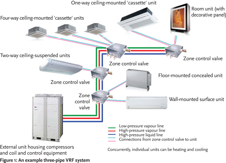
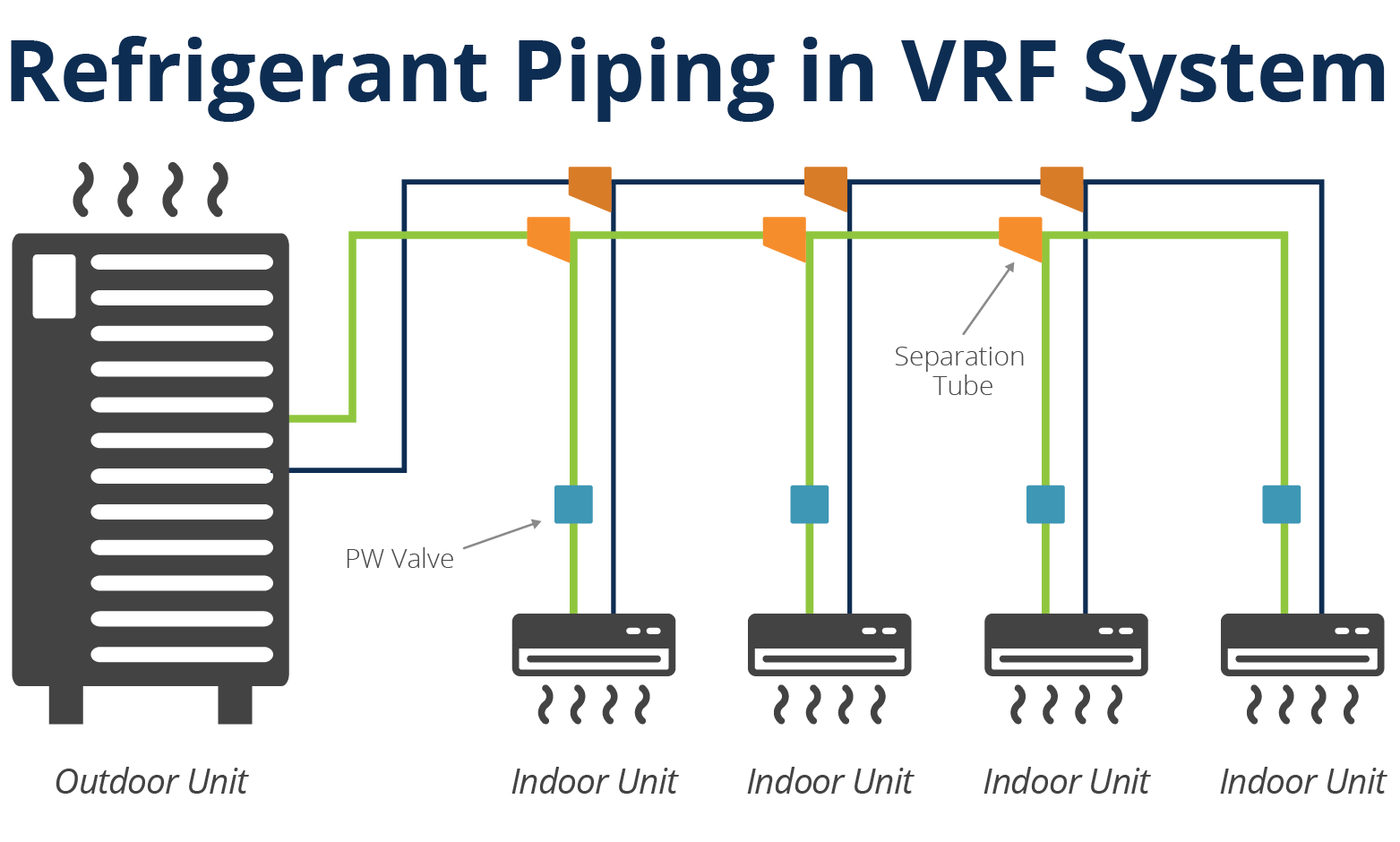
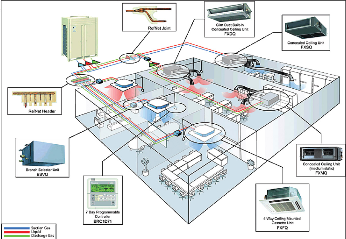
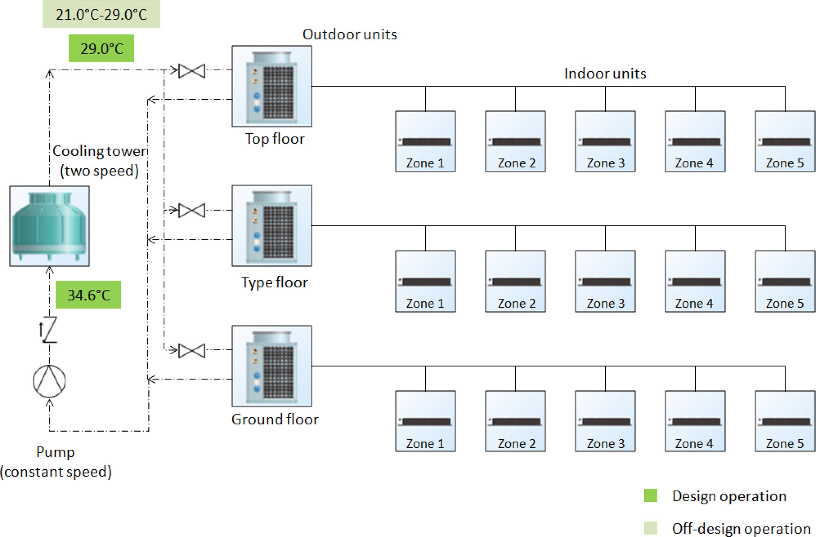
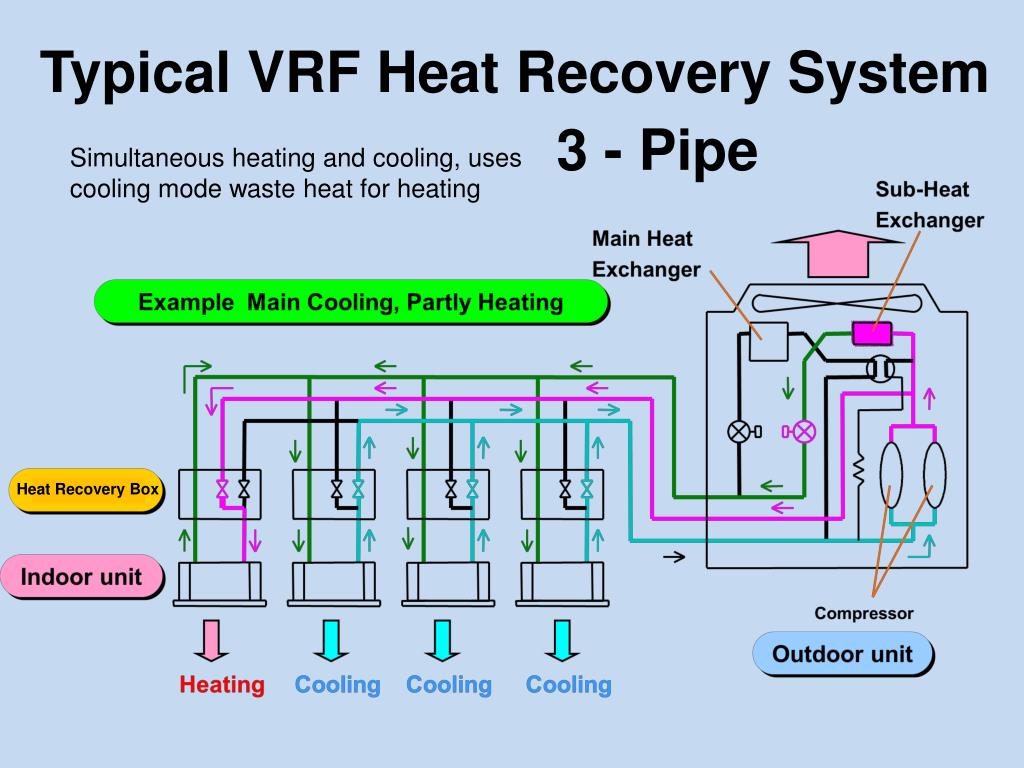
Vrf air conditioning system diagram. VRF System - VRF Air Conditioning System - Blue Star Blue Star provides an extensive range of VRF air conditioners in India, using the latest Variable Refrigerant Flow Technology to manufacture VRF air conditioners. (PDF) Assessing the energy performance of VAV and VRF air ... Figure 4 - Schematic diagram of the VRF system Assessing the energy performance of VAV and VRF air conditioning systems in an office building located in the city of 267 Florianópolis Ambiente Construído, Porto Alegre, v. 20, n. 2, p. 261-283, abr./jun. 2020. What is a VRF System? Variable Refrigerant Flow HVAC ... VRF explained. Complexity is the name of the game when describing the technical nature of how variable refrigerant flow technology works. The simplest explanation of VRF is to describe it as a large-scale ductless HVAC system that can perform at a high capacity. VRF Piping Design Software - Variable Refrigerant Flow Air ... Dec 06, 2017 · Looking at the above VRF piping diagram you can see everything is drawn with a single line, but that there are three dimension (3-Pipe System) for the pipes leaving the Outdoor Unit, and two dimensions (2-Pipes) leaving the branch Selector Box going to the Indoor unit. This makes the drawing is easier to read.
PDF Water Cooled VRF Air Conditioning Systems Water Cooled VRF Air Conditioning System for Apartment Buildings page 2 . VRF SYSTEMS . Variable Refrigerant Flow (VRF) Systems, also called Variable Refrigerant Volume (VRV) Systems, began to emerge in the mid 90's and revolutionised multi-zone air conditioning systems. daikin vrv system wiring diagram pdf - Vrf Sistem Search our exploration, sales, assembly, maintenance, repair and spare parts centers throughout Turkey for your corporate and individual air conditioning needs; let's produce special VRF air conditioning solutions for your space. Vrf Electrical Wiring Diagram ~ Jeusur Interprilo vrf ac wiring diagram. best daikin air conditioner wiring diagram vrv or vrf electrical s 22mk2e5a s 15mf2e5a s 22mf2e5a s 28mu1e5a s 28mk2e5a s 28my2e5a s 28mf2e5a s 36mt2e5a s 36mu1e5a s 15my2e5a s 36mk2e5a vrf ac wiring diagram. installation operation maintenance manual. VRV and VRF Systems - Daikin When Daikin launched the VRV* air conditioning system in 1982, it introduced the world's first use of variable refrigerant volume control. Also referred to as a VRF system, variable refrigerant flow is a technology that circulates only the minimum amount of refrigerant needed during a single heating or cooling period.
Variable air volume - Wikipedia Variable air volume (VAV) is a type of heating, ventilating, and/or air-conditioning system.Unlike constant air volume (CAV) systems, which supply a constant airflow at a variable temperature, VAV systems vary the airflow at a constant temperature. What's the difference between VRV and VRF HVAC ... Think of VRF as the "Rolls-Royce" of Air Conditioning Systems. It's a very sophisticated technological air conditioning system, based on several principles: Refrigerant only - where refrigerant is the only coolant material in the system (in contrary to the chilled water systems, where refrigerant is used for cooling/heating the water ... Samsung VRF Air Conditioning Prices - Vrf System Samsung VRF air conditioning prices are determined on a project-based basis and the capacity of vrf air conditioning is calculated taking into account the needs of your business, the scope of your project, the size of the venue, the number of people in the venue, the climatic conditions of the area where you live, heat sources and losses in the venue, lighting sources and windows in the venue. PDF Installation, Operation, and Maintenance - Trane Variable Refrigerant Flow System Outdoor Unit Series February 2013 VRF-SVN34A-EN Installation, Operation, and Maintenance Models: (HP, 208-230 V) (HP, 460 V) (HR, 208-230 V) (HR, 460V) 4TVH072B300NB 4TVH072B400NB 4TVR072B300NB 4TVR072B400NB 4TVH096B300NB 4TVH096B400NB 4TVR096B300NB 4TVR096B400NB 4TVH120B300NB 4TVH120B400NB 4TVR120B300NB ...
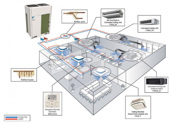
Home VRF System Design Guide with Example and Diagram ... VRF System Diagram Now, let's walk through all the elements involved in the above diagram. VRF Refnet Joint Generally, you need to have about 600mm of straight length clearance before and after a refnet joint to avoid turbulence that can cause improper refrigerant distribution.
VRF | DVM S Variable Refrigerant Flow (VRF) Systems ... Air velocity that is below 0.15 m/s is considered "still air" as defined by ASHRAE 55-2013 (American Society of Heating, Refrigerating, and Air-Conditioning Engineers). Compact size. The small outdoor unit footprints of our VRF systems allow for installation in applications where space is limited, such as on crowded rooftops, or in tight ...
Inverter Air Conditioning Inverter Air Conditioning. The inverter air conditioning is the latest technology in the HVAC field that is becoming more popular due to its environmental friendly and energy savings approach. Providing comfort to the users is another big advantage of this kind of system.
Vrv Air Conditioning Systems Pdf - redledproperty Vrf System Diagram The heat recovery or simultaneous mode systems provide both heating and cooling from the same outdoor unit and thus exploit this technology most effectively.
#VRF System sample Piping diagram.. Arial Engineering ... Aug 23, 2018 - We offer complete solutions for hvac air conditioning system sales, installation and services. vrf, chiller's, ahu, ventilation.HVAC Consultants and Contractors.
carrier vrf piping diagram - Vrf System VRF Air Conditioning Exploration. VRF Air Conditioning Sales. VRF Air Conditioning Installation. VRF Air Conditioning Maintenance. VRF Air Conditioning Service. VRF Air Conditioning Spare Parts. communication. Products tagged "carrier vrf piping diagram". Showing the single result.
PDF HVAC Multi-Split Variable Refrigerant Flow (VRF) Systems The primary function of all air-conditioning systems is to provide thermal comfort for building occupants. There are a wide range of air conditioning systems available, staring from the basic window-fitted unit to the small split systems, medium scale package units, large chilled water systems and very latest variable refrigerant flow (VRF) system.
Components of VRF systems. | Download Scientific Diagram The VRF-OAP system refers to a heating, ventilation, and air conditioning (HVAC) system to complement a ventilation function, which is not provided in the VRF system.
VRF System Control Wiring - Variable Refrigerant Flow Air ... VRF System Control Wiring. This VRF System control wiring is for a VRF VRV Heat Recovery System with single port branch selector boxes. The control wiring is very simple, it's basically two 18 gauge wires that go from the thermostat to the fan coils (Wire #1), so that each zone will have a wire from the thermostat to the fan coil.One controller (Thermostat) can control more than one indoor ...
VRF Systems | Hitachi Heat Pump & Heat Recovery 203/230V, 460V, 575V. View. No Rebates. Change Location. 6-48 Ton Water-Source VRF Systems. 6-48 Ton Water-Source VRF Systems. Solve tough HVAC challenges with water-source heat pump and heat recovery systems. Heat Exchanger Type. Water-source.
Schematic diagram of variable refrigerant flow air ... The variable refrigerant flow (VRF) air conditioning system usually needs to be operated with a ventilation system, since the VRF system cannot provide fresh air.
Vrf Systems Have Changed the Air Conditioning Market | Lg ... Multi-to-multi VRF Flow Diagram Ductless air conditioning systems are fundamentally different from ducted systems in the way they transfer heat. VRF systems circulate refrigerant to indoor units that cool the immediate area where the indoor units are located.
What is a VRF Air Conditioning System? - WGI What is a Variable Refrigerant Flow (VRF) air conditioning system? Here's the definition according to ASHRAE:. The term variable refrigerant flow refers to the ability of the system to control the amount of refrigerant flowing to each of the evaporators, enabling the use of many evaporators of differing capacities and configurations, individualized comfort control, simultaneous heating and ...
Vrf Electrical Wiring Diagram - Ignition Wiring Diagram Vrf Electrical Wiring Diagram Admin 2021-05-24T02:35:00-07:00 5.0 stars based on 35 reviews vrf ac wiring diagram. best daikin air conditioner wiring diagram vrv or vrf electrical s 22mk2e5a s 15mf2e5a s...
Power inverter - Wikipedia The additional electronics and system hardware add cost to the equipment, but can result in substantial savings in operating costs. The first inverter air conditioners were released by Toshiba in 1981, in Japan. Power grid. Grid-tied inverters are designed to feed into the electric power distribution system.
Vrf Electrical Wiring Diagram - Auto Wiring Diagram vrf ac wiring diagram. best daikin air conditioner wiring diagram vrv or vrf electrical s 22mk2e5a s 15mf2e5a s 22mf2e5a s 28mu1e5a s 28mk2e5a s 28my2e5a s 28mf2e5a s 36mt2e5a s 36mu1e5a s 15my2e5a s 36mk2e5a vrf ac wiring diagram. installation operation maintenance manual.
PDF Designing VRF Systems - ASHRAE Philly VRF systems have been used in Asia and Europe for almost twenty-five years. With a higher efficiency and increased controllability, the VRF system can help achieve a sustainable design. Unfortunately, the design of VRF systems is more complicated and requires additional work compared to designing a conventional DX system.
PDF VRF Guide Specification A23 3.01 VRF unified heating and cooling (variable refrigerant flow systems) shall have published performance ratings certified by AHRI (Air-Conditioning, Heating, and Refrigeration Institute) and listed in the AHRI Standard 1230 certified product directory. 3.02 All VRF system components shall be manufactured in production facilities maintaining the










0 Response to "44 vrf air conditioning system diagram"
Post a Comment