45 Phase Locked Loop Block Diagram
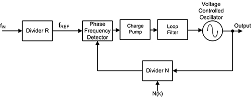
PDF Phase-Locked Loop Basics (PLL) | Charge-Pump PLL Block Diagram Charge-Pump PLL Block Diagram. RefClk Phase-Freq. Detector. [1] B. Razavi, Monolithic Phase-Locked Loops and Clock-Recovery Circuits, IEEE Press, 1996. - collection of IEEE PLL papers. [2] I. Young et al., "A PLL clock generator with 5 to 110 MHz of lock range for... Phase Locked Loop IC | Block Diagram of PLL Phase Locked Loop (PLL) is one of the vital blocks in linear systems. It is useful in communication systems such as radars, satellites, FMs, etc. This chapter discusses about the block diagram of PLL and IC 565 in detail.
PDF Introduction to Phase Locked Loop (PLL) Phase Locked Loop (PLL) is a fundamental part of radio, wireless and telecommunication technology. The goal of this document is to review the theory, design and analysis of PLL circuits. A block diagram of a programmable divider using a dual modulus divider is shown in Figure 9.

Phase locked loop block diagram
Phase locked loop block diagram - YouTube Phase Lock Loop basics, Block Diagram & working in Communication Engineering by Engineering Funda. phase locked loop (PLL) with block diagram explained in Telugu. #phaselockedloop #PLL. How to Layout a Phase-locked Loop IC in Your RF... | Altium Designer Phase-locked loop block diagram. PCB Layout For Your Phase-locked Loop. Phase-locked loop ICs are available on the market that reach Isolation and board gridding: To keep input RF, output RF, and other analog/digital sections from interfering with each other, arrange different circuit blocks into... Writing a Phase-locked Loop in Straight C - liquidsdr.org As its name implies, a phase-locked loop (PLL) is designed to lock the phase of an oscillator to the phase of a reference signal, providing a mechanism for synchronization on different platforms. [analog_pll_diagram] depicts a simplified continuous-time analog PLL.
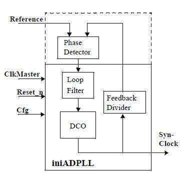
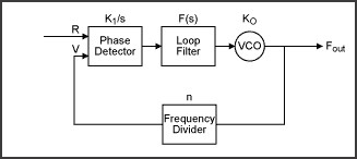
Phase locked loop block diagram. PDF Tutorial on Digital Phase-Locked Loops Why Are Digital Phase-Locked Loops Interesting? Just Enough PLL Background … What is a Phase-Locked Loop (PLL)? ƒ The standard analog PLL implementation is. problematic in many applications. - Analog building blocks on a mostly digital chip pose design and verification challenges. Phase-Locked Loop (PLL) Fundamentals | Analog Devices Phase-locked loop (PLL) circuits exist in a wide variety of high frequency applications, from simple clock clean-up circuits, to local oscillators (LOs) for This article explains some of the building blocks of phase locked loop circuits with references to each of these applications, in turn, to help guide the... PDF Oscillation Control in CMOS Phase-Locked Loops 1 A general PLL block diagram 2 Phase-locked loop 3 Block diagram of the linear PLL 4 Characteristic of an analog mixer 5 XOR phase detector behavior 6 Characteristic of an XOR The most fundamental block diagram of a PLL is shown in Figure 1 [1]. A PLL differs from other feedback... PDF Xilinx XAPP854 Digital Phase-Locked Loop (DPLL) Reference Design... Application Note: Virtex-4 FPGAs. Digital Phase-Locked Loop (DPLL) Reference Design. Figure 1 is a block diagram of the DPLL reference design. In addition to the Virtex-4 FPGA, the design requires two external components: a low-cost digital-to-analog converter (DAC) and a voltage-controlled...
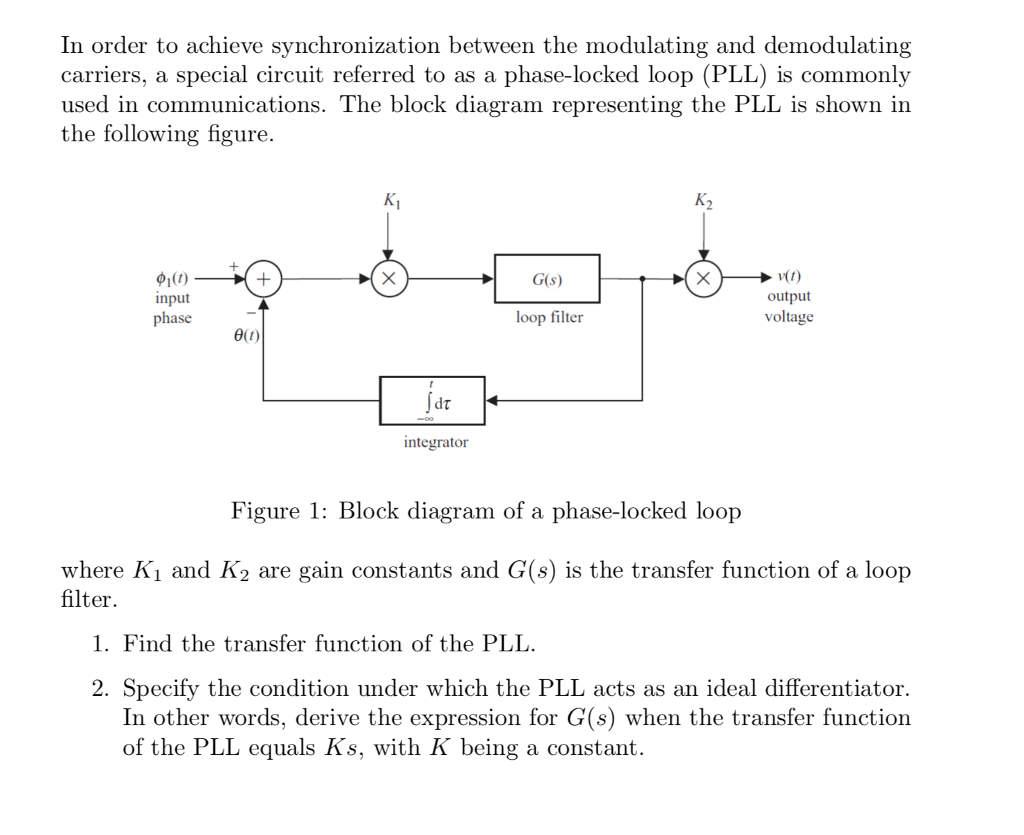
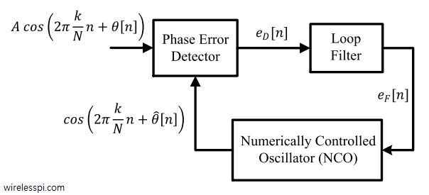
Understanding Phase-Locked Loops Figure 2: Phase-locked loop block diagram. In the weatherfax project, one of the key design issues was to convert a range of audio tones into a video At its most basic, a phase-locked loop (hereafter PLL) compares the frequency of a local reference oscillator to that of a received signal, and uses a... Phase Locked Loop Operating Principle and Applications The below figure shows the block diagram of the PLL. Phase-Locked Loop Detector. The phase-locked loop detector compares the input frequency and the output frequency of the VCO to produces a DC voltage which is directly proportional to the phase distinction of the two frequencies. PDF Phase Locked Loops Design And Analysis Phase-locked loops (PLL) Nonlinear design and analysis. Introduction. Block diagram and mathematical model of PLL. Criterion of global stability of PLL. Costas loop. ICINCO 2008 - 5th International Conference on Informatics in Control, Automation and Robotics... PDF Fpga-based digital phase-locked loop analysis and Phase-locked loop (PLL) is a linear feedback control system that can gener-ate an output signal which has the same frequency and, perhaps, phase as the input Figure 1 (gures are grouped at the end of each chapter) shows the generic block diagram for digital PLL. We denote input signal as x[n] = cos...
Phase-locked loop A phase locked loop or phase lock loop (PLL) is a control system that generates an output signal whose phase is related to the 4.7 Frequency Synthesis. 5 Phase-locked loop block diagram. 6 Elements. Phase-locked loop mechanisms may be implemented as either analog or digital circuits. Phase Locked Loops - an overview | ScienceDirect Topics A phase locked loop (PLL) derived sample clock operates at many times the overall conversion frequency The EPLL proposed in Ref. [38] is made up of the block diagrams of conventional PLL structure with phase detector, loop filter, and VCO sections. Phase-locked loop - Wikipedia A phase-locked loop or phase lock loop (PLL) is a control system that generates an output signal whose phase is related to the phase of an input signal. Phase Locked Loop (PLL) and Delay Locked Loop... - Open4Tech 1 PLL block diagram. The basic operation of PLL can be divided into 3 steps. Delay-Locked Loop (DLL). The DLL is used for phase syncronisation of a reference clock with a system clock. Both the reference clock (CLK_IN) and the system clock (CLK_OUT) have the same frequency.
PDF Phase Locked Loop Block Diagram Phase Locked Loops (PLL) are ubiquitous circuits used in countless communication and engineering applications. A PLL is a truly mixed-signal circuit, involving the co-design of RF, digital, and analog building blocks. A non-linear negative feedback loop that locks the phase of a VCO to a reference...
PDF Phase locked loop | Basic Block Diagram of a PLL Forward path When Phase locked, the loop tracks any change in the input frequency through its repetitive action. If an input signal vs of frequency fs is applied to the PLL, the phase detector compares the phase and frequency of the incoming signal to that of the output vo of the VCO.
Phase-Locked Loop Basics, PLL | Figure 1. PLL Block Diagram A phase-locked loop (PLL) is a closed-loop frequency-control system based on the phase difference between the input clock signal and the feedback clock signal of a controlled oscillator. Figure 1 shows a simplified block diagram of the major components in a PLL.
PLL Phase Locked Loop: How it Works » Electronics Notes The phase locked loop or PLL is a particularly useful circuit block that is widely used in radio frequency or wireless applications. In view of its usefulness, the phase locked loop or PLL is found in many wireless, radio, and general electronic items from mobile phones to broadcast radios...
PDF PFD-CP Phase Locked Loop | Chapter 2. PLL function blocks design phase-locked is called the lock-in range or capture range. For a PLL using PFD and charge pump, the hold range is also only limited by the VCO output frequency range. Every building block of the PLL will contribute to the total output noise. The noise sources of the PLL are shown in the following figure.
Phase Locked Loop Integrated Circuit Phase locked loops (PLLs) can be found in many different types of circuits nowadays. Their applications range from a variety of uses. Figure 25: Simple Ring Oscillator Circuit Block Diagram At every run through the system, each node oscillates between a 1 and 0 due to the inverting action.
PDF Practical Phase-Locked Loop | Charge-Pump PLL Building Blocks Practical Phase-Locked Loop Design. 2004 ISSCC Tutorial Dennis Fischette. • A PLL is a negative feedback system where an oscillator-generated signal is phase and frequency locked to a reference signal. Charge-Pump PLL Block Diagram.
PDF Synthesis of Phase-Locked Loop: analytical methods and simulation Phase-locked loop (PLL) is a circuit invented by a French engineer Anri de Belles-cize in the 1930s (Bellescize, 1932). One of the rst applications of PLL was in the wireless communication (Wendt and Fredentall, 1943; Richman, 1954). In radio-engineering, PLL-based circuits (e.g., a PLL system with a...
Phase Locked Loops, block diagram, working, operation, Design... The block diagram consist of a phase detector which acts as a phase comparator, an amplifier, and a low pass filter with the combination of the resistor The lock range usually increases with an increase in input voltage but falls with an increase in supply voltage. Phase Locked Loop (PLL) - Working.
ww1.microchip.com › downloads › enSAM D21/DA1 Family - Microchip Technology – Internal and external clock options with 48 MHz Digital Frequency-Locked Loop (DFLL48M) and 48 MHz to 96 MHz Fractional Digital Phase-Locked Loop (FDPLL96M) – External Interrupt Controller (EIC) – 16 external interrupts – One Non-maskable Interrupt (NMI) – Two-pin Serial Wire Debug (SWD) programming, test and debugging interface ...
en.wikipedia.org › wiki › Apollo_Guidance_ComputerApollo Guidance Computer - Wikipedia The Block II version is the one that actually flew to the moon. Block I was used during the uncrewed Apollo 4 and 6 flights, and was on board the ill-fated Apollo 1. The decision to expand the memory and instruction set for Block II, but to retain the Block I's restrictive three-bit op. code and 12-bit address had interesting design consequences.
PDF 2.1. Basic operation of a Phase-Locked Loop (PLL) PHASE-LOCKED AND DELAY-LOCKED LOOPS A Dissertation. Presented in Partial Fulfillment of the Requirements for the Degree of Doctor of Philosophy with a Major in Electrical Engineering in the College of Graduate Studies University of Idaho. by Feng Lin.
Block diagram of Phase locked loop(PLL) File:Phase locked loop.svg. From Wikimedia Commons, the free media repository. Jump to navigation Jump to search. There are a wide variety of PLL circuits; this diagram shows the simplest type of analog phase locked loop, which functions as a narrow bandwidth filter.
PDF Phase-Locked Loop Design Fundamentals Phase-Locked Loop Design Fundamentals. by: Garth Nash Applications Engineering. Abstract. The design of a PLL typically involves determining the type of loop required, selecting the proper Laplace Representation of diagram in Figure 11. Phase-Locked Loop Design Fundamentals Application...
Writing a Phase-locked Loop in Straight C - liquidsdr.org As its name implies, a phase-locked loop (PLL) is designed to lock the phase of an oscillator to the phase of a reference signal, providing a mechanism for synchronization on different platforms. [analog_pll_diagram] depicts a simplified continuous-time analog PLL.
How to Layout a Phase-locked Loop IC in Your RF... | Altium Designer Phase-locked loop block diagram. PCB Layout For Your Phase-locked Loop. Phase-locked loop ICs are available on the market that reach Isolation and board gridding: To keep input RF, output RF, and other analog/digital sections from interfering with each other, arrange different circuit blocks into...
Phase locked loop block diagram - YouTube Phase Lock Loop basics, Block Diagram & working in Communication Engineering by Engineering Funda. phase locked loop (PLL) with block diagram explained in Telugu. #phaselockedloop #PLL.





![Activity: The Phase Locked Loop - ADALM2000 [Analog Devices Wiki]](https://wiki.analog.com/_media/university/courses/electronics/a31_f1.png?w=600&tok=cae073)


0 Response to "45 Phase Locked Loop Block Diagram"
Post a Comment