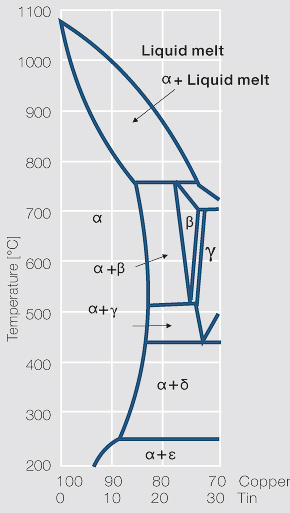
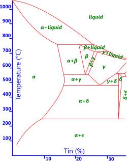
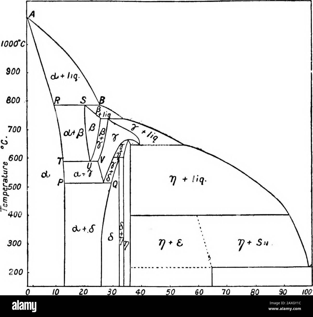
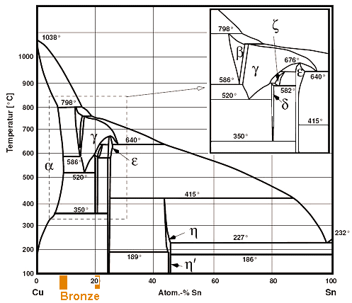
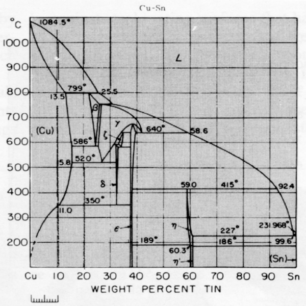
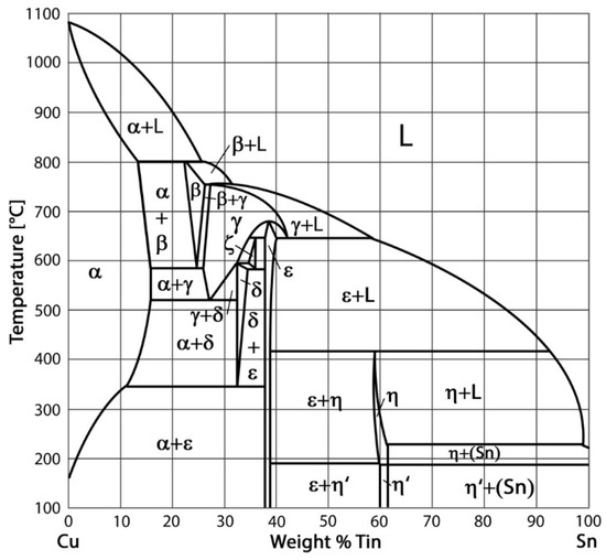
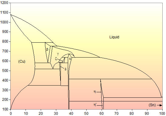
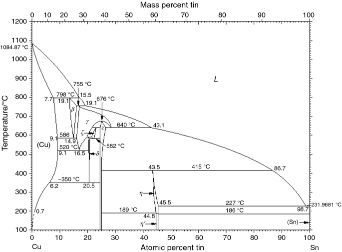
45 copper tin phase diagram
Mechanical Properties of Intermetallic Compounds Formed ... Mechanical Properties of Intermetallic Compounds Formed Between Tin (Solder) and Copper or Nickel. Hardness as a function of temperature for Cu 6 Sn 5, Cu 3 Sn, and Ni 3 Sn 4. Toughness as a function of temperature for Cu 6 Sn 5, Cu 3 Sn, and Ni 3 Sn 4. Elastic moduli, thermal expansion coefficient, resistivity, heat capacity, density, thermal ... PDF Chapter 9 Phase Diagrams - faculty.ksu.edu.sa 1. Locate composition and temperature in diagram . 2. In two phase region draw the tie line or isotherm . 3. Fraction of a phase is determined by taking the length of the tie line to the phase boundary for the other phase, and dividing by the total length of tie line . The lever rule is a mechanical analogy to the mass balance calculation. The ...
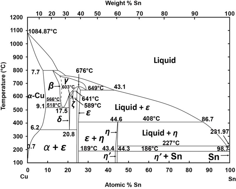
Binary phase diagram of copper-tin under non-equilibrium ... According to the tin content (between 28.7-30.3 wt.%), the intermetallic δ phase of the binary copper-tin system (Fig. 5) is present and has incorporated arsenic, antimony, and silver.

Copper tin phase diagram
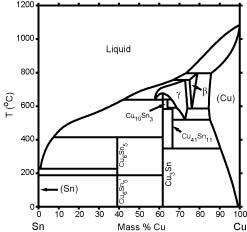
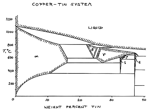
Construction of a Eutectic Phase Diagram The equilibrium phase diagram of the lead-tin system is similar to that of the copper-silver system shown in Figure 4. Due to the low melting point of these alloys, often used as solders, they can be easily melted and cooled in the laboratory. Cu (Copper) Ternary Alloy Phase Diagrams | Alloy Phase ... Abstract. This article is a compilation of ternary alloy phase diagrams for which copper (Cu) is the first-named element in the ternary system. The other elements are Fe, Mn, Ni, Pb, S, Sb, Si, Sn, Ti and Zn. The diagrams are presented with element compositions in weight percent. The article includes 42 phase diagrams (liquidus projection ... 2: Phase diagram for alloys of copper and tin (bronze ... 2: Phase diagram for alloys of copper and tin (bronze). The area above the bold line represent molten alloy. Different mixtures of copper and tin form many kinds of solid phases represented by the ...
Copper tin phase diagram. PDF Chapter 9: Phase Diagrams - Florida International University Phase Diagrams • Indicate phases as function of T, Co, and P. • For this course:-binary systems: just 2 components.-independent variables: T and Co (P = 1 atm is almost always used). • Phase Diagram for Cu-Ni system Adapted from Fig. 9.3(a), Callister 7e. (Fig. 9.3(a) is adapted from Phase Diagrams of Binary Nickel Alloys , P. Nash The Cu–Sn phase diagram, Part I: New experimental ... - NCBI Based on thermal analysis and microscopic methods in 1913 Hoyt published a phase diagram, where those two high temperature phases were separated by a significantly smaller two-phase field. After the invention of X-ray diffraction techniques at the beginning of the 20th century the crystal structure of the Cu-Sn phases could be determined. Cu-Sn Phase Diagram & Computational Thermodynamics Phase Struktur-bericht Symbol Common Names Prototype Spacegroup Model *; Liquid: n/a: L: n/a: n/a (Cu,Sn) 1 Fcc: A1 (Cu) Cu: Fm-3m (Cu,Sn) 1 (Va) 1Bcc: A2 (beta Cu), beta: W: Im-3m (Cu,Sn) 1 (Va) 3Bct: A5 (Sn), (beta Sn) The copper-tin phase diagram, compare [6] | Download ... Download scientific diagram | The copper-tin phase diagram, compare [6] from publication: High Temperature Shear Strength of Cu-Sn Transient Liquid Phase Sintered Interconnects | In this paper, we ...
Phase Diagram - SlideShare Phase Diagram 1. Chapter-5 PHASE AND PHASE EQUILIBRIUM Prepared By: PALLAV RADIA Asst prof. AITS, RAJKOT. 2. Introduction: One of the most important objective of engineering metallurgy is to determine properties of material. The properties of material is a function of the microstructure which depend on the overall composition and variable such as pressure and temperature. Hence to determine ... The Cu-Sn (Copper-Tin) system | SpringerLink C. Haase and F. Pawlek, “Copper-Tin Alloys,” Z. Metallkd., 28, 73–86 (1936). (Equi Diagram, Crys Structure; Experimental) Google Scholar. S.T. Konobeevskii and W.P. Tarrassova, “The Equilibrium Diagram for the System Cu-Sn and the Transformation Associated with the Decomposition of the Solid Solution a ,” Acta Physiochim. Some Phase Diagrams Some Phase Diagrams: Here are two phase diagrams for illustration purposes. I've chosen the diagrams for two old acquaintances: The system copper (Cu) - tin (Sn) The system copper (Cu) - zinc (Zn) Let's start with copper (Cu) - tin (Sn). This system contains what we call "bronze". Here is the phase diagram: Sn (Tin) Binary Alloy Phase Diagrams | Alloy Phase ... Abstract. This article is a compilation of binary alloy phase diagrams for which tin (Sn) is the first named element in the binary pair. The diagrams are presented with element compositions in weight percent. The atomic percent compositions are given in a secondary scale. For each binary system, a table of crystallographic data is provided that ...
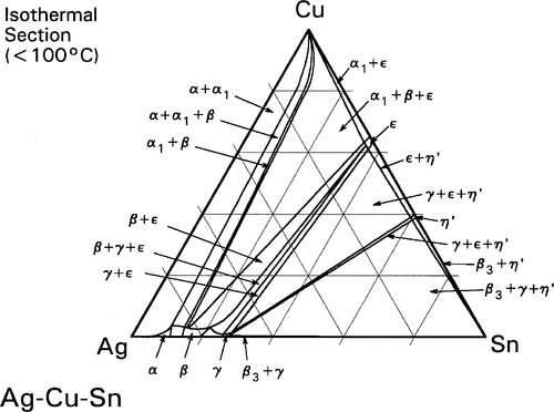
PDF Silver - Copper - Tin well [81Fed], thus supporting the proposed ternary equilibrium diagram given by [59Geb]. Ag-Cu-Sn alloys form the basis of dental amalgams. A knowledge of the phase relationships Copper & Copper Alloy Microstructures: Copper Tin Alloys Tin bronzes, with up 15.8% tin, retain the structure of alpha copper. The tin is a solid solution strengthener in copper, even though tin has a low solubility in copper at room temperature. The room temperature phase transformations are slow and usually do not occur, therefore these alloys are single phase alloys. The Cu–Sn phase diagram, Part I: New experimental results Phase diagram investigation of the Cu-Sn system was carried out on twenty Cu-rich samples by thermal analysis (DTA), metallographic methods (EPMA/SEM-EDX) and crystallographic analysis (powder XRD, high temperature powder XRD). One main issue in this work was to investigate the high temperature phases beta (W-type) and gamma (BiF 3 -type) and ... Solved PROBLEMS 6.1. For the copper-nickel phase diagram ... Using the lead-tin phase diagram; Question: PROBLEMS 6.1. For the copper-nickel phase diagram in Figure 6.2, find the compositions of the liquid and solid phases for a nominal composition of 70% Ni and 30% Cu at 1371°C (2500°F). 6.2.
Standards & Properties: Metallurgy of Copper-Base Alloys All of the three qualities above are directly related to the structure and behavior of copper's structure on an atomic scale. Solid copper can be described as the arrangement of copper atoms in a face-centered-cubic (fcc) configuration. A copper atom is found at each corner and in the center of each face of a cube as depicted in Figure 1. This is the unit cell which is repeated in three dimensional space to make up the crystal structure of the metal. The atoms are held in place in the structure by the energy of the atomic attractions between them. It is this particular face-centered cubic arrangement of the atoms that gives copper its high ductility and toughness. All metals deform by means of a mechanism called slip. When slip occurs, a force on the metal causes the atoms to slide past one another in groups. In the copper fcc structure this movement occurs preferentially in any or all of three directions along a specific geometric plane of atoms within the lattice, as shown in Figu...
Modern uses - DoITPoMS Modern uses. Phase diagrams are not just an abstract construction - they have applications in the real world, in deciding which compositions to use. A major use of eutectics, or near eutectics is in solder. In plumbing, solder is used to join copper pipes together, producing a waterproof seal. For many years a lead-tin alloy has been used, as ...
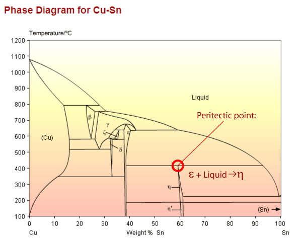
Copper based alloys - DoITPoMS Copper tin phase diagram showing a peritectic point The peritectic reaction (see diagram above) is an important example of a microstructural transformation. Sn - 21wt.%Cu exhibits this transformation from a solid phase and a liquid phase to a different, solid phase. Re-use of this resource is governed by a Creative Commons Attribution-
The Cu-Sn phase diagram, Part I - CiteSeerX by S Fürtauer · 2013 · Cited by 208 — The binary system CueSn is the key system for lead-free soldering, because tin is the main component of most of such solder materials and Cu is ...
PDF Phase Diagram Bi-Sn - Santa Rosa Junior College Copper) Small Rise when going from one to other, even though one has much lower value. ... low enough temp. that the phase diagram shows nothing more is going on. ... Sample # Bismuth Tin Sample # Bismuth Tin 1 100 0 1 10 0 2 97.5 2.5 2 9.74 0.25093 3 95 5 3 9.5153 0.4999
PPT PowerPoint Presentation % Type Pure copper Cu-15Ni-8Sn Cu3Sn solder solder Cu6Sn5 (Cu,Ni)6Sn5 Cu-1.9Be-0.4Co Cu-9Ni-6Sn solder solder (Cu,Ni)6Sn5 Cu3Sn Cu6Sn5 (CuNi)6Sn5 Cu-15Ni-8Sn Pb-rich 60Sn-40Pb Ni3Sn2 has hexagonal B82 structure with structural vacancies at nickel sites Cu55Sn45 analogous hexagonal B81 structure with copper atoms at these same sites Both phases ...
PDF Chapter Outline: Phase Diagrams MSE 2090: Introduction to Materials Science Chapter 9, Phase Diagrams 24 Binary Eutectic Systems (III) Lead - Tin phase diagram Invariant or eutectic point Eutectic isotherm Temperature, ° C Composition, wt% Sn Eutectic or invariant point- Liquid and two solid phases co-exist in equilibrium at the eutectic composition CE and the eutectic ...
PDF Lecture 19: 11.23.05 Binary phase diagrams Eutectic phase diagram for a silver-copper system. 2800 2600 2400 2200 2000 1800 1600 MgO CaO 20 40 60 80 100 0 C) L MgO ss + L MgO ss CaO ss + L CaO ss MgO ss + CaO ss Wt % Eutetic phase diagram for MgO-CaO system. Temperature (Lecture 19 - Binary phase diagrams 4 of 16 11/23/05
Tin Alloys - an overview | ScienceDirect Topics Figure 2.10 shows the phase diagram for the lead-tin system. ... Bronze age (3,000 BC-1,000 BC). It is used in many forms: as pure copper, as copper-zinc alloys (brasses), as copper-tin alloys (bronzes), and as copper-nickel and copper-beryllium. The designation of "copper" is used when the percentage of copper is more than 99.3%.
The Cu-Pb-Sn (copper-lead-tin) system | SpringerLink B. Blumenthal, "The Constitution of the Copper-Tin-Lead System ... N. Saunders and A.P. Miodownik, "The Cu-Sn (Copper-Tin) System,"Bull. Alloy Phase Diagrams, 11(3), 278-287 (1990). (Review; #) Article Google Scholar Download references. Author information. Affiliations. National Metallurgical Laboratory, 831 007, Jamshedpur, India ...
PDF Phase Diagrams for Lead-Free Solder Alloys has been pre-tinned with a tin-lead or tin-bismuth alloy with a solder of a different composition may result in the formation of a low-melting higher-component eutectic. In this case, the multi-component phase diagram can be used to evaluate the possible effects resulting from such a contamination. Traditionally, phase diagrams are
PDF Teach Yourself Phase Diagrams and Phase Transformations Teach Yourself Phase Diagrams A.6 HRS 03/11/2009 and Phase Transformations DEF.The equilibrium constitution is the state of lowest Gibbs free energy G, for a given composition, temperature and pressure. An alloy in this state shows no tendency to change - it is thermodynamically
PDF Chapter 9 Phase Diagrams Problem Solutions 9.34 Consider the hypothetical eutectic phase diagram for metals A and B, which is similar to that for the lead-tin system, Figure 9.8. Assume that (1) α and β phases exist at the A and B extremities of the phase diagram, respectively; (2) the eutectic composition is 47 wt% B-53 wt% A; and (3) the composition of the β phase at
2: Phase diagram for alloys of copper and tin (bronze ... 2: Phase diagram for alloys of copper and tin (bronze). The area above the bold line represent molten alloy. Different mixtures of copper and tin form many kinds of solid phases represented by the ...
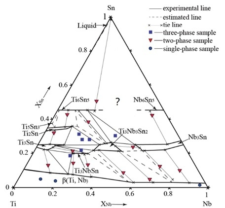
Cu (Copper) Ternary Alloy Phase Diagrams | Alloy Phase ... Abstract. This article is a compilation of ternary alloy phase diagrams for which copper (Cu) is the first-named element in the ternary system. The other elements are Fe, Mn, Ni, Pb, S, Sb, Si, Sn, Ti and Zn. The diagrams are presented with element compositions in weight percent. The article includes 42 phase diagrams (liquidus projection ...
Construction of a Eutectic Phase Diagram The equilibrium phase diagram of the lead-tin system is similar to that of the copper-silver system shown in Figure 4. Due to the low melting point of these alloys, often used as solders, they can be easily melted and cooled in the laboratory.
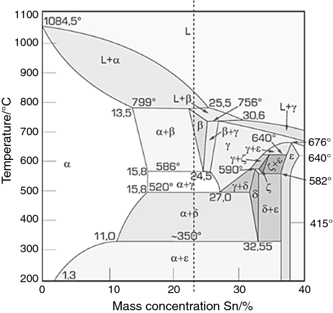
![The copper-tin phase diagram, compare [6] | Download ...](https://www.researchgate.net/profile/Seyed-Ali-Moeini/publication/290194359/figure/fig1/AS:318204485357568@1452877269548/The-copper-tin-phase-diagram-compare-6.png)
![PDF] Microanalysis of Copper-Tin Phases in Dental Amalgam ...](https://d3i71xaburhd42.cloudfront.net/633e50ee2c2d0a31ad08f279e7c28b8c96239fe3/2-Figure1-1.png)









![The copper-tin phase diagram, compare [6] | Download ...](https://www.researchgate.net/profile/Seyed-Ali-Moeini/publication/290194359/figure/fig1/AS:318204485357568@1452877269548/The-copper-tin-phase-diagram-compare-6_Q320.jpg)

0 Response to "45 copper tin phase diagram"
Post a Comment