42 d flip flop state diagram
PDF Edge-triggered Flip-Flop, State Table, State Diagram • 2. Formulation: Draw a state diagram • 3. Assign state number for each state • 4. Draw state table • 5. Derive input equations • 5. One D flip-flop for each state bit . Example • Design a sequential circuit to recognize the input sequence 1101. • That is, output 1 if the sequence 1101 has been read, output 0 ... Converting State Diagrams to Logic Circuits Examining State 3 on our state diagram reveals that this will move us into State 4, the output of which has the bulb off. Flip-flop Review. Let's refresh our memory on flip-flops. In general, the flip-flops we will be using match the diagram below. It has three inputs (D, CLK, and ^R) and one output (Q).
D Flip-Flop [classic] | Creately D Flip-Flop [classic] by Emmanuel Marques Scur. Edit this Template. Use Creately's easy online diagram editor to edit this diagram, collaborate with others and export results to multiple image formats. D Flip-Flop with reset. logic gates logicgates network tech. Flowchart Templates. Org Chart Templates.

D flip flop state diagram
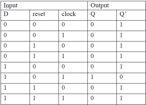
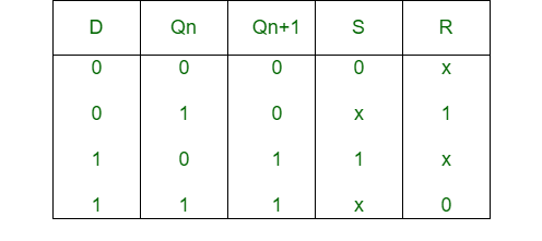
Verilog code for D flip-flop - All modeling styles It applies to flip flops too. Hence, we will include a clear pin that forces the flip flop to a state where Q = 0 and Q' = 1 despite whatever input we provide at the D input. This clear input becomes handy when we tie up multiple flip flops to build counters, shift registers, etc. Behavioral Modeling of D flip flop with Synchronous Clear For the state diagram below, if a T flip flop and a D ... Transcribed image text: For the state diagram below, if a T flip flop and a D flip flop are used, then what is the equation for the input of T and D flip flop? (Assume T and D is the input of T flip flop and D flip flop respectively, Qt and Qd are the outputs of T flip flop and D flip flop respectively, and A, B are the external inputs). 00 XX 1 01 10 01,1X Dxx 00 1 0 XX 11 01,1X D 00 1 Please ... What is state diagram of d flip flop? - Answers state diagram of d flip flop is same as applied input it means. >if you are going to 0 to 0 than Qn =0 >if you are going to 0 to 1 than Qn= 1 >if you are going to 1 to 0 than Qn = 0 >if you are ...
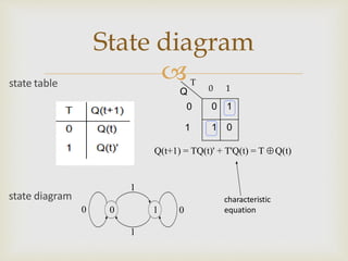
D flip flop state diagram. D Flip Flop in Digital Electronics - Javatpoint Thus, the level-sensitive D-type or D flip flop is constructed from a level-sensitive SR flip flop. So, here S=D and R= ~D (complement of D) Block Diagram Circuit Diagram We know that the SR flip-flop requires two inputs, i.e., one to "SET" the output and another to "RESET" the output. What is D Flip Flop? The D flip-flop is a clocked flip-flop with a single digital input 'D'. Each time a D flip-flop is clocked, its output follows the state of 'D'. The D Flip Flop has only two inputs D and CP. The D inputs go precisely to the S input and its complement is used to the R input. Considering the pulse input is at 0, the outputs of gates 3 and ... State Diagram Of T Flip Flop - U Wiring Mealy state diagram of a JK flip-flop CLK a b Q Q J K 100 110 011 111 001 101 000 010 Inputs. USING JK AND T FLIP-FLOPS Analysis with Other Flip-Flop Types So far we have considered the state table for sequential circuits that employ D-type flip-flops in which case the next-state values are obtained directly from the input equations. Designing of D Flip Flop - Electronics Hub A D flip - flop is constructed by modifying an SR flip - flop. The S input is given with D input and the R input is given with inverted D input. Hence a D flip - flop is similar to SR flip - flop in which the two inputs are complement to each other, so there will be no chance of any intermediate state occurs.
Flip-Flops its Basic Types along with Block Diagrams D flip-flop (delay) J-K flip-flop; T flip-flop (1) SET-RESET Flip-Flop. This flip-flop possesses a property of holding a state until any further signal applied. There are two inputs to the flip-flop set and reset. When the set signal is applied it sets the value of flip-flop output to 1, the outputs are switched to 0 when the reset signal is ... state diagram/state table/circuit diagram (using D-flip ... a method to solve combination of 3 or more 1(s) using state tables and the consequently applying principle of D flip flophope this video was helpful D Type Flip-flops - Learn About Electronics The basic D Type flip-flop shown in Fig. 5.3.1 is called a level triggered D Type flip-flop because whether the D input is active or not depends on the logic level of the clock input. Provided that the CK input is high (at logic 1), then whichever logic state is at D will appear at output Q and (unlike the SR flip-flops) Q is always the inverse ... State Diagram Of Sequential Circuit Using D Flip Flop ... On this channel you can get education and knowledge for general issues and topics
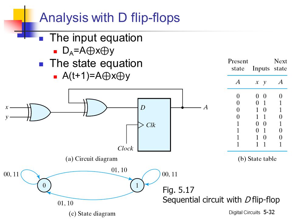
CSCE 436 - Lecture Notes - Computer Science and Engineering The D flip flop Since D flip flops will be a major part of this lecture, it's worth spending a few minutes reviewing their operation. To start out, complete the following timing diagram for the output of the negative-edge triggered D flip-flop with an asynchronous active low reset line. PDF Circuits with Flip-Flop = Sequential Circuit Circuit ... Circuit, State Diagram, State Table Circuits with Flip-Flop = Sequential Circuit Circuit = State Diagram = State Table State Minimization Sequential Circuit Design Example: Sequence Detector Example: Binary Counter Flip flop's state tables & diagrams - SlideShare Jun 18, 2013 · SR Flip-flop State table & Diagram D Flip-flop State table & Diagram JK Flip-flop State table & Diagram T Flip-flop State table & Diagram 3. a flip-flop is a type of circuit that contains two states and are often used to store state information. By sending a signal to the flip-flop, the state can be changed. Flip-flops are used in a number of ... D Flip Flop Based Implementation Digital Logic Design ... Flip-Flop Transition Table To implement the counter using D flip-flops instead of J-K flip-flops, the D transition table is used. The D flip-flop only has a single input and the output of the D flip-flop follows the input. The D flip-flop transition table is shown. Table 32.1 Flip-flop Output Inputs Transitions D Q t+1 1 1 0 0 Table 32.1
State Tables and State Diagrams
PDF Latches, the D Flip-Flop & Counter Design - UC Santa Barbara Counter Design with D Flip-Flops State diagram 00 01 10 0 0 0 1 1 1. February 6, 2012 ECE 152A - Digital Design Principles 49 Counter Design with D Flip-Flops

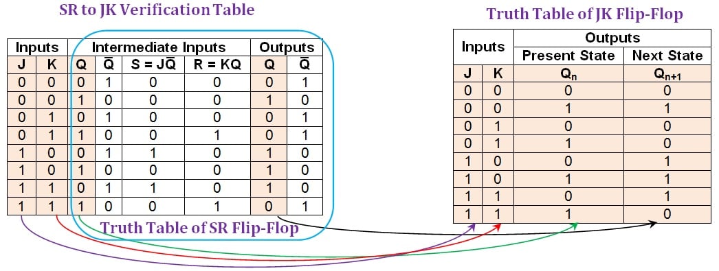
JK Flip Flop and SR Flip Flop - GeeksforGeeks
D Type Flip Flop: Circuit Diagram, Conversion, Truth Table The circuit diagram of the edge triggered D type flip flop explained here. First, the D flip-flop is connected to an edge detector circuit, which will detect the negative edge or positive edge of the clock pulse. Then, according to the output of the edge detector circuit, the D flip flop will operate accordingly.
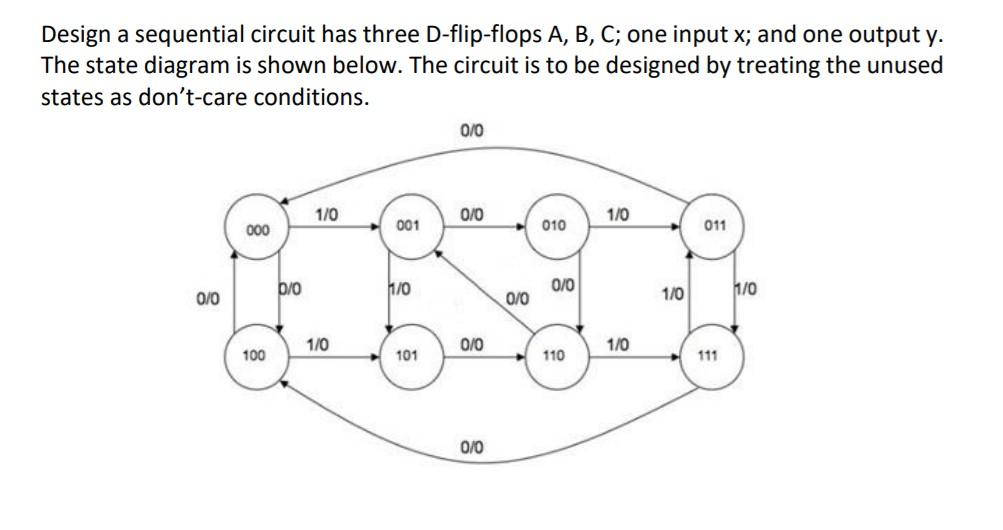
Solved Design a sequential circuit has three D-flip-flops A ...
D Flip Flop (D Latch): What is it? (Truth Table & Timing ... A D Flip Flop (also known as a D Latch or a 'data' or 'delay' flip-flop) is a type of flip flop that tracks the input, making transitions with match those of the input D. The D stands for 'data'; this flip-flop stores the value that is on the data line. It can be thought of as a basic memory cell. In an active high SR Flip Flop is ...
11.5 Finite State Machines
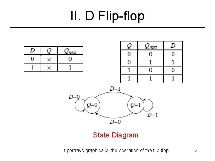
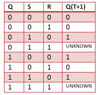
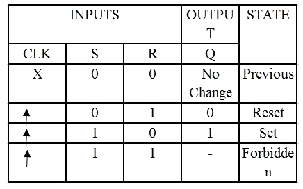
What is D flip-flop? Circuit, truth table and operation. Operation and truth table of D flip-flop If D = 1, then the inputs for the SR flip flop are S = 1, R =0. When you look at the truth table of SR flip flop, the next state output is logic 1, which will SET the flip flop. When D = 0, the inputs of SR flip flop will become, S = 0, R = 1.
STATE DIAGRAM AND STATE TABLES - ppt video online download
Flip Flops in Electronics-T Flip Flop,SR Flip Flop,JK Flip ... 2. D Flip Flop. The circuit diagram and truth table is given below. D Flip Flop. D flip flop is actually a slight modification of the above explained clocked SR flip-flop. From the figure you can see that the D input is connected to the S input and the complement of the D input is connected to the R input.

Introduction to D flip flop
Digital Circuits - Flip-Flops - Tutorialspoint The circuit diagram of D flip-flop is shown in the following figure. This circuit has single input D and two outputs Q t & Q t '. The operation of D flip-flop is similar to D Latch. But, this flip-flop affects the outputs only when positive transition of the clock signal is applied instead of active enable.
JK-flipflop-State-Machine | Metastability Finite State ...
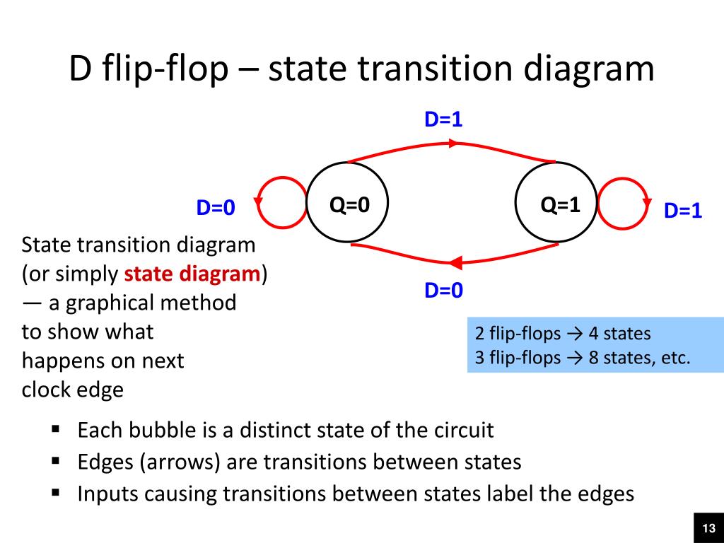
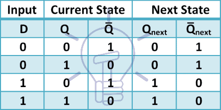
D Flip Flop: Circuit, Truth Table, Working, Differences ... Fig. State diagram of the D flip-flop When the state changes from 0 to 1, it is caused by the input D, which is high, and when the output state is 0, and at the time D=0 that produces no change in the output, the arrow with D=0 starts with state 0 and also returns to state 0. ASM Chart for D flip flop
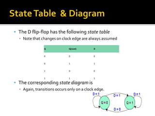
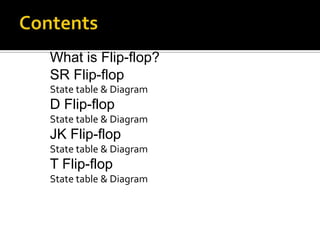
Flip flop's state tables & diagrams
state diagrams of flip flops - SlideShare state diagrams of flip flops 1. ByUnsaShakir 2. A state diagram is a diagram used in computer science to describe the behavior of a system considering all the possible states of an object when an event occurs. State diagrams are often used to represent the dynamic behavior of systems. The circles in a state diagram correspon

Designing Sequential Circuits using D-FLIP FLOPS | All About ...
What is state diagram in flip flop? - handlebar-online.com What does a D flip flop do? What is state diagram in flip flop? In addition to graphical symbols, tables or equations, flip-flops can also be represented graphically by a state diagram. In this diagram, a state is represented by a circle, and the transition between states is indicated by directed lines (or arcs) connecting the circles.
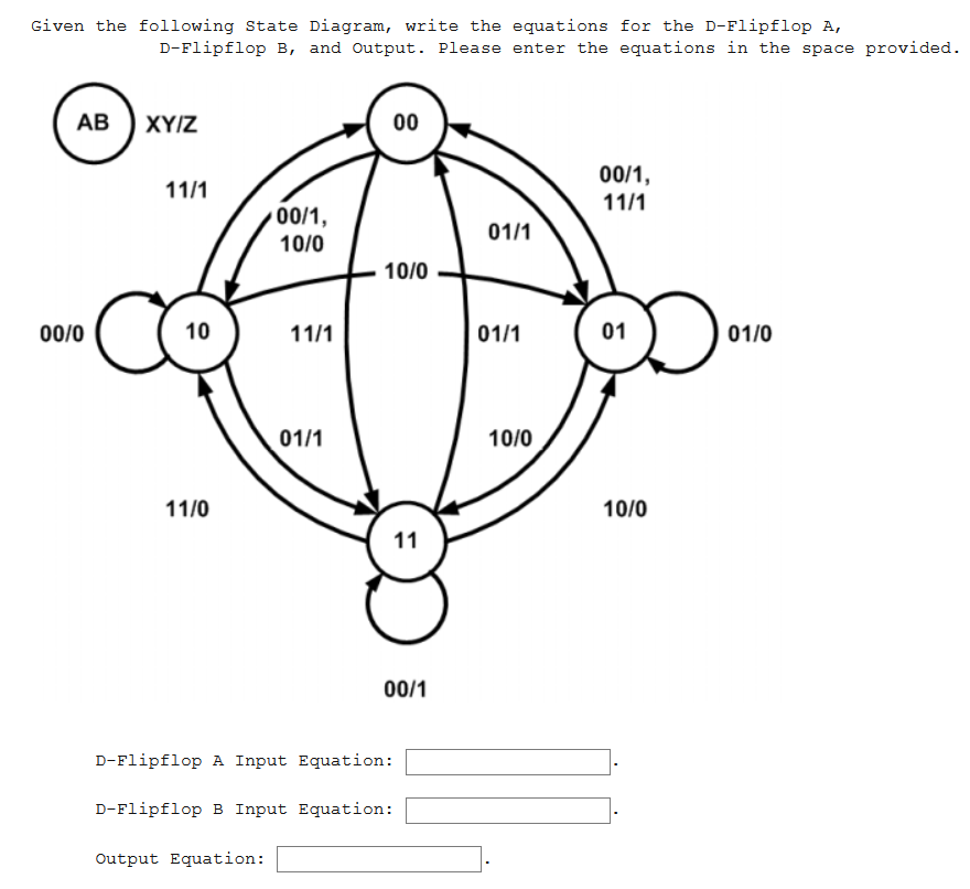
Solved Given the following State Diagram, write the | Chegg.com
D Flip-Flop Circuit Diagram: Working & Truth Table Explained Sep 27, 2017 · D Flip-Flop Circuit Diagram and Explanation: Here we have used IC HEF4013BP for demonstrating D Flip Flop Circuit, which has Two D type Flip flops inside. The IC HEF4013BP power source V DD ranges from 0 to 18V and the data is available in the datasheet. Below snapshot shows it. Since we have used LED at output, the source has been limited to 5V.
Sequential Circuits Introduction Index I Introduction II D
State Diagram For Jk Flip Flop - U Wiring The JK flip flop is a universal flip flop having two inputs J and K. Circuit State Diagram State Table State. Before clock Next state. If J and K are different then the output Q takes the value of J at the next clock edge. Draw state table 5. One D flip-flop for each state bit. J0 X Y K0 X Y Y Q1 J1 X YQ0 K1 Y Q0 X Y Q0.

Digital Circuits and Systems - Circuits i Sistemes Digitals ...
PDF Circuits with Flip-Flop = Sequential Circuit Circuit ... Circuit, State Diagram, State Table State: flip-flop output combination Present state: before clock Next state: after clock State transition <= clock 1 flip-flop => 2 states 2 flip-flops => 4 states 3 flip3 flip-flops => 8 statesflops => 8 states 4 flip-flops => 16 states
Flip flop's state tables & diagrams
What is state diagram of d flip flop? - Answers state diagram of d flip flop is same as applied input it means. >if you are going to 0 to 0 than Qn =0 >if you are going to 0 to 1 than Qn= 1 >if you are going to 1 to 0 than Qn = 0 >if you are ...

Draw a Moore-type state diagram and design a synchrono ...
For the state diagram below, if a T flip flop and a D ... Transcribed image text: For the state diagram below, if a T flip flop and a D flip flop are used, then what is the equation for the input of T and D flip flop? (Assume T and D is the input of T flip flop and D flip flop respectively, Qt and Qd are the outputs of T flip flop and D flip flop respectively, and A, B are the external inputs). 00 XX 1 01 10 01,1X Dxx 00 1 0 XX 11 01,1X D 00 1 Please ...
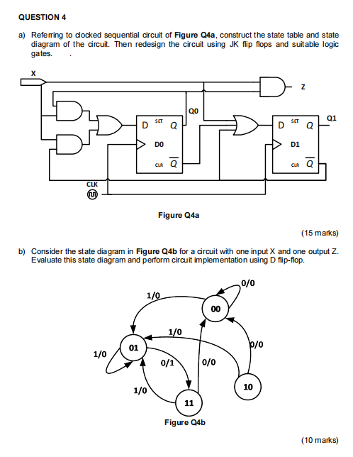
Solved QUESTION 4 a) Referring to clocked sequential circuit ...
Verilog code for D flip-flop - All modeling styles It applies to flip flops too. Hence, we will include a clear pin that forces the flip flop to a state where Q = 0 and Q' = 1 despite whatever input we provide at the D input. This clear input becomes handy when we tie up multiple flip flops to build counters, shift registers, etc. Behavioral Modeling of D flip flop with Synchronous Clear
Virtual Labs
Circuit, State Diagram, State Table Circuits with Flip-Flop ...

Solved (4) Given the state diagram below, generate the state ...
24 Finite State Machines.html

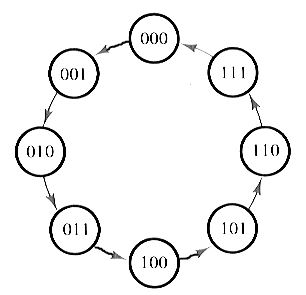
State diagram and implementation of a six bit ring counter ...
Synchronous Sequential Logic - ppt video online download
Conversion of S-R Flip-Flop into D Flip-Flop - GeeksforGeeks
Solved Boolean Flip Flops. Given this state diagram: | Chegg.com
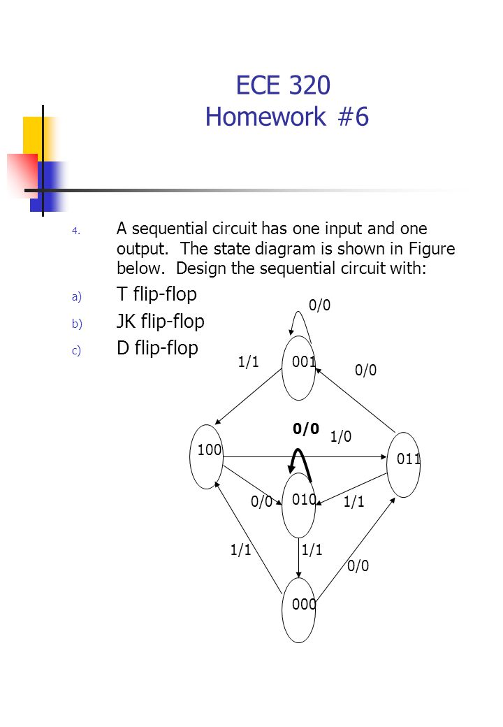
ECE 320 Homework #6 Derive the state table and state diagram ...
VHDL Code for Flipflop - D,JK,SR,T
state machines - Desiging FSM using D flip flop - Electrical ...
Solved] plz help me as far as posibol plz | Course Hero

D-type Flip Flop Counter or Delay Flip-flop

Answered: Design an Octal Counter with D… | bartleby

State Table Of Sequential Circuit Using D Flip Flop(हिन्दी )
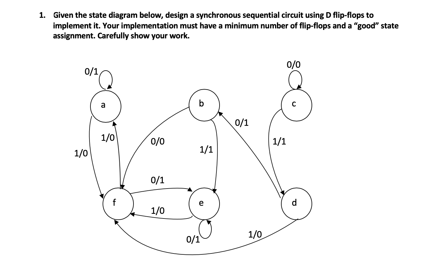
Solved 1. Given the state diagram below, design a | Chegg.com
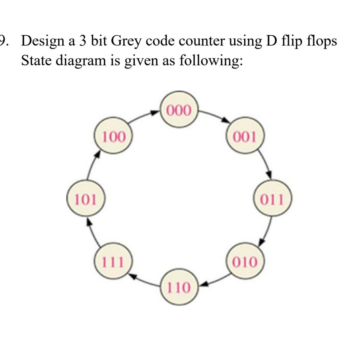
Solved 9. Design a 3 bit Grey code counter using D flip ...
state diagrams of flip flops
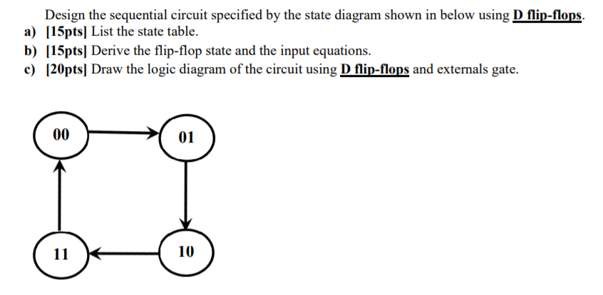
Solved Design the sequential circuit specified by the state ...
PPT - ELEC1700 Computer Engineering 1 Week 9 Monday lecture ...
state diagrams of flip flops

State diagrams and flip flops

Analysis of Clocked Sequential Circuits (with D Flip Flop)
SR-to-D and SR-to-T Flip-Flop Conversions - Technical Articles
Digital Flip-Flops - SR, D, JK and T Flip-Flops - Sequential ...
Virtual Labs
Circuit, State Diagram, State Table Circuits with Flip-Flop ...
0 Response to "42 d flip flop state diagram"
Post a Comment