45 refrigeration cycle diagram pdf
PDF Motor Vehicle Air Conditioning (MVAC) Motor Vehicle Air Conditioning (MVAC) System operation and the refrigerant cycle At Sea level ‐water boils at 212⁰ F ‐R‐134a boils at ‐15⁰ F At Sea level ‐ ‐R‐134a boils at ‐15⁰ F At 30 psig ‐ ‐R‐134a boils at 35⁰ The Pressure of theF evaporator will control it's Temperature PDF P-h Diagram -master Diagram of Refrigeration P-H DIAGRAM -MASTER DIAGRAM OF REFRIGERATION PRINCIPLE OF OPERATION-CARNOT CYCLE . The normal Carnot cycle uses heat energy and delivers mechanical work . In the early 1820s, Sadi Carnot (1786−1832), a French engineer, became interested in improving the efficiencies of practical heat engines. In 1824, his studies led him to
PDF Refrigeration technology - 西门子中国 5.The compression refrigeration cycle on the h-log p diagram 6. Heat pump technology 7. Ice banks 4. 7.6 Ice bank control 84 7.6.1 Control of the glycol-water mixture's temperature 84 7.6.2 Control of the diverting valve according to operating mode85 7.6.3 Ice bank charging control 85

Refrigeration cycle diagram pdf
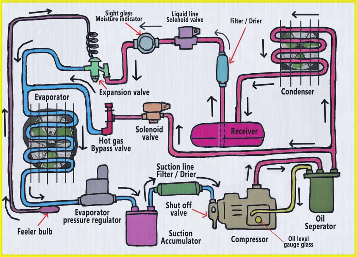
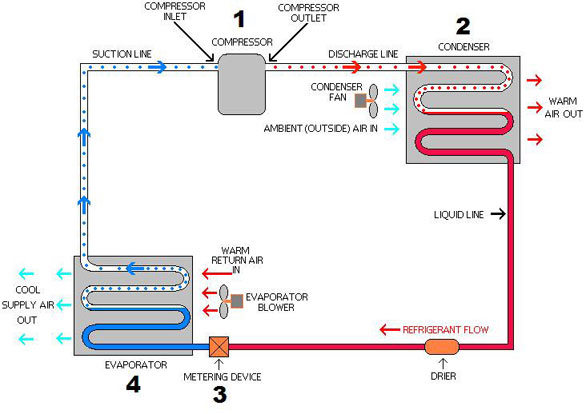
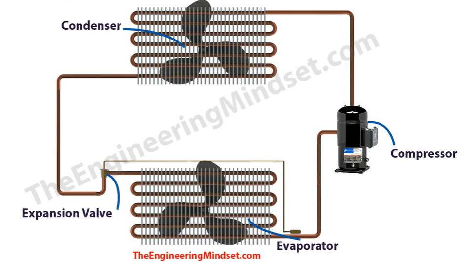
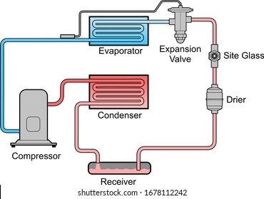
PDF How does basic refrigeration cycle work? This is how the refrigeration cycle diagram looks: Yeah, it seems complicated at first, but it will be easier to understand once I have explained the refrigeration cycle diagram section by section. It important to understand the basic refrigeration cycle, to comprehend what is going on within the air conditioner units, we cannot see it. PDF Commercial Refrigeration Temperature & Defrost Control and ... Provides energy savings during refrigeration off-cycle ... o Initiates off-cycle/defrosts in response to drop in suction temp/pressure o Provides indirect space temperature control o Does provide feedback regarding defrost effectiveness o Can be difficult to dial-in PDF Unit 5: Refrigeration Systems - IGNOU Figure 5.3 T-S Diagram of Ideal Vapour Compression Refrigeration Cycle 5.6 PRESSURE ENTHALPY DIAGRAM The refrigeration industry did not always have the analysis tools that are available today. For many decades, the manufacturers and technicians relied on the
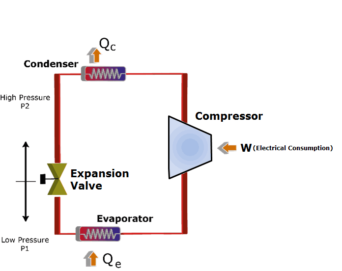
Refrigeration cycle diagram pdf. What is Refrigeration Cycle? Explanation, Components ... Explanation, Components & Diagram. Vapour compression refrigeration system runs on 'vapour compression cycle', in which, a suitable working substance, termed as 'refrigerant', is used. For example: Freon compounds such as R-1, R-12, R-22 etc. Carbon dioxide (C0 2 ), Ammonia (R-717) and Water (R-718) are also used as refrigerants in some ... PDF Refrigeration Cycle REFRIGERATION CYCLE The refrigeration cycle shown here is a typical R-22 system. The compressor and thermal expansion valve are the boundaries for the high and low sides. It's important to understand that a refrigerator is a heat engine that operates in reverse. Energy is transferred from a low level to high level, which is contrary to PDF Refrigeration Cycle - Landmark University Fig. 11. T-S diagram for Wet Vapour Compression Cycle Fig. 12. P-h diagram for Wet Vapour Compression Cycle In this cycle, enthalpy at state 2 is found with the help of dryness fraction at this point (2). The dryness fraction at points 1 and 2 may be obtained by equating entropies at state 1 and 2. C.O.P = = PDF Pressure-enthalpy Charts and Their Use - Rses Figure 4 is a pressure-enthalpy diagram of a typical refrigeration cycle in a system with one pound of HFC-134a. It uses (for this example) evaporating and condensing temperatures of 0°F and 120°F. Points on the diagram are labeled to correspond to locations of equipment in the system. Each step of the cycle can be approached separately.
PDF Refrigeration Basics and LNG - University of Oklahoma Figure 2-4: Wet refrigeration Cycle - The expander has been substituted by a throttling valve. If an expander had been used the line from d to a would be a vertical line. This is also done for mechanical reasons. The refrigeration cycles can also be represented in a P-H diagram. Figure 2-5: P-H diagram representation of a dry refrigeration cycle PDF Basic Knowledge Thermodynamics of the Refrigeration Cycle The log p-h diagram for refrigerant The refrigeration cycle For operating media which can have different phases, such as water or refrigerant, theT-sdiagram looks different. It has an area on the left (grey),in which the operating medium is liquid and supercooled. In the centre(blue) there is a mixture of steam and liquid, the wet steam. PDF Chapter 11 REFRIGERATION CYCLES REFRIGERATION CYCLE The vapor-compression refrigeration cycle is the ideal model for refrigeration systems. Unlike the reversed Carnot cycle, the refrigerant is vaporized completely before it is compressed and the turbine is replaced with a throttling device. 5 Schematic and T-s diagram for the ideal vapor-compression refrigeration cycle. (PDF) Refrigeration Cycles 6.8 Steam Jet Refrigeration ... Indian Institute of Technology Madras fRefrigeration Cycles Prof. U.S.P. Shet , Prof. T. Sundararajan and Prof. J.M . Mallikarjuna Advantages: a) It is flexible in operation; cooling capacity can be easily and quickly changed. b) It has no moving parts as such it is vibration free. c) It can be installed out of doors.
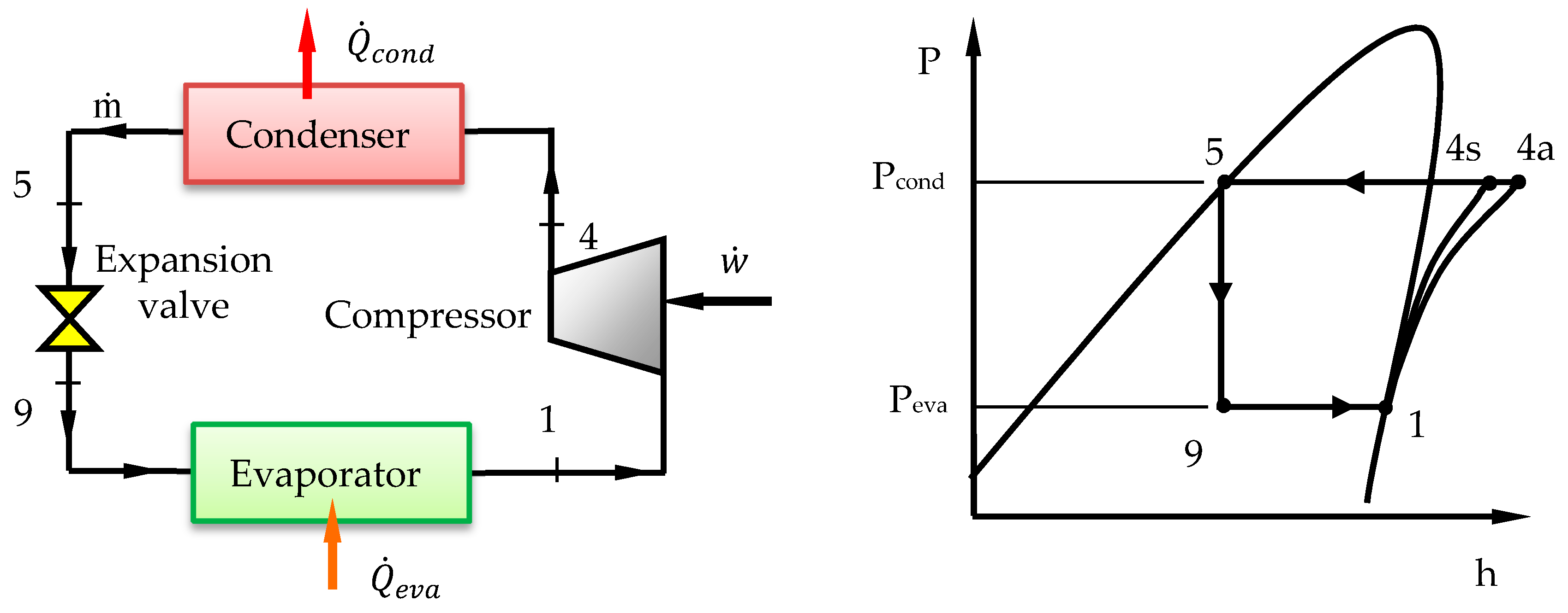
PDF Vapor Compression Refrigeration Cycle Figure 6- Pressure-enthalpy diagram of an ideal refrigeration cycle. Figure 7- L F D diagram of a real refrigeration cycle. To calculate the refrigerating capacity, i.e., heat transfer from low temperature source, 3 6 Å, the refrigerant mass flow rate I 6 should be known beforehand. The specific volume å for the refrigerant is read from the L The Refrigeration Cycle - In easy to understand ... In this final diagram of the refrigeration cycle we have introduced 3 new terms: Superheated, Saturated & subcooled. SUPERHEAT - Is an amount of heat added to refrigerant vapour beyond its boiling point. This ensures the refrigerant is in a gas state with no liquid present. PDF Chapter 10: Refrigeration Cycles - Saylor Academy Shown below are the cyclic refrigeration device operating between two constant temperature reservoirs and the T-sdiagram for the working fluid when the reversed Carnot cycle is used. Recall that in the Carnot cycle heat transfers take place at constant temperature. If our interest is the cooling load, the cycle is called the Carnot refrigerator. PDF Refrigeration Cycle - Simon Fraser University Actual Vapor‐Compression Refrigeration Cycle Fig. 5-4: T-s diagram for actual vapor-compression cycle. Most of the differences between the ideal and the actual cycles are because of the irreversibilities in various components which are: 1-In practice, the refrigerant enters the compressor at state 1, slightly superheated vapor, ...
Schematic diagram of a simple refrigeration cycle | Download ...
PDF Case 1: The Basics of Refrigeration Cycle P.H. Diagram ... Figure 1-6 Refrigeration Cycle P-H Diagram Image Figure 1-7 Properties of Refrigerant at -20℉ Figure 1-8 Properties of the Refrigerant at 105℉ H 1is the saturated suction of the compressor at -20ºF. at no losses. H 2is the compressor discharge point at no losses. H 5is the saturated liquid at 105ºF condensing temperature.
![PDF] Absorption Heat Pump/Refrigeration System Utilizing ...](https://asset-pdf.scinapse.io/prod/2133196693/figures/figure-1.jpg)
PDF] Absorption Heat Pump/Refrigeration System Utilizing ...
PDF Chapter 10 Refrigeration & Heat Pump Cycles (Systems) • If a single refrigeration cycle could be used for the overall temperature range, this would be represented by the cycle 1->a->7->b->1. • Two significant effects are apparent from the Ts diagram: (1) for the single cycle - the compressor work is increase by area 2->a->6->5->2. (2) there is a decrease in the refrigeration capacity when a ...
Vapor Compression System | Compression Cycle | ARANER
PDF Refrigeration: Theory And Applications 5.1 Evaporative cooling 72 5.2 Peltier-Seebeck effect (thermoelectric devices) 73 5.3 Magneto-Calorific Effect (Magnetic Refrigeration) 75 5.4 Thermo-acoustic effect (acoustic refrigeration) 76 5.6 Summary of Chapter 5 78 5.7 Further Reading 78 Download free eBooks at bookboon.com Click on the ad to read more

Vapour Absorption Refrigeration system | Working ,Diagram
Design of Vapor-Compression Refrigeration Cycles Figure 1: Vapor-Compression Refrigeration Cycle T-s diagram Below is a possible CyclePad design of a refrigeration cycle. The layout shown below is a clickable image. To jump to the part of this page that details the assumptions of a particular device or statepoint, just click on it.
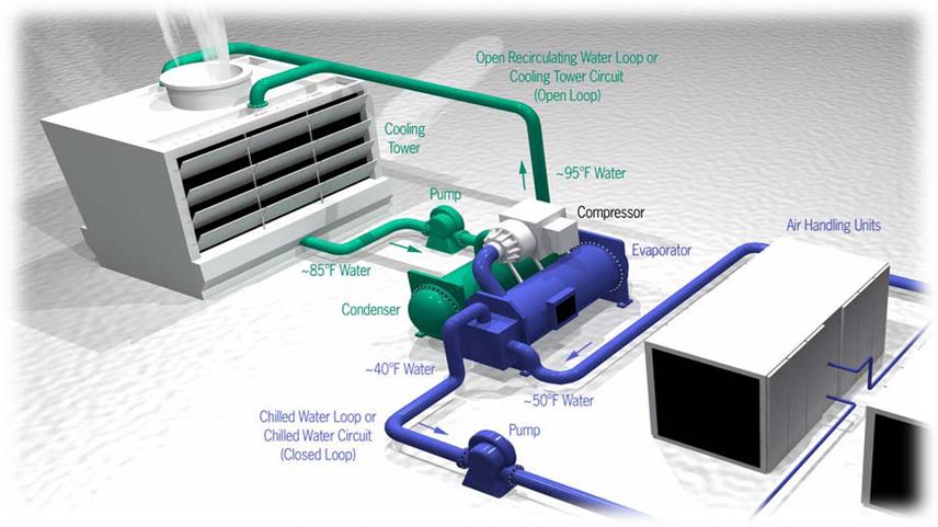
Types of Chiller and Refrigeration Cycles
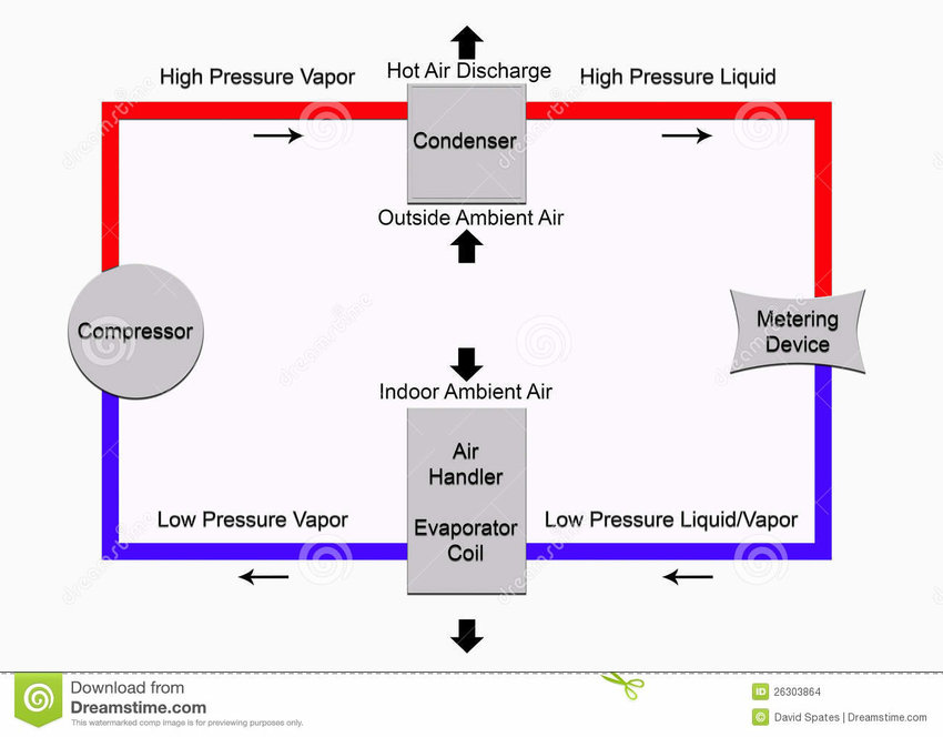
What is Refrigeration Cycle? Basic, Diagram & Explanation ... The refrigeration cycle is a thermodynamic cycle to generate refrigerating effect with the use of an evaporator, compressor, condenser & expansion valve. This process is basically a thermodynamic process where working fluid absorbs heat from the surrounding at low temperature and reject the heat to the atmosphere at a higher temperature.
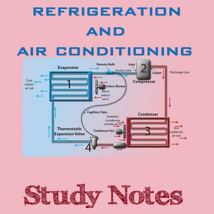
Refrigeration & Air Conditioning (RAC) Study Notes ...
PDF Refrigeration Cycle Tutorial - University of Oklahoma Figure 4: Wet refrigeration Cycle - The expander has been substituted by a throttling valve. If an expander had been used the line from d to a would be a vertical line. This is also done for mechanical reasons. The refrigeration cycles can also be represented in a P-H diagram. Figure 5: P-H diagram representation of a dry refrigeration cycle

Advantages and Disadvantages of Vapor Compression ...
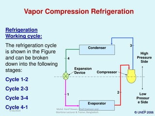
PDF UNIT 2 REFRIGERATION CYCLE Refrigeration Cycle Refrigeration cycle is the basis of all refrigeration systems. So refrigeration cycle should be known to understand the refrigeration system. Some basic refrigeration cycles are discussed here through different diagrams. 2.2 VAPOUR COMPRESSION CYCLE Vapour compression cycle is an improved type of air refrigeration cycle in which a suitable ...

Draw a neat sketch of vapour compression refrigeration cycle ...
PDF Lab #8 Refrigeration - NCSU Pressure-Enthalpy Diagram for R-12 Lines of Constant Values for Various Parameters Sub-Cooled Liquid Liquid-Vapor Mixture Superheated Vapor Const. Pressure Const. Enthalpy Const. Temp. Const. Entropy Const. Dryness Fraction Specific Enthalpy (kJ/kg) Absolute Pressure (bar) Pressure-Enthalpy Diagram for R-12 Evaporation
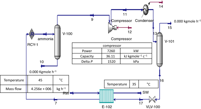
Performance analysis and development of a refrigeration cycle ...
PDF Refrigeration - NCSU Purpose of Refrigeration • To slow down rates of detrimental reactions - Microbial spoilage - Enzyme activity - Nutrient loss - Sensorial changes Guideline: Generally, rates of reactions double for every 10 °C rise in temperature 3 Examples/Applications of Cooling • Cooling engine of a car - Coolant/water
Processes | Free Full-Text | Performance Analysis and Working ...
PDF Refrigeration 101 - US EPA 1. Heat flows from high energy levels to 1 a lower energy level. 2. Heat will not flow without a 2 eat ot o t out a temperature difference 33. The greater the temperature difference, the faster the energy will flow. Radiation Ht Fl Convection HHeaeattows ThreeThree Ways Conduction Conduction

Refrigeration: Definition, Types, Classification of ...
PDF Unit 5: Refrigeration Systems - IGNOU Figure 5.3 T-S Diagram of Ideal Vapour Compression Refrigeration Cycle 5.6 PRESSURE ENTHALPY DIAGRAM The refrigeration industry did not always have the analysis tools that are available today. For many decades, the manufacturers and technicians relied on the
Marine Refrigeration and Air Conditioning
PDF Commercial Refrigeration Temperature & Defrost Control and ... Provides energy savings during refrigeration off-cycle ... o Initiates off-cycle/defrosts in response to drop in suction temp/pressure o Provides indirect space temperature control o Does provide feedback regarding defrost effectiveness o Can be difficult to dial-in
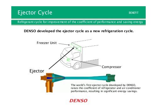
Ejector Cycle(PDF:124KB)
PDF How does basic refrigeration cycle work? This is how the refrigeration cycle diagram looks: Yeah, it seems complicated at first, but it will be easier to understand once I have explained the refrigeration cycle diagram section by section. It important to understand the basic refrigeration cycle, to comprehend what is going on within the air conditioner units, we cannot see it.

Electrolux Refrigeration System Overview (With Diagram ...
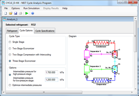
CYCLE_D-HX: NIST Vapor Compression Cycle Model Accounting for ...
15 Major Components and Controls of Refrigeration System ...

Refrigeration System - an overview | ScienceDirect Topics

Explain Marine Refrigeration System With simple Diagram
Vapour Compression Refrigeration Cycle: Components, Working ...
Exergy characteristics of R404A indirect refrigeration system ...

Electrolux Refrigeration System - Mechanical Walkins

Chapter 9: Carbon Dioxide (R744) The New Refrigerant (updated ...
Beginner 1. Basic Refrigeration Cycle.pptx

Cascade refrigeration - Wikipedia

Seminar On Absorption Refrigeration System PDF Report Download

Planning and engineering data 3. Fish freezing - 3. Processes ...
Schematic diagram of domestic refrigerator. | Download ...

Transcritical CO2 (R744) Refrigeration Cycle - MATLAB & Simulink
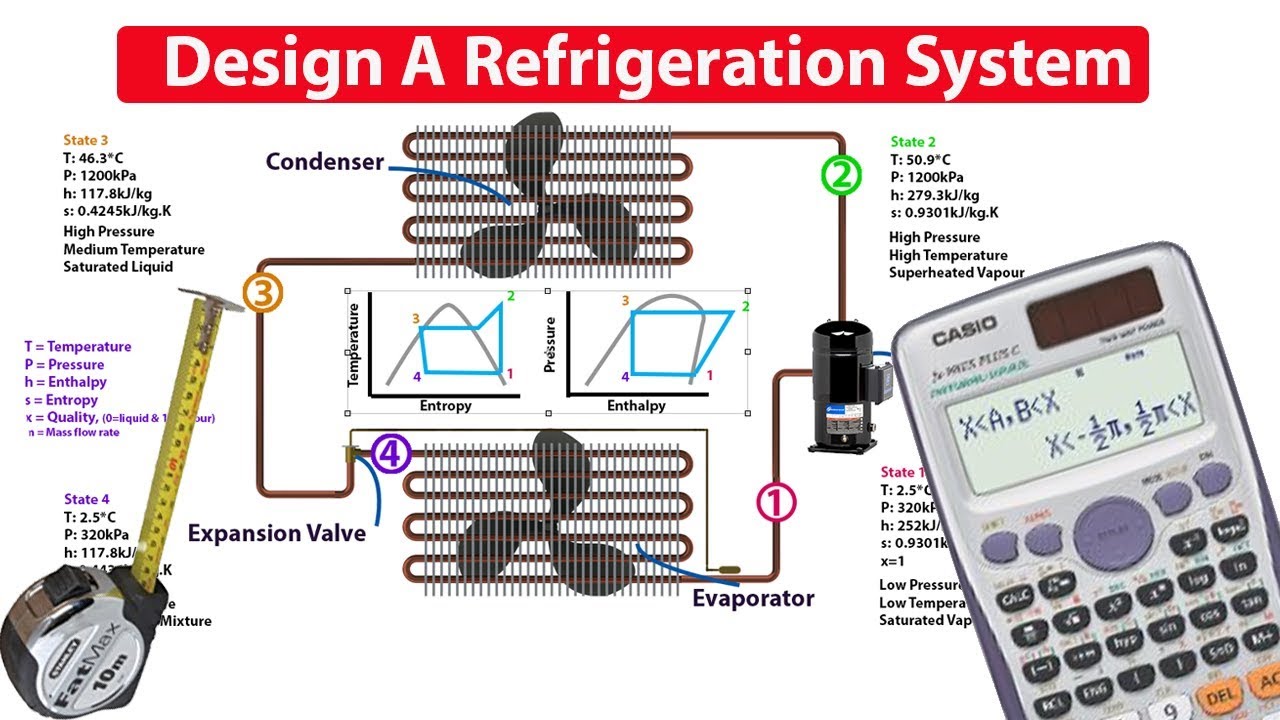
Design a Refrigeration System - The Engineering Mindset
Energies | Free Full-Text | Performance Optimizations of the ...
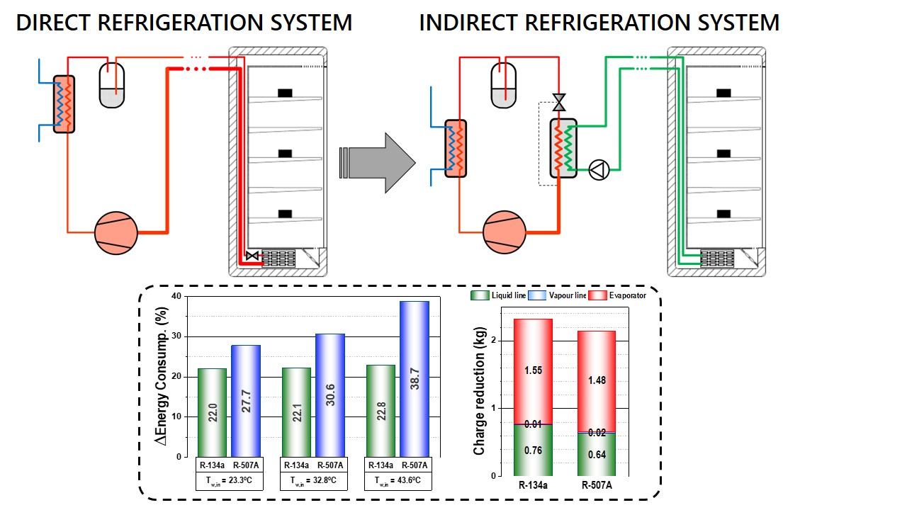
Applied Sciences | Free Full-Text | Conversion of a Direct to ...

Schematic for a two-stage cascade refrigeration system ...
Chapter 10: Refrigeration Cycles

Conception of an Absorption Refrigerating System Operating at ...

Refrigeration System - an overview | ScienceDirect Topics

A basic ideal refrigeration cycle, as shown in Figure 7.5, is ...
The refrigeration cycle explained in plain english.
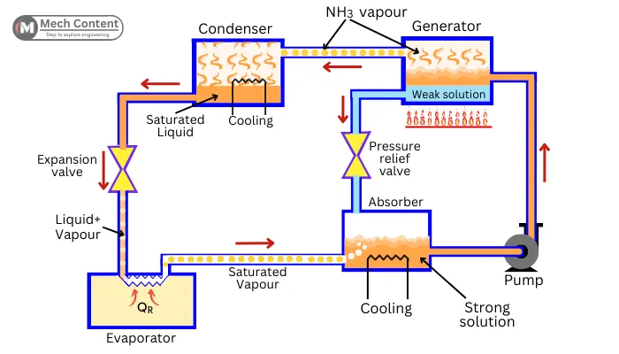
Vapour absorption refrigeration system: Definition, Diagram ...
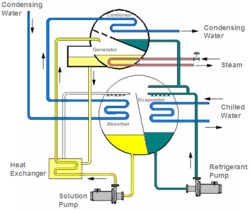
Absorption Chiller Pump
Design a Refrigeration System - The Engineering Mindset
PDF) basic-refrigeration-cycle
2d Diagram Air Conditioning Refrigeration Cycle Stock ...
Basic Refrigeration Cycle
Refrigeration Cycle Diagram Vector Illustration Stock Vector ...

Vapour Absorption Refrigeration System - Components and Working
0 Response to "45 refrigeration cycle diagram pdf"
Post a Comment