43 a diagram that shows the messages between an actor and the system is called a(n) _______.
Actions are performed with lines that extend between these lifelines. When an action line is connected to a lifeline it shows the interaction between the actor or system. Messages will often appear at the top or bottom of a system sequence diagram to illustrate the action in detail. 26. Answer : (d) Reason: Component diagram models the physical components of the system. 27. Answer : (c) Reason: Stereo types represent the built-in extensibility mechanism of UML. 28. Answer : (a) Reason: Noun-Phrase Method and (RC Approach are used to identify classes.
_____ diagrams depict the interaction between an actor and the system fro a use case scenario System Sequence ______ diagrams graphically depict how objects interact with each other via messages in execution of use case or operation.

A diagram that shows the messages between an actor and the system is called a(n) _______.
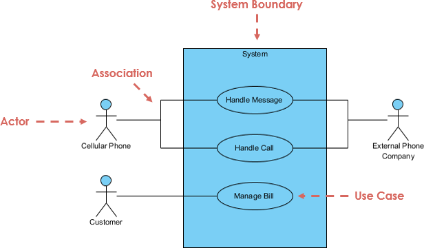
A system sequence diagram is, as the name suggests, a type of sequence diagram in UML. These charts show the details of events that are generated by actors from outside the system. A use case diagramis ';a diagram that shows the relationshipsamong actors and use cases within a system. 'Use case diagrams are often used to: UML is the modeling toolkit that you can use to build your diagrams. Use cases are represented with a labeled oval shape. Stick figures represent actors in the process, and the actor's participation in the system is modeled with a line between the actor and use case. To depict the system boundary, draw a box around the use case itself. 15. In a sequence diagram, a(n) message is identified by a line showing direction that runs between two objects. 16. The focus indicates when an object sends or receives a message. 17. A(n) state transition diagram shows how an object changes from one state to another, depending on events that affect the object. 18.
A diagram that shows the messages between an actor and the system is called a(n) _______.. Questions and answers - MCQ with explanation on Computer Science subjects like System Architecture, Introduction to Management, Math For Computer Science, DBMS, C Programming, System Analysis and Design, Data Structure and Algorithm Analysis, OOP and Java, Client Server Application Development, Data Communication and Computer Networks, OS, MIS, Software Engineering, AI, Web Technology and many ... 11. _____ diagrams are used to illustrate data structures, and the static snapshots of instances of the things found in the class diagrams. a. Use case b. Object c. Collaboration d. Sequence. 12. Object diagram is used to show the _____ design view of a system. a. static b. dynamic c. logical d. process Sequence diagrams emphasize the time ordering of messages. Sequence diagrams can be used to translate the use case scenario into a visual tool for systems analysis. The initial sequence diagram used in systems analysis shows the actors and classes in the system and the interactions between them for a specific process. A diagram that shows the messages between an actor and the system is called a(n) _____. system sequence diagram An arrow on a system sequence diagram is used to depict a(n) what?
Reason: Gane and Sarson, Shlaer Mellor and Extreme Programming are not object oriented Methodologies. 292. Answer : (a) Reason: Use Case is a construct that helps analysts to work with users to determine system usage. 293. Answer : (c) Reason: 1..2 represents 1 or 2 but not 1-2. Association Between Actor and Use Case. This one is straightforward and present in every use case diagram. Few things to note. An actor must be associated with at least one use case. An actor can be associated with multiple use cases. Multiple actors can be associated with a single use case. UML Sequence Diagrams are interaction diagrams that detail how operations are carried out. They capture the interaction between objects in the context of a collaboration. Sequence Diagrams are time focus and they show the order of the interaction visually by using the vertical axis of the diagram to represent time what messages are sent and when. Collaboration diagrams (known as Communication Diagram in UML 2.x) are used to show how objects interact to perform the behavior of a particular use case, or a part of a use case.Along with sequence diagrams, collaboration are used by designers to define and clarify the roles of the objects that perform a particular flow of events of a use case.
• Sequence diagram: an “interaction diagram” that models a single scenario executing in a system • 2nd most used UML diagram (behind class diagram) • Shows what messages are sent and when • Relating UML diagrams to other design artifacts: • CRC cards → class diagrams • Use cases → sequence diagrams cases describe interactions between a system and external actors; sequence diagrams add more information to these by showing interactions between system objects. • Structural models show the organization and architecture of a system. Class diagrams are used to define the static structure of classes in a system and their associations. Which of the following best describes a use case ? A. It is text describing in detail one flow of events through a real situation. B. it is the system specification problem statement. C. it is text which describes the dialogue between actors and the system. D. a diagram drawn to illustrate how cases and actors interact by sending stimuli to one ... a) Use case diagram is a dynamic model of interaction between actors and product in a use case b) Use case Description is a static model of use case supported by a product c) All of the mentioned d) None of the mentioned Answer:D. 14. A UML diagram that facilitates requirements gathering and interacts between system and external users, is called as
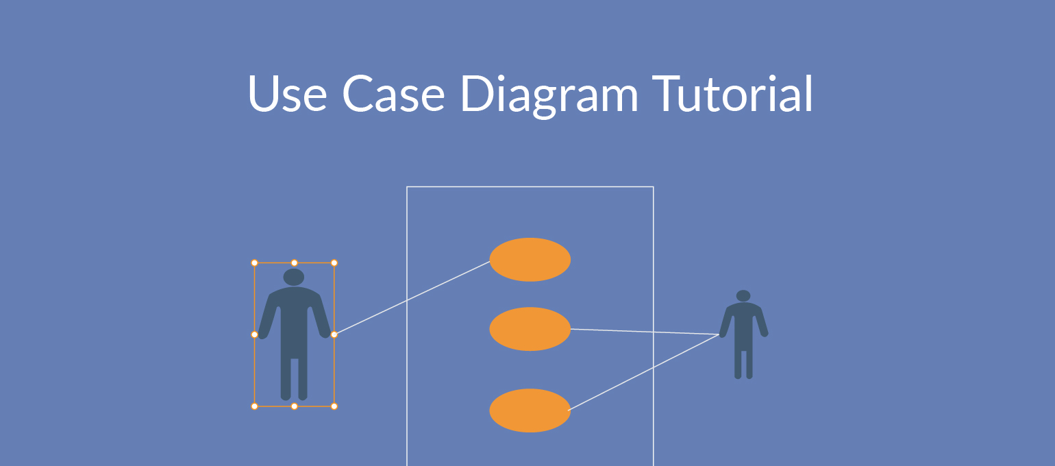
Use case diagram is a behavioral UML diagram type and frequently used to analyze various systems. They enable you to visualize the different types of roles in a system and how those roles interact with the system. This use case diagram tutorial will cover the following topics and help you create use cases better. Importance of use case diagrams.

Example 1 Exam Pdf Ict2622 Mock Exam Questions 1 In A Workflow Diagram The Arrows That Cross The Center Line Are Used To Identify What Actor And Use Course Hero
Use Case Descriptions • actors - something with a behavior or role, e.g., a person, another system, organization. • scenario - a specific sequence of actions and interactions between actors and the system, a.k.a. a use case instance • use case - a collection of related success and failure scenarios, describing actors using the system to
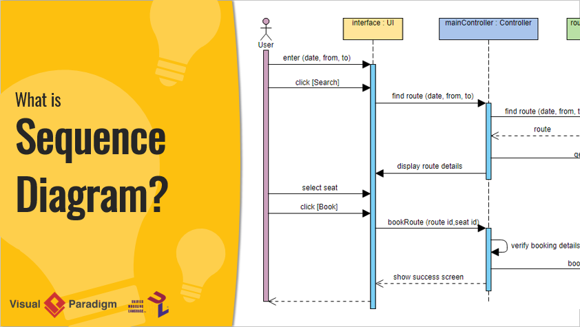
Contents of Sequence Diagrams. You can have objects and actor instances in sequence diagrams, together with messages describing how they interact. The diagram describes what takes place in the participating objects, in terms of activations, and how the objects communicate by sending messages to one another.
Communication Diagram at a Glance. In the example of the notation for a communication diagram, objects (actors in use cases) are represented by rectangles. In the example (generic communication diagram): The objects are Object1, Object2, Object..., ObjectN-1 ..., and ObjectN. Messages passed between objects are represented by labeled arrows that start with the sending object (actor) and end with the receiving object.
The diagram model that is useful to document the flow of activities on a fully developed use case description is called a (n) _______ diagram. activity . A diagram that shows the messages between an actor and the system is called a (n) _______. system sequence diagram.
The collaboration diagram is used to show the relationship between the objects in a system. Both the sequence and the collaboration diagrams represent the same information but differently. Instead of showing the flow of messages, it depicts the architecture of the object residing in the system as it is based on object-oriented programming.
An object, such as a bank account, can have a specific attribute called a(n) _____ that can be active, inactive, closed, or frozen. actor In a use case, an external entity, called a(n) _____, initiates a use case by requesting the system to perform a function or process.
How many types of UML Diagrams. 5. which diagram is used to show interactions between messages are classified as? A) activity B) state chart C) collaboration D) object lifeline Answer c. 6.which diagrams are used to distribute files, libraries, and tables across topology of the hardware
The Sequence Diagram in Software Engineering shows the interaction between two lifelines as a time-ordered sequence of events. The Collaboration Diagram in UML is also called a communication diagram. The purpose of a collaboration diagram is to emphasize structural aspects of a system, i.e., how various lifelines in the system connects.
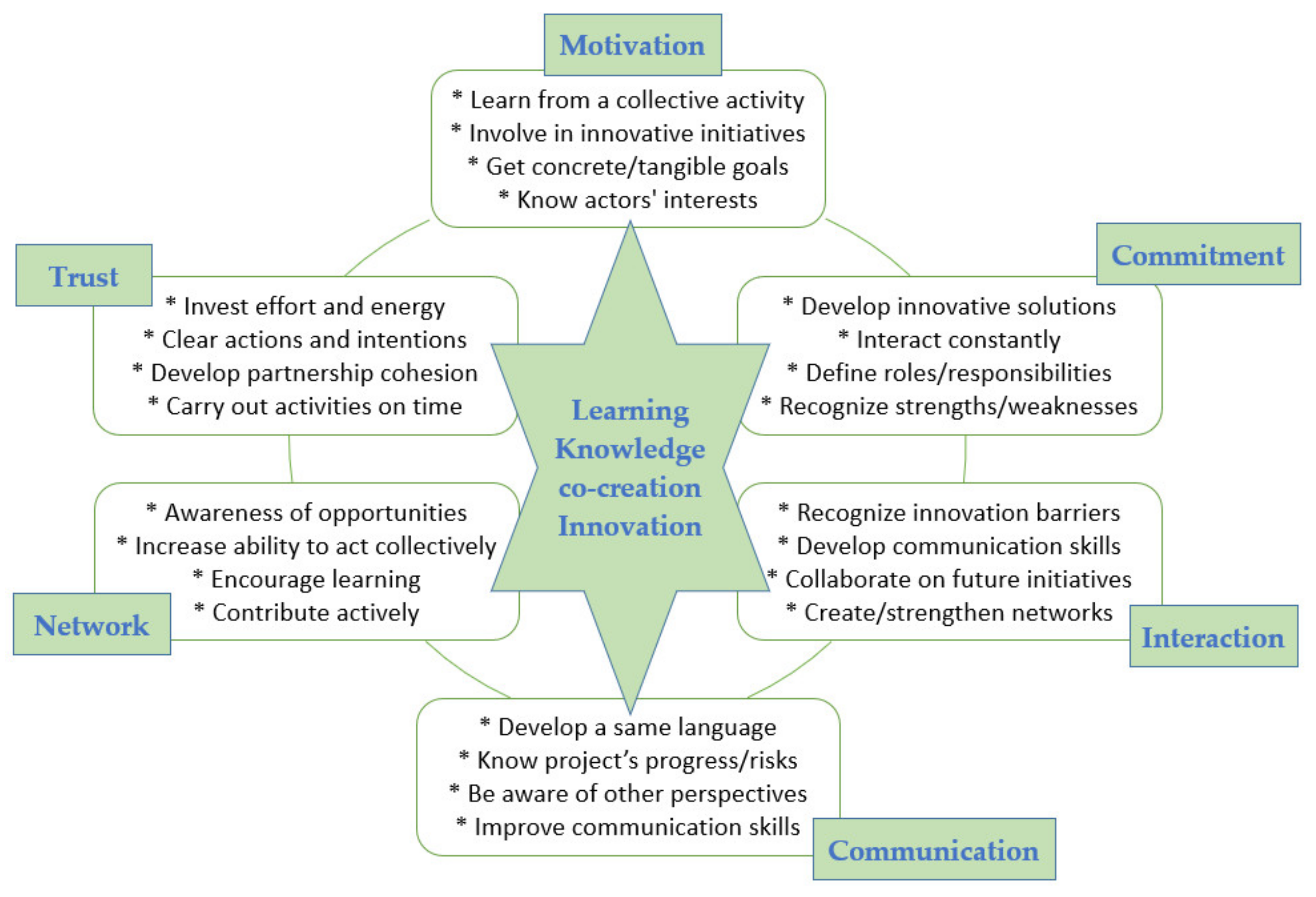
Sustainability Free Full Text Farmers Participation In Operational Groups To Foster Innovation In The Agricultural Sector An Italian Case Study Html
n a sequence diagram the message-name is usually given in what format? verb-noun. A diagram that shows the messages between an actor and the system is called a(n) _____. System Sequence Diagram. A UML diagram that shows the life of an object in states and transitions is called a(n) _____. ...
Popular beyond just the design community, this visually appealing diagram is good at showing all types of business processes. It simply reveals the structure of a system, showing the sequence of messages and interactions between actors and objects chronologically. Sequence diagrams show simple iteration and branching.
In UML 1.x, communication diagrams used to be called collaborative diagrams. As the name suggests, the main focus of this type of UML diagram is on communication between objects. Since the core components are the messages that are exchanged between objects, we can build communication diagrams the same way we would make a sequence diagram.
A diagram that shows the messages between an actor and the system is called a(n) _____. system-sequence diagram True or False: An Opt frame and a true/false condition on a message serve essentially the same purpose.
An SSD (system sequence diagram) is used to describe the messages that flow into and out of a system, i.e. between the system and the use case user. The symbols include: Stick figure for the actor. Box with object name for the system object. Vertical dashed lines for object lifelines.
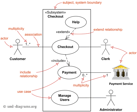
Use Case Diagrams Are Uml Diagrams Describing Units Of Useful Functionality Use Cases Performed By A System In Collaboration With External Users Actors
15. In a sequence diagram, a(n) message is identified by a line showing direction that runs between two objects. 16. The focus indicates when an object sends or receives a message. 17. A(n) state transition diagram shows how an object changes from one state to another, depending on events that affect the object. 18.
UML is the modeling toolkit that you can use to build your diagrams. Use cases are represented with a labeled oval shape. Stick figures represent actors in the process, and the actor's participation in the system is modeled with a line between the actor and use case. To depict the system boundary, draw a box around the use case itself.
A system sequence diagram is, as the name suggests, a type of sequence diagram in UML. These charts show the details of events that are generated by actors from outside the system. A use case diagramis ';a diagram that shows the relationshipsamong actors and use cases within a system. 'Use case diagrams are often used to:













0 Response to "43 a diagram that shows the messages between an actor and the system is called a(n) _______."
Post a Comment