43 project schedule network diagram
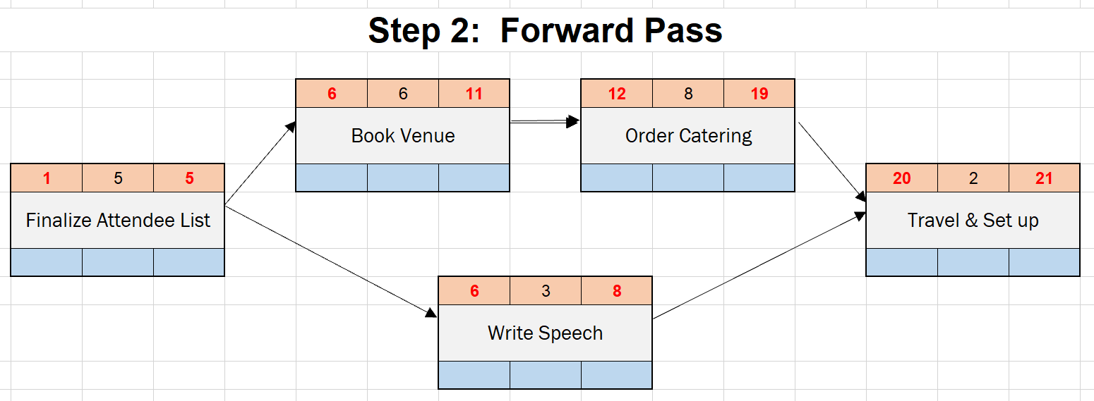
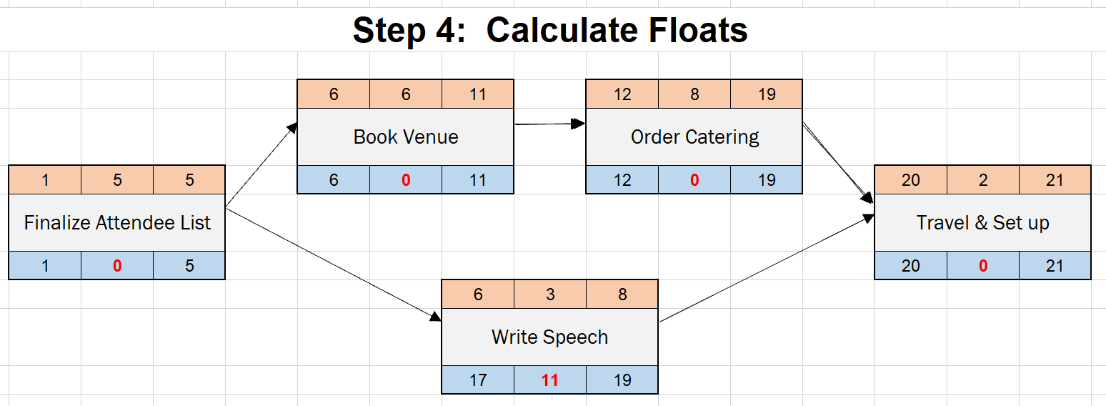
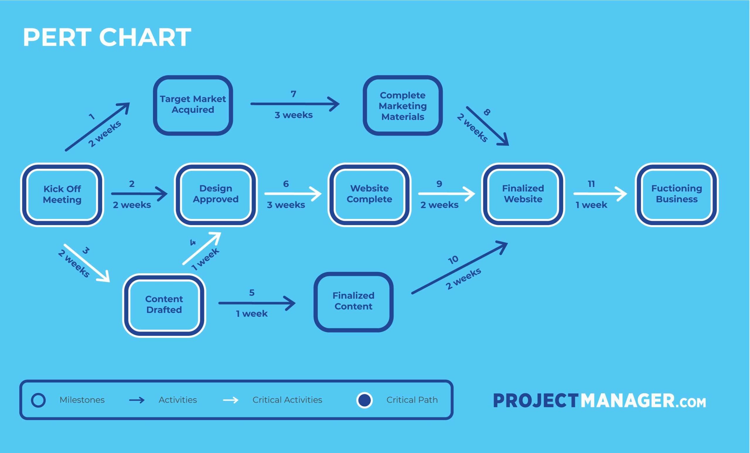
What Is a Network Diagram? A network diagram is a schematic that shows all the tasks in a project, who is responsible for them and the flow of work that is necessary to complete them. In other words, they help visualize the project schedule. Like the PERT chart, it is also made up of arrows and nodes that show the course of tasks through the life cycle of a project. Calculating Critical Path & Float for a Network Diagram Find out the length of all the paths in the network diagram The longest path is the critical path Float = EF - LF ... the duration required in the project schedule. For negative project float, the project must be crashed or fast-tracked.
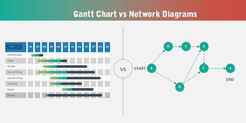
The project schedule is represented in 3 common formats in a project. Project Schedule Format #1: Network Diagram. Network Diagrams visualize the project activities in boxes with the activity IDs and show the interrelationship of activities with arrows. Network diagrams indicate if an activity will start earlier, later or at the same time with ...
Project schedule network diagram
An effective project schedule network diagram will serve as a clear and concise representation of the project. The Arrow diagram and the Precedence diagram are the two types of network diagrams that exist. In an Arrow diagram, nodes are used to depict events and arrows are used for activities, ... The project schedule network diagram captures the order in which the project activities should be scheduled to address their logical relationships. It has different intersections, generally known as nodes, that symbolize the activities, whereas the arrows show the sequence and interdependencies of these activities. A project schedule network diagram is created by (an output of) the PMI process to sequence activities. The diagram is then used in the process, develop schedule. Basically the project schedule network diagram is a way to visually portray the sequences of the activities in the project. When combined with other factors, such as activity duration estimates and resource calendars, a project ...
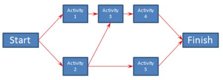
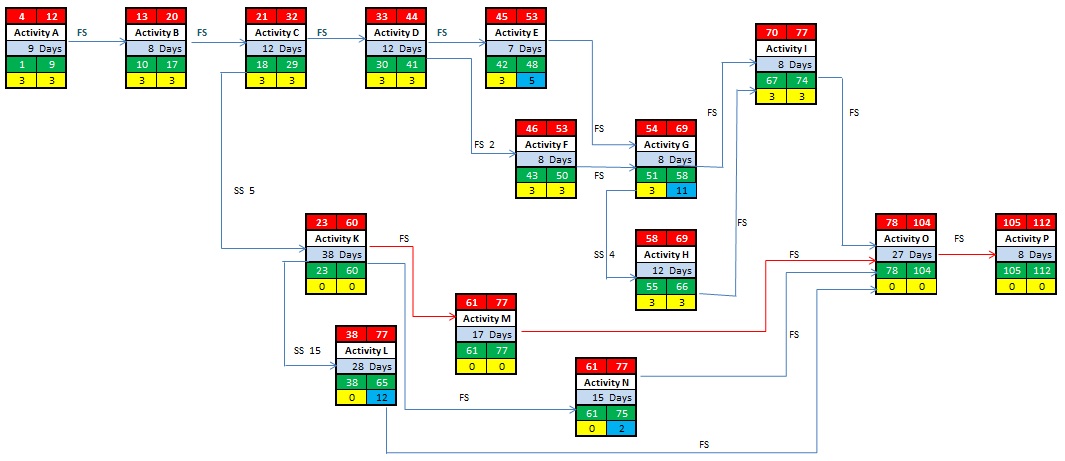
Project schedule network diagram. The project schedule network diagram is a visual representation of the activities in a project and their inter-dependency. There are two common approaches to build a network diagram. The first approach is the Precedence Diagramming Method (PDM) which is also called Activity-On-Node (AON) (Figure 1). Figure 1 Precedence Diagramming Method Example. Oct 15, 2021 — A project network diagram is a vital concept in project management, as it is the basis of your schedule and helps you allocate resources. Schedule Network of Analysis is a set of data that is researched that we seek to understand. Schedule network analysis is a technique that generates the project management schedule. It is a detailed report of how and when you execute the next step of your project. One of the more important topics to understand when planning project activities is creating network diagrams. A Schedule Network Diagram is a key part in your project Schedule planning, especially when trying to figure out the critical path and the "float" or wiggle room in your project. Below is a nice way to create a dynamic Schedule Network Diagram in Excel that updates when you update the numbers but is also able to be moved around your worksheet.
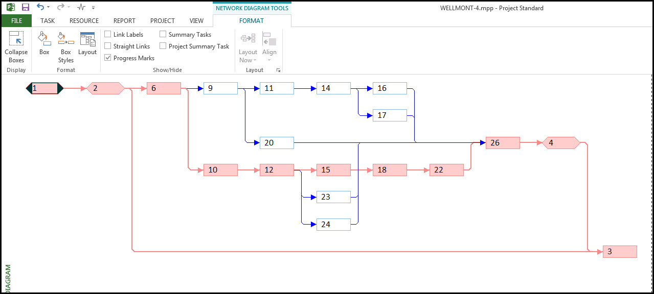
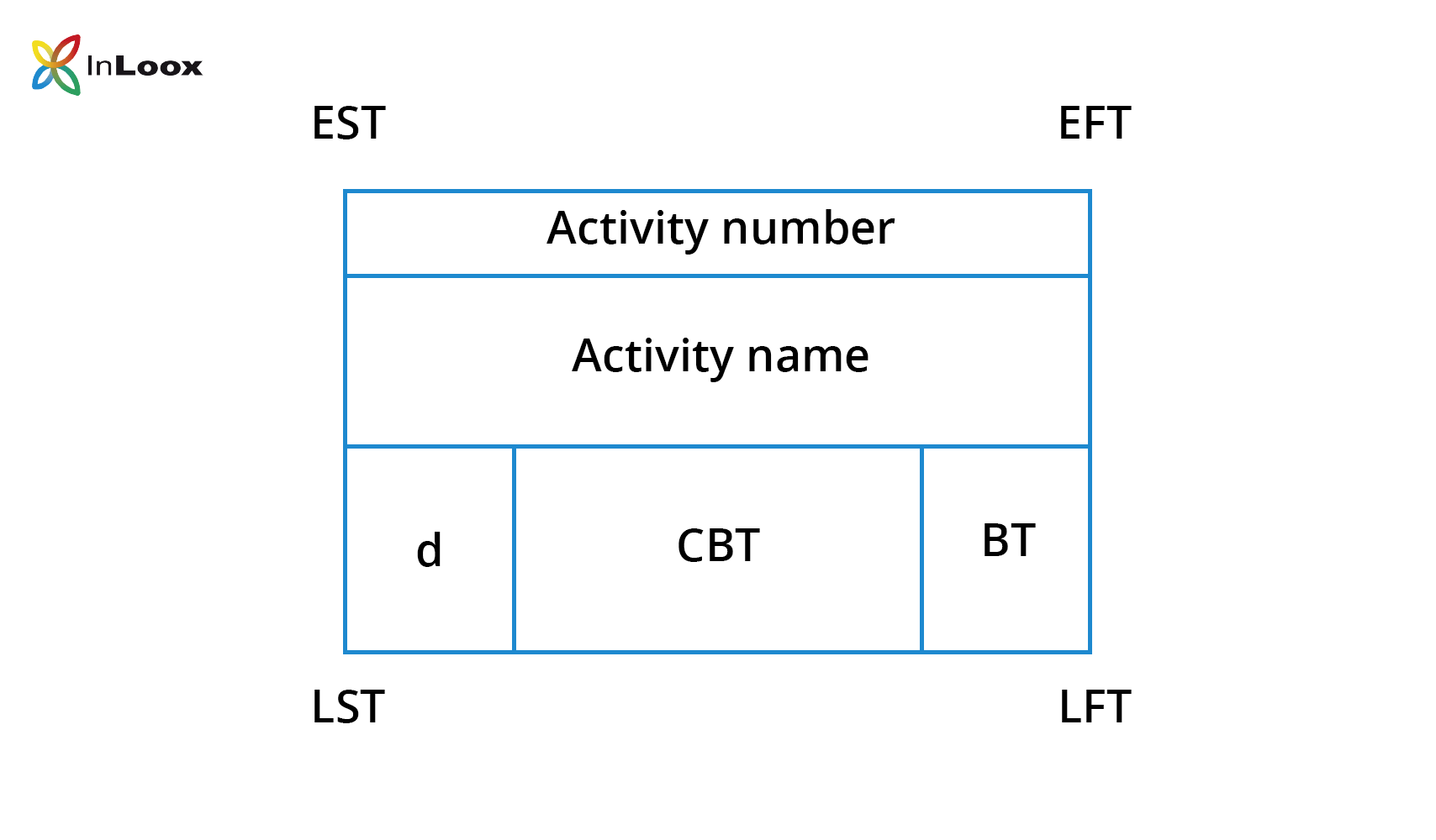
A project schedule network diagram is an output type of the process 'sequencing activities' according to PMI's Guide to the Project Management Body of Knowledge (PMBOK®, 6 th ed., ch. 6.3.3). Project schedule network diagrams show the order in which activities should be scheduled to address logical relationships between these activities. A strategy for scheduling activities in a project plan, the precedence diagramming method (PDM) is a strategy for developing a project schedule network diagram that utilizes nodes to represent activities and associates them with projectiles that illustrate the dependencies. This method is the activity-on-node (AON). • It involves linking activities to form a project network to show how different activities are ... EST, providing it finishes by the LFT the project could still finish on schedule ... Network Diagram Using MS Project Author: Anesah Project Schedule Network Diagram: This is a broad term used to encompass elements of the project from the planning stages through the completion of the project. Chronology is important so this diagram is always completed in a left to right manner.
The project network diagram displays the duration of activities in the project, their chronological order and logical dependencies between the activities ... Rating: 4.8 · 43 reviews A project schedule is a graphic presentation of all activities in a project required to produce the output. Gantt Charts, Network Diagrams, Critical Chain Method, Critical Path Method, and PERT techniques can be used to create the project schedules. Project Network diagram is one of the many ways to represent project schedule. It is the most powerful way to analyze logical relationships between different activities and milestones. Some of the other popular methods to represent the project schedule are: The network diagram is a graphical representation of your project schedule. And by the way, the PMBOK Guide officially calls it the Project Schedule Network Diagram. It's usually shown as boxes and arrows, and the boxes are called nodes.
Schedule With Network Diagram In Project Planning Manage Construction Project The Easy Fast And Smart Way
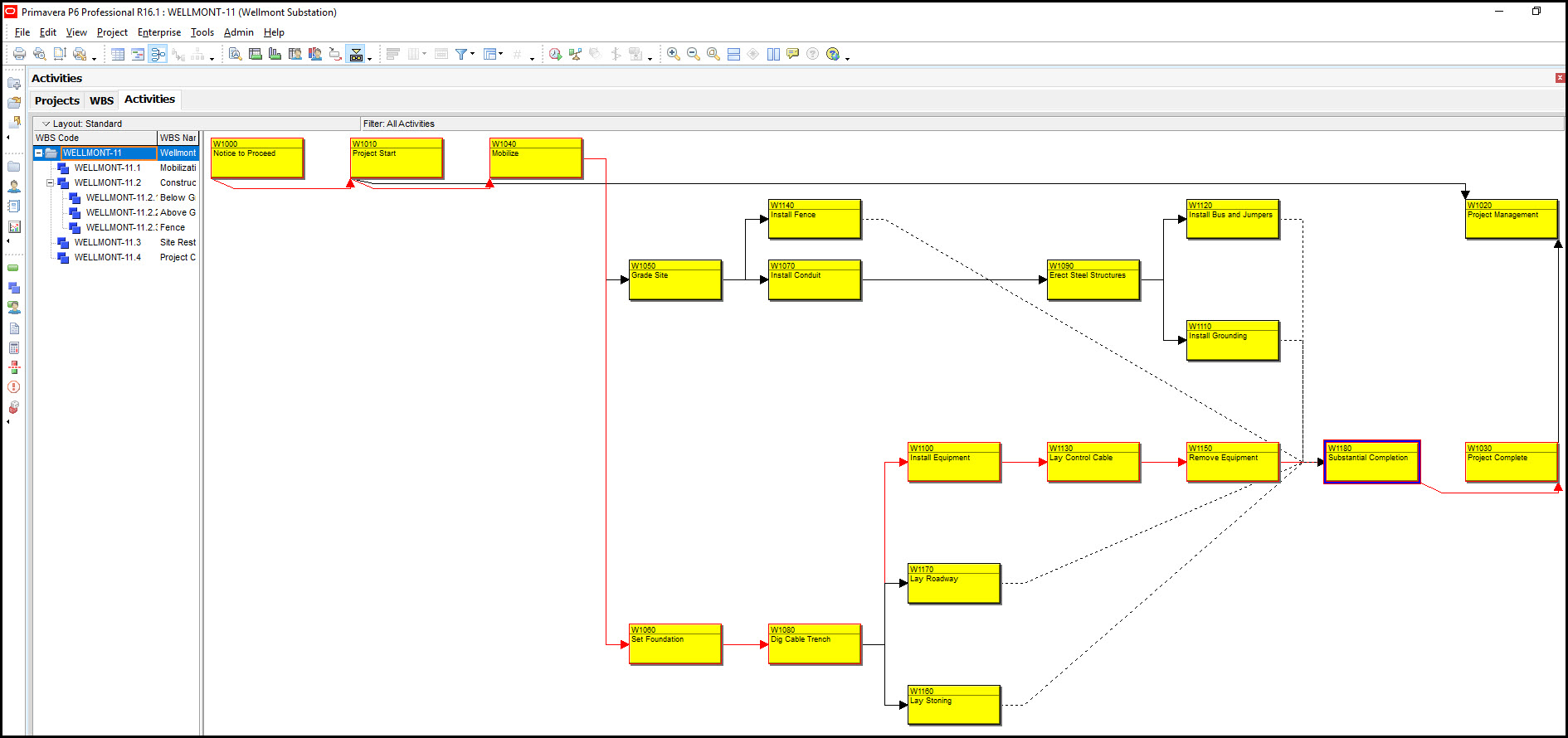
A Network Diagram is a graphical way to view tasks, dependencies, and the critical path of your project. Boxes (or nodes) represent tasks, and dependencies show up as lines that connect those boxes. After you've switched views, you can add a legend, customize how your boxes appear, and print your Network Diagram.. To find the Network diagram view, choose View > Network Diagram.
In the Sequence Activities process of Project Time Management, the major output is a Network Diagram.But what is a Network Diagram? In the online PMP training, its purpose is explained as "visualizing the project activities in boxes with the activity IDs and showing the interrelationship of activities with arrows".Network diagrams tell if an activity will start before, after or at the same ...
Schedule Development. Network Diagrams are a graphical portrayal of the activities and events of a project. They show how each activity relates to others in the project, the sequence of activities, and the need to perform some tasks before others. Networks also facilitate the determination of the impact of early or late starts or finishes ...
The network planning is the categorisation of the activities involved in project implementation in a sequential order followed by a schematic presentation of the activities necessary for the entire project. The steps are to: A. Identify and list the category of activities involved from the start to the completion of the project.
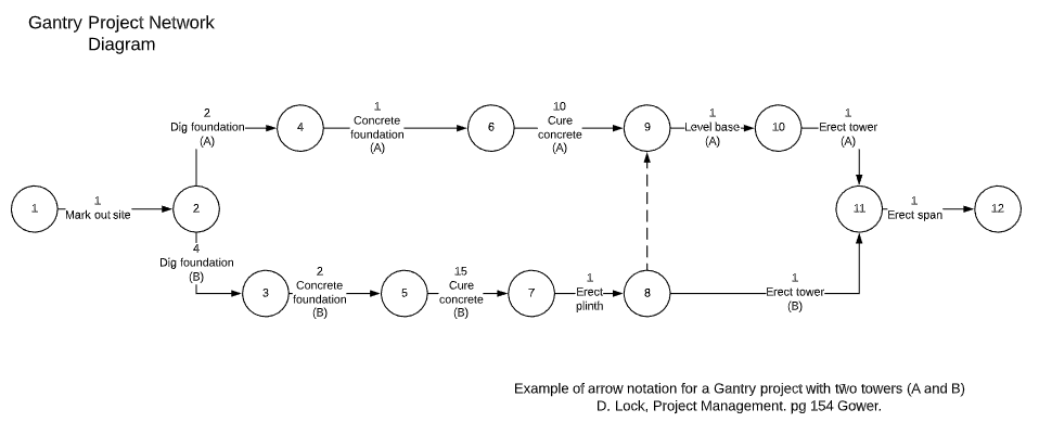
Project schedule network diagrams can be divided into two types, the arrow diagram method (ADM) and the precedence diagram method (PDM). As expected, the arrow diagram method or activity on arrow network diagram uses arrows to represent the project activities, with the tail of the arrow being its start and the point the finish.
project schedule network diagram. is a graphic representation of dependencies recognized during the planning phase. Finish-to-start. most common relationship between tasks. lead time. successor task starts before its predecessor ends. lag time. makes the successor task start some time after its predecessor ends.
Project Schedule Network Diagram: This is a broad term used to encompass elements of the project from the planning stages through the completion of the project. Chronology is important so this diagram is always completed in a left to right manner. Network Logic: This is a collection of the logic that is related to building the various diagrams ...
The project schedule network diagram typically refers to a particular input/output mechanism that represents a particular schematic display of any and all lo...

Project Schedule Network Diagram High Task Variety Difficult Measure Powerpoint Presentation Images Templates Ppt Slide Templates For Presentation
Creating A Network Diagram in Excel and Word. A network diagram is a project management flow chart that displays the relationships between all the components of a project. The illustrative format makes it easy to determine the flow of the project, where you currently are in the project's life-cycle and links between parallel and successive activities as well, all with just a quick glance.
PDM is a scheduling technique of the 'sequence activities' process in PMI methodology. The precedence diagramming method can be used for creating a project schedule network diagram which is an output of this process that is used as an input for the 'develop schedule' process (PMBOK, ch. 6.3.2, 6.5).
What does "Network Diagram" functionality do? The Network Diagram functionality allows a visual representation of the project plan. It represents tasks and task dependencies. A box (also called a node) represents each task, and a line connecting two boxes represents the dependency between two tasks.
A diagram displaying dependencies and logic between project activities, best used during the planning stages of a project. See also bar chart, milestone chart. Project Schedule Network Diagram Example. Created in: Sequence Activities (P) Input to: Develop Schedule (P) Part of: Project documents.
A network diagram will help us focus in on the activity relationships. To display a network diagram of the schedule select the Task tab, View ribbon group, Gantt chart drop down menu, and Network Diagram, Figure 2. Figure 2. The network diagram for our demonstration project is displayed in Figure 3. Figure 3.
The project schedule network diagram typically refers to a particular input/output mechanism that represents a particular schematic display of any and all logical relationships that may exist between the existing project schedule activities. The project schedule network diagram when properly laid out is always laid in a left to right display to ...

Project Schedule Network Diagram Explained With Examples Knowledge Hub For Project Management Professionals
A project schedule network diagram is created by (an output of) the PMI process to sequence activities. The diagram is then used in the process, develop schedule. Basically the project schedule network diagram is a way to visually portray the sequences of the activities in the project. When combined with other factors, such as activity duration estimates and resource calendars, a project ...
The project schedule network diagram captures the order in which the project activities should be scheduled to address their logical relationships. It has different intersections, generally known as nodes, that symbolize the activities, whereas the arrows show the sequence and interdependencies of these activities.
An effective project schedule network diagram will serve as a clear and concise representation of the project. The Arrow diagram and the Precedence diagram are the two types of network diagrams that exist. In an Arrow diagram, nodes are used to depict events and arrows are used for activities, ...















0 Response to "43 project schedule network diagram"
Post a Comment