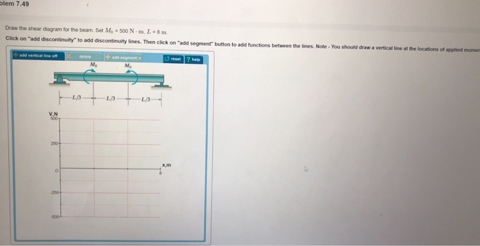
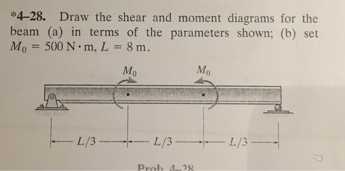
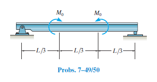
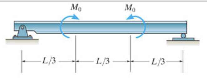
44 draw the shear diagram for the beam. set m0 = 500 n⋅m, l = 8 m.
0.1 m 300 N 0.2 m Q B 45° D 0.2 m 0.2 m 0.28284 m SOLutiOn (a) F F x y = ∞ = = ∞ = = ( )cos. ( )sin. ( . 300 25 271 89 300 25 126 785 271 N N N N F 89 126 785 N) ( . )i+ N j r i j M r F M i j = = - - = ¥ = - - ¥ DA D D uuur ( . ) ( . ) [ ( . ) ( . ) ] [(0 1 0 2 0 1 0 2 271 m m m m . ) ( . ) ] ( . ) ( . ) ( . 89 126 785 12 6785 54 378 41 ... Section 1.4 P1.13 Dimensional Analysis The term x has dimensions of L, a has dimensions of LT −2 , and t has dimensions of T. Therefore, the equation x = ka m t n has dimensions of e L = LT −2 j aTf m n or L1 T 0 = Lm T n − 2 m . The powers of L and T must be the same on each side of the equation. Therefore, L1 = Lm and m = 1 .
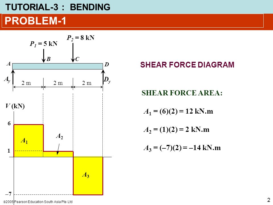
desirable to draw the V-diagram below the FBD of the entire beam, and then draw the M-diagrambelow the V-diagram. The bending moment and shear force diagrams of the beam are composites of the V and M diagrams of the segments. These diagrams are usually discontinuous, or have discontinuous slopes.
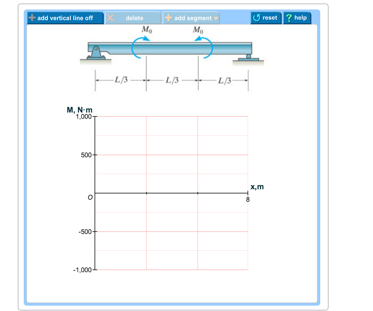
Draw the shear diagram for the beam. set m0 = 500 n⋅m, l = 8 m.
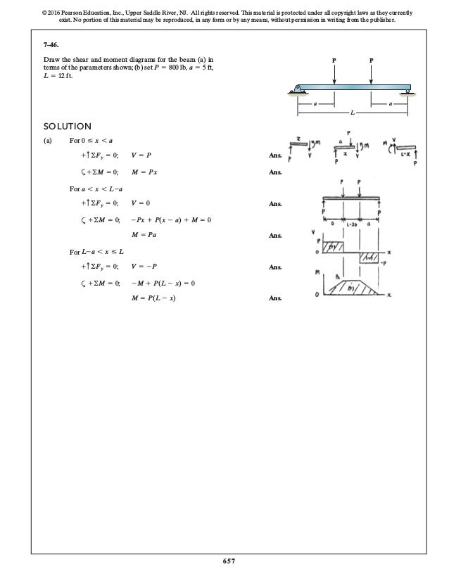
Draw the shear and moment diagrams for the 300 lb 200 lb/ft cantilever beam. HibbelerThank you guys for Gears on steel constructions, beams and suchlike Figure 7. Draw the shear diagram for the beam set m0 500 nm l 8 m. B set m0 500 n m l 8m. d. Draw the shear diagram under the free-body-diagram. 8 x 76. 1-127 16. Problem 7.46 Part A Draw the shear diagram for the beam. Set M0 = 500 N⋅m, L = 8 m. Click on "add discontinuity" to add discontinuity lines. Then click on "add segment" button to add functions between the lines. Question: Problem 7.46 Part A Draw the shear diagram for the beam. Set M0 = 500 N⋅m, L = 8 m. First-Asian-Experienced-Plaxis-User-Course-2003-2
Draw the shear diagram for the beam. set m0 = 500 n⋅m, l = 8 m.. V = 200 N 0 … x 6 3 m 6-35. Draw the shear and moment diagrams for the beam and determine the shear and moment as functions of x. 3 m 3 m x AB 200 N/m 400 N/m Ans: M = e - 100 9 x 3 + 500x - 600f N # m For 3 m 6 x … 6 m: V = e - 100 3 x2 + 500f N, For 0 … x 6 3 m: V = 200 N, M = (200x) N # m, x (m) V (N) 0 200 0 3 3.87 3 3.87 600 691 6 ... L. P. Draw a free body diagram of the beam, isolated from its environment i.e., show all the forces acting on the beam alone; show all relevant dimensions; show a reference cartesian axes system ... Engineering Vibration. Solution Manual | Daniel J. Inman | download | Z-Library. Download books for free. Find books Biblioteca en línea. Materiales de aprendizaje gratuitos. Ninguna Categoria Subido por Angie Melissa Fluidos- Frank M. White- Fluid Mechanics- Solutions
determining the maximum bending stress in a prismatic beam: •Draw the bending moment diagram by one of the methods described in Chapter 4. Identify the bending moment M ... I m M N m y m N m ⋅ σ = Sample Problem 5.1 The simply supported beam in Fig. (a) has a rectangular cross ... The shear force and bending moment diagrams. M max = +16 kN ... A simply supported beam carries a uniformly distributed load of q. Find the resulting vibration of the beam when the load is suddenly removed. Solution. w = ∑ sin nπx L A n cos ω n t + B n sin ω n t. where. ω n = n 2 π 2 EI m L 4. at t = 0. w t = 0 = ∑ A n sin nπx L w ˙ t = 0 = ω n ∑ B n sin nπx L. The beam will fail when the maximum shear force is Vmax or the maximum bending moment is Mmax. Determine the magnitude M0 of the largest couple moments it will support. Units Used: kN = 103 N. Given: L = 9 m. Vmax = 5kN. Mmax = 2kN ∙ m 1. Draw the shear diagram for the beam. Set M0 = 500 N?m, L = 8 m. 2. Draw the moment diagram for the beam. Thanks for the help! Question: 1. Draw the shear diagram for the beam. Set M0 = 500 N?m, L = 8 m. 2. Draw the moment diagram for the beam. Thanks for the help!
Solution for 6-74* The rectangular plate of uniform thickness shown has a mass of 500 kg. Determine the tensions in Fig. in the three cables supporting the… Solution for Draw the shear diagram for the beam. Set Mo = 500 N⋅m, L = 8 m. Draw the moment diagram for the beam. Set Mo = 500 N⋅m, L = 8 m. Draw the shear and moment diagrams for the beam, and determine the shear and moment throughout the beam as functions of x. 2 kip/ft 8 kip x 10 kip 40 kip ft A 30 kip ft B 5 ft 5 ft 2 kip/ft 5 ft 6-19. Draw the shear and moment diagrams for the beam. 06 Solutions 46060_Part1 5/27/10 3:51 PM Page 338 Find the total 20 M U L T I V E R S E E S T Y P 2 A M 22 N 21 M I L L I B A R I G P N E U M A T I C S L work performed by the gas (in joule) , if it is given N 23 E R S C R E W that volume at B is 100 m3 and at C it is 1600 m3.
Problem 1 Using Graphical Method Draw The Shear And Bending Moment Diagrams For The Beam Shown In The Figure Determine The Absolute Maximum Bending Ppt Video Online Download
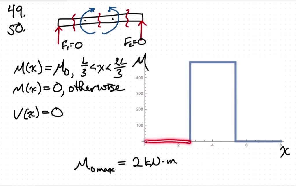
L 3 Draw the shear and moment diagrams for the beam (a) in terms of the parameters shown; (b) set L = 8 m. M0 = 500 N # m, L/3 L/3 L/3 M0 M0 Ans: 0 … x 6 L 3 : V = 0, M = 0 L 3 6 x 6 2L 3 : V = 0, M = M0 2L 3 6 x … L: V = 0, M = 0 0 … x 6 8 3 m: V = 0, M = 0 8 3 m 6 x 6 16 3 m: V = 0, M = 500 N # m 16 3 m 6 x … 8 m: V = 0, M = 0 53.
Sathyabama Ac In
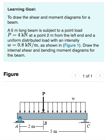
Example 1-2 A simple beam with an overhang is supported at points A and B (Fig. 1-10). A linearly varying distributed load of peak intensity q0 5 160 N/m acts on span AB. Concentrated moment M 0 5 380 N ⋅ m is applied at A, and an inclined concentrated load P 5 200 N acts at C.
2 Static Equilibrium Force And Moment Get A Free Blog Here
Magnitude: l = r⋅ psin ϕ= r⋅m⋅vsin ϕ= r⋅m⋅v⊥ = r⋅ p⊥ = (rsin ϕ)p = r⊥ p = r⊥m⋅v l positive counterclockwise l negative clockwise Direction of l is always perpendicular to plane formed by r and p. Units: kg m 2/s. III. Newton's second law in angular form dt dp
Lpuguidecom Files Wordpress Com
A student using this manual is using it without permission. f PROBLEM 5.2 For the beam and loading shown, (a) draw the shear and bending-moment diagrams, (b) determine the equations of the shear and bending-moment curves. SOLUTION Reactions: L wL ΣM B = 0: − AL + wL ⋅ =0 A= 2 2 L wL ΣM A = 0: BL − wL ⋅ =0 B= 2 2 Free body diagram for ...

Determine The Normal Shear Force And Bending Moment At C And D Youtube
L Jose Rangel. Download Download PDF. Full PDF Package Download Full PDF Package. This Paper. A short summary of this paper. 1 Full PDF related to this paper. Read Paper. PROBLEM 6.1.
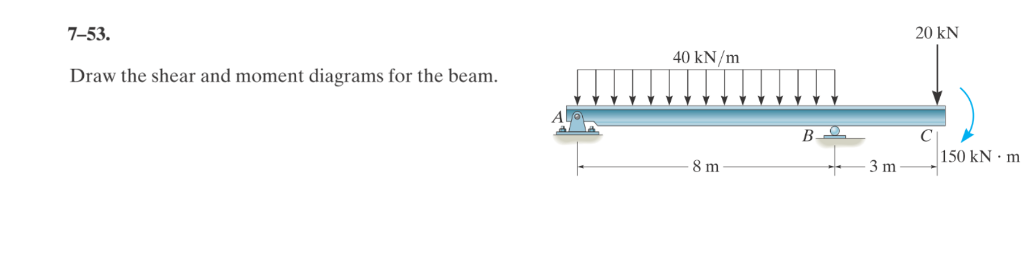
Solved 7 53 20 Kn 40 Kn M Draw The Shear And Moment Chegg Com
Nuclear Energy Fission And Fusion Concept Diagram Nuclear Energy Nuclear Physics Nuclear Engineering Diagram illustrating in a schematic way the technical difficulties of nuclear fusion which much bring positively charged nuclei close enough so that the nuclear force will kick […] In nuclear physics, nuclear fusion is a nuclear reaction in which two or more atomic nuclei come very close and ...

Mcgraw Hill Education All Rights Reserved No Reproduction Or Distribution Without The Prior Written Consent Of Mcgraw Hill Education Pdf Geometry Space
Normal and shear stresses in beams, shafts, and rods can be calculated from the basic formulas of mechanics of materials. For instance, the stresses in a beam are given by the flexure and shear formulas ( σ ( z ) = M y z I y and τ ( z ) = Qz S *y b ( z ) I y ), and the stresses in a shaft are given by the torsion formula (τ

Problem 1 Using Graphical Method Draw The Shear And Bending Moment Diagrams For The Beam Shown In The Figure Determine The Absolute Maximum Bending Ppt Video Online Download
Given: L = 2 m, E = 200 × 109 N/m2 , I = 1.15 × 10⁻⁴ m4 , m = 20 kg Find: keq Solution: The deflection of a pinned-pinned beam at its midspan is determined using Table D.2 with a = L/2, Z = L/2 as EI48 L 2LZy 3 == )/( The equivalent stiffness is the reciprocal of the deflection, m N 101.38 (2m) )m10)(1.15 m N 1048(20 48 8 3 44 2 9 3 ×= ×× ...
Lpuguidecom Files Wordpress Com
(figure 1) draw the shear diagram for the beam. set m0 = 500 n⋅m l = 8 m draw the shear diagram for the beam. set p = 600 lb a = 5 ft b = 7 ft draw the shear diagram for the beam. set p = 800 lb a = 5 ft l = 12 ft draw the shear diagram for the compound beam which is pin connected at b
Anvari Net
shear, so too we will use the same moment/curvature relationship to produce a dif-ferential equation for the transverse displacement, v(x) of the beam at every point along the neutral axis when the bending moment varies along the beam. Mb EI -d s dφ = The moment/curvature relation-ship itself is this differential equa-tion.
Solved Draw The Shear And Moment Diagrams Of The Beam A In Terms Of The Parameters Shown B Set M 0 500 Mathrm N Cdot Mathrm M L 8 Mathrm M
First-Asian-Experienced-Plaxis-User-Course-2003-2
Sathyabama Ac In
Problem 7.46 Part A Draw the shear diagram for the beam. Set M0 = 500 N⋅m, L = 8 m. Click on "add discontinuity" to add discontinuity lines. Then click on "add segment" button to add functions between the lines. Question: Problem 7.46 Part A Draw the shear diagram for the beam. Set M0 = 500 N⋅m, L = 8 m.
Lpuguidecom Files Wordpress Com
Draw the shear and moment diagrams for the 300 lb 200 lb/ft cantilever beam. HibbelerThank you guys for Gears on steel constructions, beams and suchlike Figure 7. Draw the shear diagram for the beam set m0 500 nm l 8 m. B set m0 500 n m l 8m. d. Draw the shear diagram under the free-body-diagram. 8 x 76. 1-127 16.
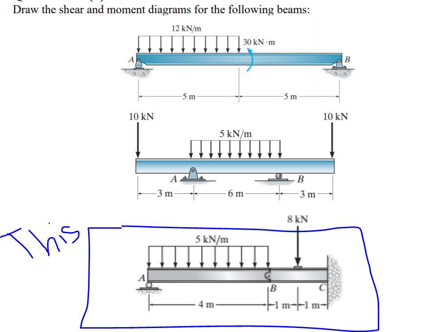
Solved Draw The Shear And Moment Diagrams For The Following Chegg Com
Solved 1 Draw The Shear Diagram For The Beam Set M0 500 Chegg Com
Anvari Net
Eng Auburn Edu

Mechanics Of Materials Pages 201 250 Flip Pdf Download Fliphtml5
Draw The Shear Diagram For The Beam Set M0 500 Nm L 8 M Wiring Site Resource
Chapter 7
Faculty Kfupm Edu Sa
Solved Draw The Shear And Moment Diagrams For The Shaft A In Terms Of The Parameters Shown B Set P 9 Mathrm Kn A 2 Mathrm M L 6 Mathrm M There Is A Thrust Bearing At A
Solved Learning Goal To Draw The Shear And Moment Diagrams Chegg Com

Draw The Shear And Moment Diagrams For The Beam A In Terms Of The Parameters Shown B Set Mo 500 N M L 8 M Study Com
Shear And Moment Diagrams Strength Of Materials Review At Mathalino
Lpuguidecom Files Wordpress Com
Faculty Kfupm Edu Sa
Solved Draw The Shear And Moment Diagrams Of The Beam A In Terms Of The Parameters Shown B Set M 0 500 Mathrm N Cdot Mathrm M L 8 Mathrm M
Solved Blem 7 49 Draw The Shear Diagram For The Beam Set Chegg Com

Mechanics Of Materials Pages 201 250 Flip Pdf Download Fliphtml5
Solution To Problem 405 Shear And Moment Diagrams Strength Of Materials Review At Mathalino
Beermom Ge C09 P001 P
Web Ncyu Edu Tw
Arce 302 Structural Analysis

Solved Problems 6 4 Bending Mechanics Of Materials By R C Hibbeler Draw Shear And Moment Diagram For The Cantilever Beam Civil Engineering Soft Studies

Pdf Engineering Mechanics Statics Problem 1 1 Feels Like Heaven Academia Edu

Pdf Problem 2 1 Adian Sixx Academia Edu

Steel Construction 01 2016 Free Sample Copy By Ernst Sohn Issuu
Solved Draw The Shear And Moment Diagrams For The Beam A Chegg Com
Answered M Mo L B L 3 L 3 L 3 Probs Bartleby

1 A Sketch The Shear Force And Bending Moment Diagr Itprospt
Web Ncyu Edu Tw
Draw The Shear Diagram For The Beam Set M0 500 Nm L 8 M Wiring Site Resource
Answered Draw The Shear Diagram For The Beam Bartleby
0 Response to "44 draw the shear diagram for the beam. set m0 = 500 n⋅m, l = 8 m."
Post a Comment