41 time delay relay wiring diagram
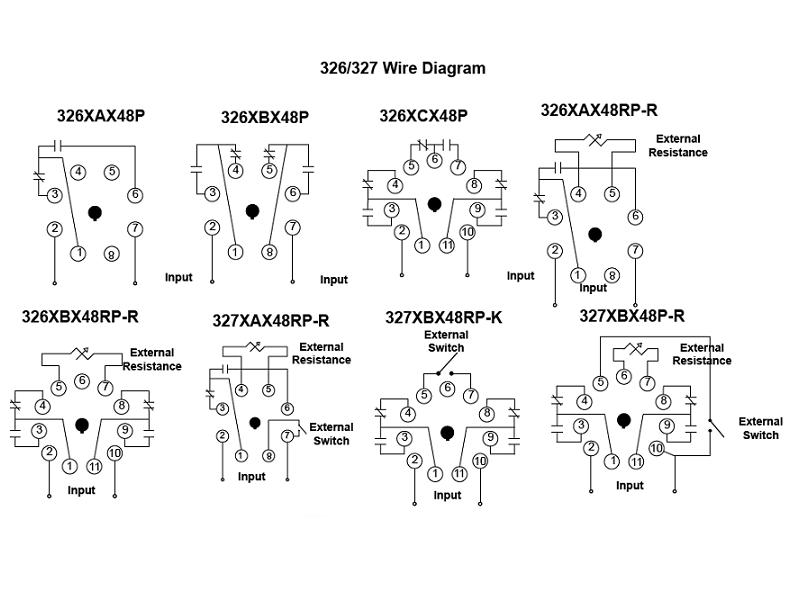
Harmony modular timing relay on and off delay re22r2cmr schneider electric asymmetrical timer for star delta starter 7 spdt zelio re timers Re17rcmu Harmony Modular Timing Relay 8 A 1 Co S 100 H Off Delay 24 V Dc 240 Ac Schneider Electric Global Re22r2acmr On And Off Delay Timing Relay 0 05s 300h 24 240v Ac… Read More » 326 327 Series Time Delay Relays On Struthers Dunn. Relays Electrical Equipment Supplies Westernfertility Com Ac 110v Power On Delay Timer Time Relay 0 10second 10s Ah3 3 8 Pins. Digital Timer Relay 8 Pin 24v Dc 110 240v Ac Ato Com. I Am Trying To Wire A Dayton 1egc6 11 Pin Time Delay Relay Have Cord For Switch And Wired The Power.
55 - Power Factor Relay 56 - Field Application Relay 59 - Overvoltage Relay 60 - Voltage or Current Balance Relay 62 - Time-Delay Stopping or Opening Relay 63 - Pressure Switch 64 - Ground Detector Relay 65 - Governor 66 - Notching or jogging device 67 - AC Directional Overcurrent Relay 68 - Blocking or "out of step" Relay
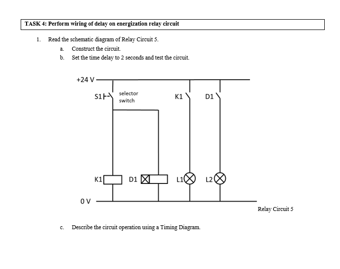
Time delay relay wiring diagram
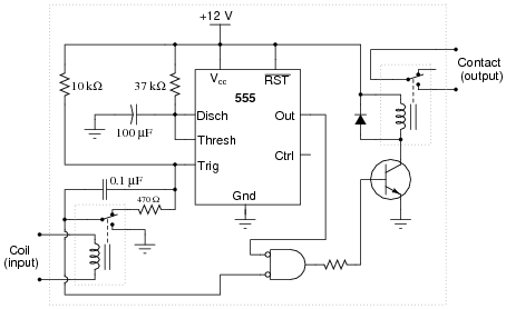
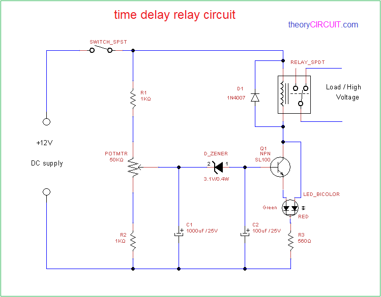
Question 2. A special class of electromechanical relays called time-delay relays provide delayed action, either upon power-up or power-down, and are commonly denoted in ladder logic diagrams by "TD" or "TR" designations near the coil symbols and arrows on the contact symbols. On Delay Relay Contacts Wiring . Ⅴ Time Relay Applications. ... For DC products, pay attention to wiring according to the circuit diagram and pay attention to the polarity of the power supply. 5) After the time relay is out of working state, it should be reset immediately for the next use. If the repeated use interval is less than the preset ... Time Delay Relay can provide a short delay after power is turned on and before switching on the device. The working is very simple and is explained below. The circuit is based on the RC time delay and Zener controlled switch. When the power to the circuit is turned on, the 1000µF capacitor charges through the 100KΩ variable resistor.
Time delay relay wiring diagram. 2.3 Connecting 10amp negative (sink) output timer 3. Understanding Timer Delay Relay Function. Understanding all the time delay relay functions available in multifunctional timer can be an intimidating task. During the circuit design with the timer relay and variety of timer configuration, questions such what Get the FULL video transcript here: https://www.rspsupply.com/education/a-28-time-delay-relays/Want to see similar products to those featured in this video: ... Time Delay Relay · STEP 1 - Installation and Wiring · STEP 2 - Choose your Function · STEP 3 - Choose your Time Range · STEP 4 - Set Time. 8 Pin Relay Wire Diagram Wiring Schematic | Wiring Diagram - 8 Pin Relay Wiring Diagram. You'll be able to usually depend on Wiring Diagram as an essential reference that can help you save time and cash. With all the help of this e-book, you'll be able to easily do your own wiring tasks.
Encapsulated Time Delay Relays December 2020, Rev D 901-0000-295 DANGER! ... Trigger to initiate the unit as indicated by the dotted line in the wiring diagrams above. For Triggered DC Input Voltages, make sure the polarity matches the connection diagram. 12v Timer Relay Wiring Diagram - wiring diagram is a simplified pleasing pictorial representation of an electrical circuit. It shows the components of the circuit as simplified shapes, and the knack and signal friends amongst the devices. A wiring diagram usually gives assistance virtually the relative outlook and arrangement of devices and ... To help understand, some definitions are important: Input Voltage : Control voltage applied to the input terminals (see wiring diagrams below). Depending on the ...7 pages Time delay relays are simply control relays with a time delay built in. Their purpose is to control an event based on time. ... They are represented by the dotted lines in the wiring diagrams. Note that the user must provide the voltage to power the load being switched by the output contacts of the time delay relay.
Product 800 - 843 — Allows control of loads for AC or DC voltages. TRU SERIES. Knob Adjustable Universal Time Delay Relay. Wiring Diagram. Ordering Information.177 pages pcbfm131-time-delay-relay-wiring-diagram 2/3 Downloaded from ahecdata.utah.edu on November 2, 2021 by guest The Road Home-David W. Brown 2010-03 This story takes place in today's world where an alien spaceship is pursued by another alien race and a battle ensues. The fleeing ship winds up in our sector of the universe How To Build Time Delay Relay Circuit · A Relay is an electromechanical device that acts as a switch between two terminals. The switching operation is achieved ... Hella Time Delay Relay Wiring Diagram from static-cdn.imageservice.cloud. Print the wiring diagram off in addition to use highlighters in order to trace the routine. When you employ your finger or even follow the circuit with your eyes, it is easy to mistrace the circuit. One trick that I use is to print out exactly the same wiring plan off twice.
How to Wire A Time Delay Relay Diagrams- wiring diagram is a simplified enjoyable pictorial representation of an electrical circuit.It shows the components of the circuit as simplified shapes, and the gift and signal contacts along with the devices.

Off Delay Timer Wiring Diagram. Solid state timer relay wiring diagram for off delay on time using 555 ic oven full and in a plc circuit the working principle eapl a1da signal motor control timing relays. Eapl A1da Signal Off Delay Timer Electronic Automation Private Limited Id 19752040155.
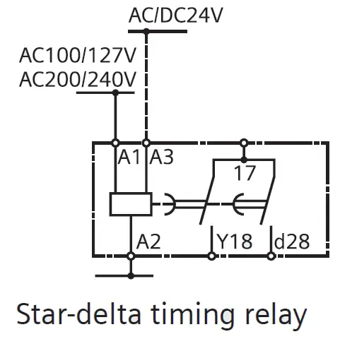
(except for GT3F "true power OFF Delay"). 2. NO = Normally open. 3. NC = Normally closed. Timing Function Diagrams Overview ON-Delay 1 (power start) When voltage is applied to the coil, the relay contacts remain in the off state and the set time begins. When the set time has elapsed, the relay contacts transfer to the on state. The contacts ...

Time delay relays are simply control relays with a time delay built in. Their purpose is to control an event based on time. The difference between relays and time delay relays is when the output contacts open & close: on a control relay, it happens when voltage is applied and removed from the coil; on time delay relays, the contacts can open or ...

Size: 34.73 KB. Dimension: 667 x 333. DOWNLOAD. Wiring Diagram Pics Detail: Name: dayton time delay relay wiring diagram - foxy wiring diagram for time delay relay the symbol daytontimer full size with motor symbol circuit. File Type: JPG. Source: gvsigmini.org. Size: 57.90 KB. Dimension: 1280 x 1024.

... in the wiring diagrams. Note that the user must provide the voltage to power the load being switched by the output contacts of the time delay relay.6 pages

Time Delay Relay Wiring Diagram Download. time delay relay wiring diagram - Just What's Wiring Diagram? A wiring diagram is a sort of schematic which utilizes abstract pictorial signs to show all the interconnections of elements in a system. Wiring layouts are made up of 2 things: signs that stand for the components in the circuit,…

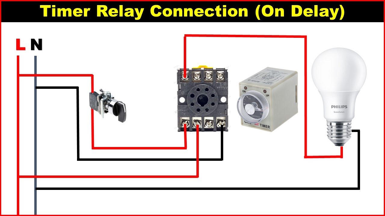
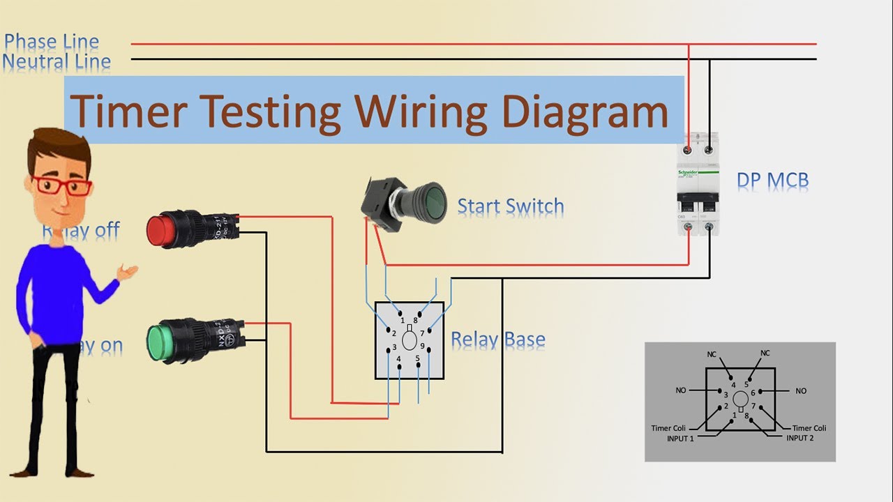
on delay timer wiring diagram | 8 pin timer relay wiring diagram Assalam-o-AlaikumHiFriendsI am Muhammad Bilal Welcome to our youtube channel Mian Electric ....

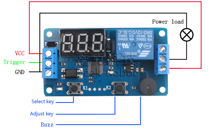
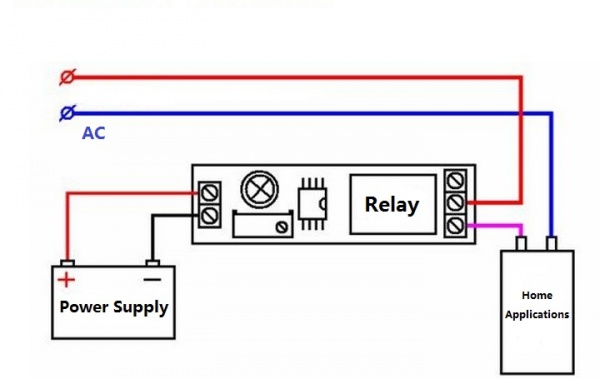
The relay has normally open and normally close contact. To control a load (a lamp or a pump), we should connect the wire to normally open contact. Please look at this picture: Make sure to remove s5 jumper. I suggest you try with low voltage first, for example, using the same battery (9v) to control a DC lamp or a LED with 560 Ohm resistor in ...

Non-programmable Plug-In Time Delay Relays Wiring Wire the socket per the wiring diagram on the side of the time delay relay. Note: For products that use a Control Switch to initiate the unit, this Control Switch is a dry-type contact (applying voltage to the pins could damage the unit). For products using a Power Trigger to initiate the

Delay On Break Timer Wiring Diagram Gallery. Variety of delay on break timer wiring diagram. A wiring diagram is a simplified traditional pictorial depiction of an electric circuit. It reveals the parts of the circuit as streamlined shapes, and the power as well as signal links between the devices. A wiring diagram generally provides details about the…

Off Delay Timer Relay Wiring Diagram. Amarante Pruvost. August 20, 2021. Find Instant Quality Info Now. Get Results from multiple Engines. This Post Is About The Staircase Timer Wiring Diagram In The Diagram I Use The On Delay Timer Finder 8 Pin Relay Re Electrical Circuit Diagram Timer Diagram.
Time Delay Relays. DELAY-ON-BREAK. Wiring Diagram. L1. N/L2. L1. N/L2. 8-PIN OCTAL SPDT. S1 = Initiate Switch. Relay contacts are isolated. 11-PIN DPDT.

P3: Relay will turn ON for time OP after getting a trigger signal and then turn relay OFF.Module will reset and stop timing if it gets a trigger signal again during delay time OP. P4: Relay will turn OFF for time CL after getting a trigger sighal and then relay will turn ON for time OP.Relay will turn OFF after finish timing.
Time Delay Relay Wiring Diagram Download July 30, 2018 July 16, 2018 by faceitsalon Assortment of time delay relay wiring diagram it is possible to download for free.
Rly02807 American Standard Trane Air Handler Fan Time Delay Relay - Air Handler Fan Relay Wiring Diagram. Wiring Diagram includes the two illustrations and step-by-step instructions that might allow you to definitely actually construct your undertaking. This is beneficial for both the folks and for specialists that are seeking to find out ...

8 Pin Relay Wiring Diagram - 8 pin ac relay wiring diagram, 8 pin flasher relay wiring diagram, 8 pin octal relay wiring diagram, Every electrical structure is made up of various different components. Each component should be set and linked to other parts in specific way. Otherwise, the arrangement will not function as it should be.

Time Delay Relay can provide a short delay after power is turned on and before switching on the device. The working is very simple and is explained below. The circuit is based on the RC time delay and Zener controlled switch. When the power to the circuit is turned on, the 1000µF capacitor charges through the 100KΩ variable resistor.

On Delay Relay Contacts Wiring . Ⅴ Time Relay Applications. ... For DC products, pay attention to wiring according to the circuit diagram and pay attention to the polarity of the power supply. 5) After the time relay is out of working state, it should be reset immediately for the next use. If the repeated use interval is less than the preset ...

Question 2. A special class of electromechanical relays called time-delay relays provide delayed action, either upon power-up or power-down, and are commonly denoted in ladder logic diagrams by "TD" or "TR" designations near the coil symbols and arrows on the contact symbols.


0 Response to "41 time delay relay wiring diagram"
Post a Comment