43 draw the shear diagram for the compound beam which is pin connected at b.
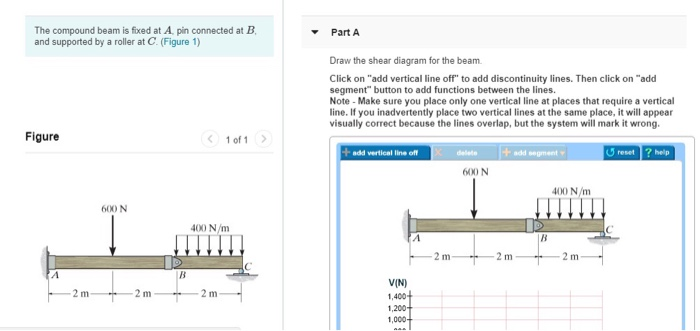
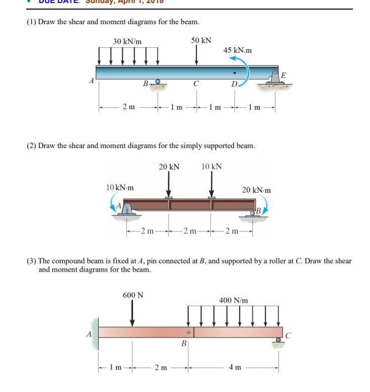
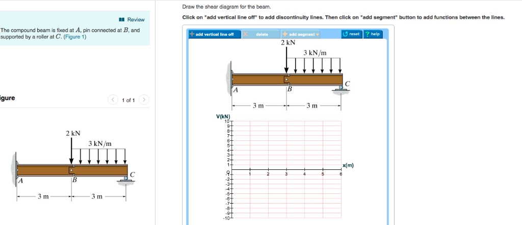
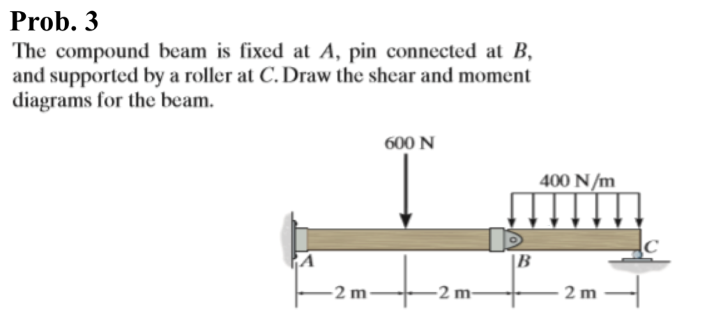
The compound beam is fixed at A, pin connected at B, and supported by a roller at C. Draw the shear and moment diagrams for the beam. Results. See All Results. Question: Mechanics of Materials - Instructor Solutions Manual [EXP-4667] Shear and moment diagrams and formulas are excerpted from the Western Woods Use Book, 4th edition, and are provided herein as a courtesy of Western Wood Products Association. Introduction Notations Relative to "Shear and Moment Diagrams" E = modulus of elasticity, psi I = moment of inertia, in.4 L = span length of the bending member, ft.
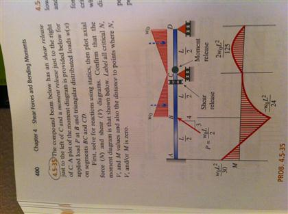
A compound beam is subjected to three concentrated loads, as shown in Figure 9.16a. Using influence lines, determine the magnitudes of the shear and the moment at A and the support reaction at D. Fig. 9.16. Compound beam. Solution. First, draw the influence line for the shear force V A, bending moment M A, and reaction C y.
Draw the shear diagram for the compound beam which is pin connected at b.
Port B of motor will be connected to exhaust R and air in motor will be exhausted through port R via DC valve. ... Draw p-v and T-S diagram for Diesel cycle. Name the processes involved in it. ... A sliding block attached to the crank pin at B slides along the slotted bar AP and thus causes AP to oscillate about the pivoted point A. Welcome to the Multi-span Beam Calculator. Draw the shear and moment diagrams for the simply supported beam. b- Write Jan 12, 2018 · Draw the shear diagram for the compound beam which is pin connected at b. 7-78: Draw the shear and moment diagrams for the beam. Question: *11-8. Students may use the Materials Science section of 7. · 7-69. Drawing shear force and bending moment diagram for a compound beam#Engineering #civil_engineering #structuralengineering #structural_engineering#هندسة_مدنية#...
Draw the shear diagram for the compound beam which is pin connected at b.. the compound beam in the attachnent is fixed at A, pin connected at B, and supported by a roller at C. part A. draw the shear diagram for the beam. part B. draw the moment for the beam. fullscreen Expand. Pin-Connected Frame. For rigid plane frames, there are three requirements for complete analysis: (1) finding the values of the reaction components, (2) modelling how the principal stresses (axial, shear, and moment) act on the structure, and (3) determining the deflected shape. An interesting feature of this problem is that we have an internal ... (Solution) Draw the influence line diagram for (a) the Moment at C,(b) the Shear just to the right of , and (c) the vertical reaction at B. Solve this problem using the basic method. Assume A is a pin, and B is a roller. [ Prob 6-13. chapter – 6, Structural Analysis by R C Hibbeler] Problem 6-15. F.1 (b), the positive sign convention is (a) tension axial force, (b) shear forces that produce clockwise moments and (c) bending moments that result in tension stresses in the interior frame fibers. The sign convention of F.1(b) can be seen to be equivalent to the beam sign convention rotating columns AB and CD to line up with beam BC.
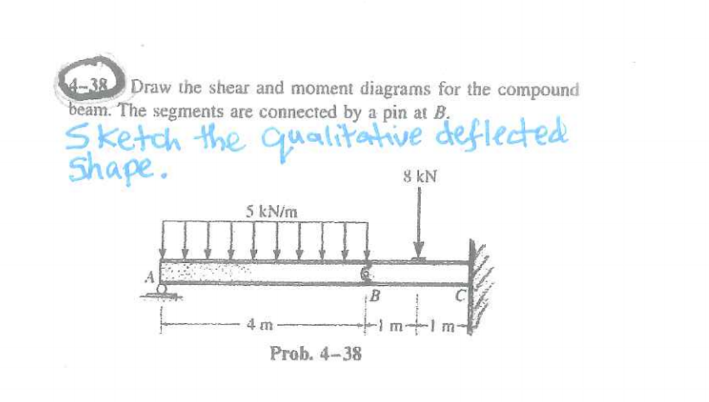
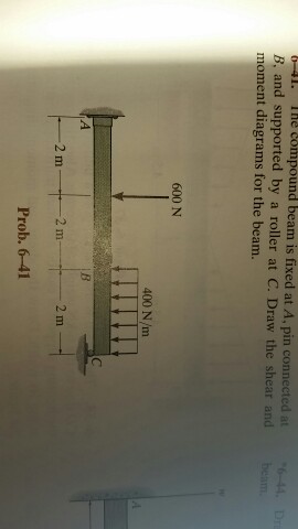
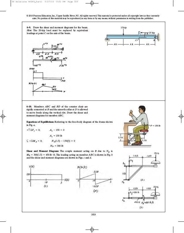
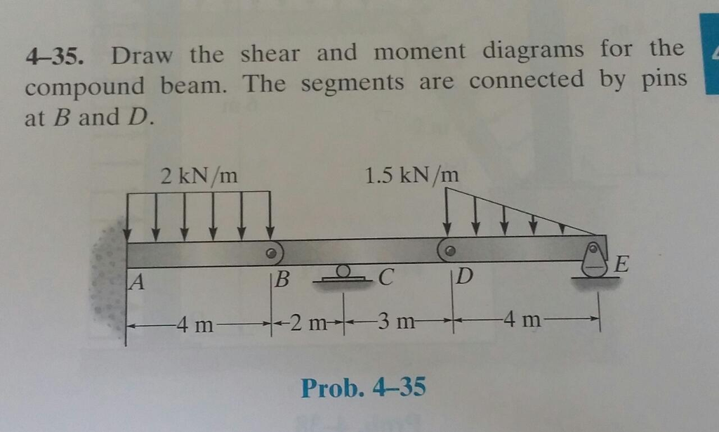
A short link at B is used to connect beams AB and BC to form the compound beam shown. Draw the shear and moment diagrams for the beam if the supports at A and B are considered fixed and pinned, respectively. Problem 25. The simple beam A B shown in the figure supports a concentrated load and a segment of uniform load. (a) Draw the shear-force and bending-moment diagrams for this beam. (b) Find the value of P that will result in zero shear at x = 4.2 m. Draw the shear-force and bending-moment diagrams for this case. Now, flip the beam horizontally 180º (or change the observation point, looking at the beam from the opposite side) and draw the diagrams, starting from the same point A. The diagrams will appear as follows: Note that, while the shear force diagrams appeared to be mirrored images (flipped horizontally), the bending moment diagram is not affected. 6—41. Draw the shear and moment compound beam. The three segments pins at B and E. diagrams for the are connected by 0.8 kN/m o Ans. —4 Shear and Moment Diagram: 6—38. The dead-weight loading along the centerline of the airplane wing is shown. If the wing is fixed to the fuselage at A, determine the reactions at A, and then draw the shear and
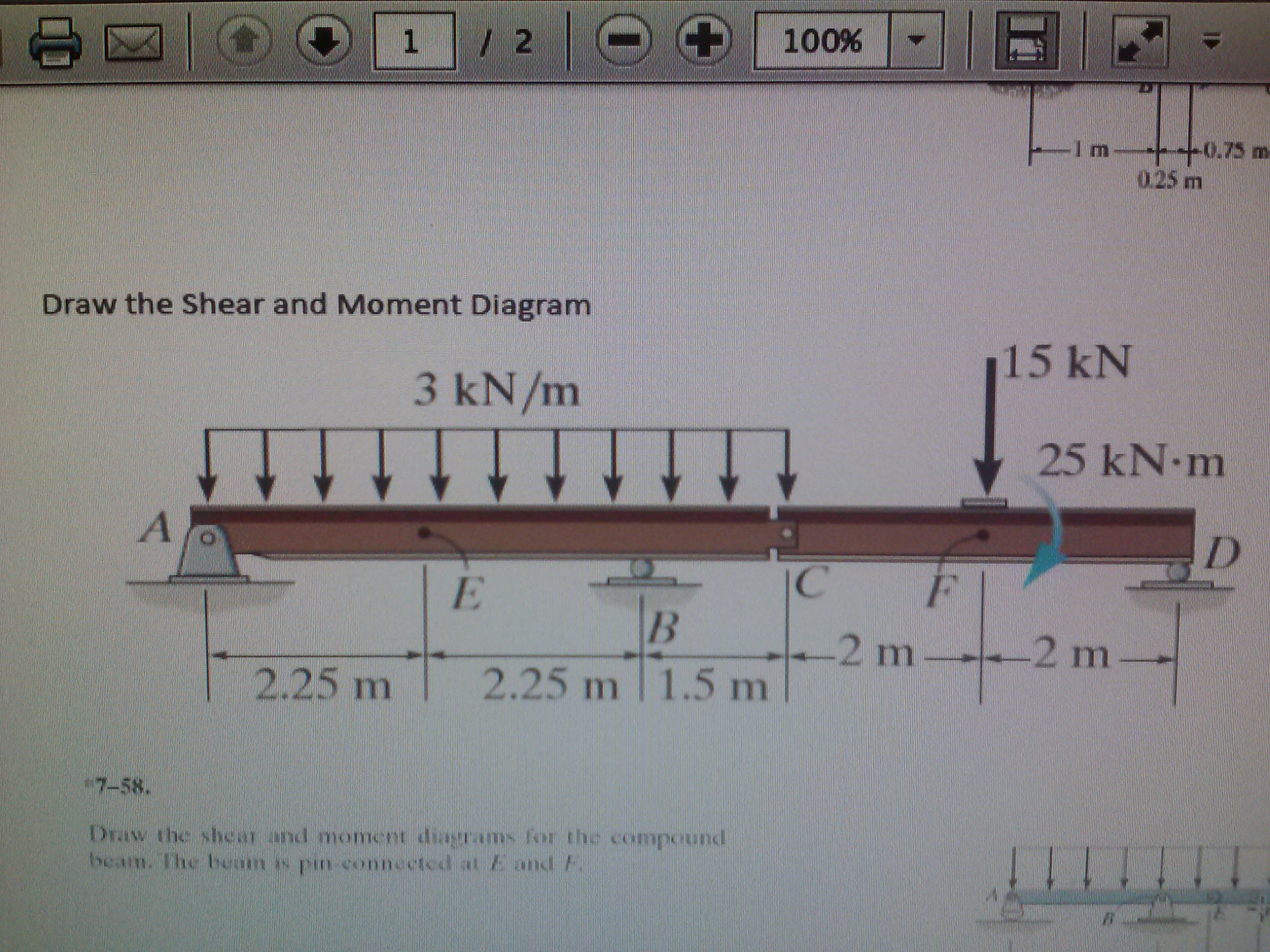
4.3 Shear- Moment Equations and Shear-Moment Diagrams The determination of the internal force system acting at a given section of a beam : draw a free-body diagram that expose these forces and then compute the forces using equilibrium equations. The goal of the beam analysis -determine the shear force V and The compound beam is fixed at A, pin connected at B, and supported by a roller at C. Draw the shear and moment diagrams for the beam. Prob. 6?41 . This problem has been solved! See the answer See the answer See the answer done loading. Show transcribed image text Expert Answer. Take-Home: Problem 6.7, Page 279 Draw the shear and moment diagrams for the compound beam which is pin connected at B . Draw the shear and moment diagrams for the pipe. The end screw is subjected to a horizontal force of 5 kN. Hint: The reactions at the pin C must be replaced by an equivalent loading at point B on the axis of the pipe. Analysis of Simple Diaphragm and Shear Wall Systems Problems ... pin-connected joint fixed support A B P actual beam L/2 L/2 torsional spring joint pin support torsional spring support idealized beam A B ... The compound beam is stable. It is also indeterminate to the second degree.
Solved: The Compound Beam Is Fixed At A. Pin Connected At ...
Step 1. 1 of 7. In this task, we need to draw the shear and moment diagrams for the beam. Also, we need to determine the values of the bending moment at point. B B B. . Step 2. 2 of 7. Free body diagram.

Draw The Shear Diagram For 0 X 14 Ft Of The Compound Beam ...
Beams -SFD and BMD: Example (4) Draw the SFD and BMD for the beam Solution: Draw FBD of the entire beam and calculate support reactions using equilibrium equations Reactions at supports: 2 wL R A R B w Develop the relations between loading, shear force, and bending moment and plot the SFD and BMD ME101 - Division III Kaustubh Dasgupta 10

*7-56, Draw The Shear And Moment Diagrams For The ...
In the other diagram showing track 164, the number in the frame for the same wire/circuit will change to the number 2, as that is the track number for where the wire/circuit came from on this diagram. 3 - Relay Panel - Indicated by grey area. 4 - Diagram of threaded pin on relay panel White circle shows a detachable connection. 5 - Fuse designation Use legend at bottom of …
Solved: The Compound Beam Below Has An Shear Release Just ...
The compound beam is fix supported at A, pin connected at B and supported by a roller at C. Draw the shear and moment diagrams for the beam. 3 ft 610 C B A 6 ft 7 Solutions 44918 1/27/09 10:39 AM Page 611 © 2010 Pearson Education, Inc., Upper Saddle River, NJ.
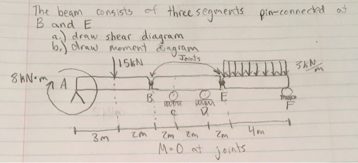
Solved: The Beam Consists Of Three Segments Pin-connected ...
Draw the shear and moment diagrams for the beam. Draw the shear and moment diagrams for the beam.
Solved: The Beam Consists Of Three Segments Pin Connected ...
"Strength of Materials" 4th Edition by "Ferdinand L.Singer" & "Andrew Pytel"
Solved: (1) Draw The Shear And Moment Diagrams For The Bea ...
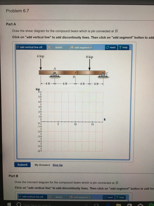
Draw the shear and moment diagrams for the beam. 2 m 3 m 10 kN 8 kN 15 kNиm 6-6. Draw the shear and moment diagrams for the overhang beam. A B C 4 m 2 m 8 kN/m 6-7. Draw the shear and moment diagrams for the compound beam which is pin connected at B. 4 ft 6 kip 8 kip A C B 6 ft 4 ft 4 ft 06 Solutions 46060_Part1 5/27/10 3:51 PM Page 331 5.
Solved: The Beam Consists Of Three Segments Pin Connected ...
Compound beams are structures composed of two or more elements connected by an internal connection. Think of it as two or more beams fastened together. Before proceeding, we highly recommend reading our basics guide in analysing beams as well as how to relate the load, shear, and moment for easy analysis.
Solved: Draw The Shear And Moment Diagrams For The Cantile ...
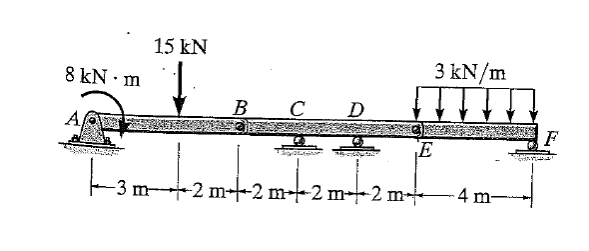
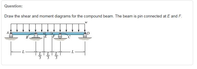
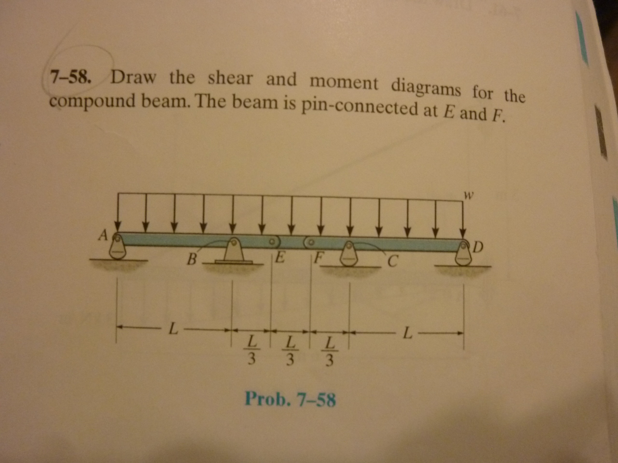
28.5.2018 · Draw the shear and moment diagrams for the compound beam. The beam is pin-connected at E ... The free-body diagram of the beam’s segment sectioned through the arbitrary ... (1.5) - Ay(4.5) = 0 Ay = 6.75 kN 7–81. The beam consists of three segments pin connected at B and E. Draw the shear and moment diagrams for the beam. 4 ...
The Beam Consists Of Three Segments Pin Connected ...
The shear force diagram is shown in Figure 2.25. Illustration – 2.4: The objective is to draw the bending moment and shear force diagram for the beam shown in Figure 2.26. The beam in the example is simply supported at both ends. We will start by computing the reactions at the support. For this, use the equilibrium equation Σ M A = 0:
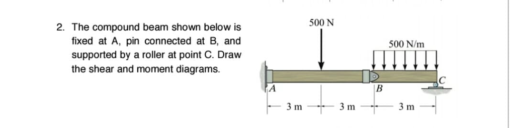
Solved: 500 N 2. The Compound Beam Shown Below Is Fixed At ...
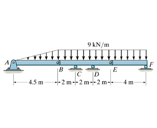
A reinforced concrete pier is used to support the 60 kN 35 kN 35 kN 35 kN 60 kN stringers for a bridge deck. Draw the shear and moment 1 m 1 m 1.5 m 1.5 m 1 m 1 m diagrams for the pier when it is subjected to the stringer loads shown. Assume the columns at A and B exert only vertical reactions on the pier.

Draw The Shear Diagram For The Compound Beam Which Is Pin ...
1. m. 5 kN. Determine the reactions at the supports A and B of the compound beam. 00 kN (T) Ans + c ©F y = 0; F Answer the following questions assuming that the support at A is removed (a) Draw a neat free body diagram of the wheel with the support at A removed (i.
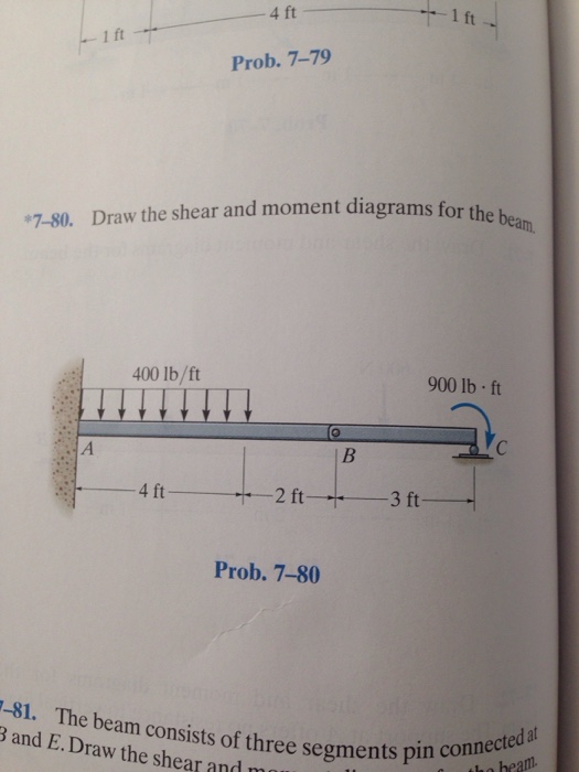
Solved: *7-80 Draw The Shear And Moment Diagrams For The B ...
The compound beam in the attachment is fixed at A, pin connected at B, and supported by a roller at C. (a) Draw the shear diagrams for the beam. (b) Draw the moment for the beam.
Solved: Draw The Shear And Bending Moment Diagram For The ...
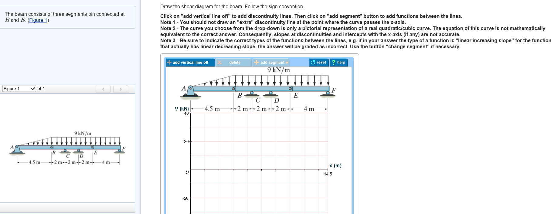
Transcribed image text: Draw the shear diagram for the compound beam which is pin connected at B. Click on "add vertical line" to add discontinuity lines. Then click on "add segment" button to add Draw the moment diagram for the compound beam which is pin connected at B. Click on "add vertical line" to add discontinuity lines.

The compound beam is fixed at A, pin connected at B, and ...
Structural Analysis by R C Hibbeler 8th edition
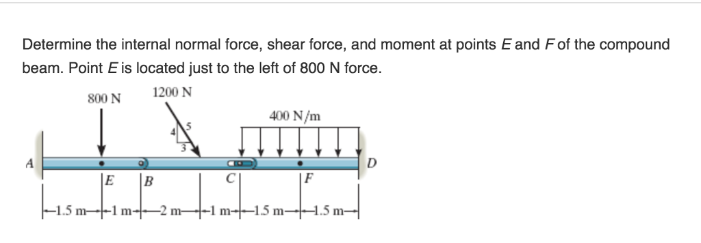
Solved: Determine The Internal Normal Force, Shear Force ...
The compound beam is fixed at A, pin connected at B, and supported by a roller at C. Draw the shear diagram and the moment diagram for the beam.
Solved: Draw The Shear Diagram For The Compound Beam Which ...
The beam shown below is supported by a pin at A and roller at B. Calculate the reactions at both supports due to the loading. 20 kN 40 kN 2 m 3 m 4 m ... Then, draw the shear force diagram (SFD) and bending moment diagram (BMD). b) If P = 20 kN and L = 6 m, draw the SFD and BMD for the beam. P kN L/2 L/2 A B EXAMPLE 4 .

30 Draw The Shear Diagram For The Compound Beam Which Is ...
Problem 6: Bending Moment Diagram Plot shear and bending-moment diagrams for a simply supported beam with a uniformly distributed load; see Figure. Figure Solution A section at a distance x from the left support is taken as shown in figure (b). The shear is found out by subtracting the load to the left of the section from the left upward reaction.
Draw The Shear Diagram For The Compound Beam Which Is Pin ...
2 determine the resultant r on the gusset plate
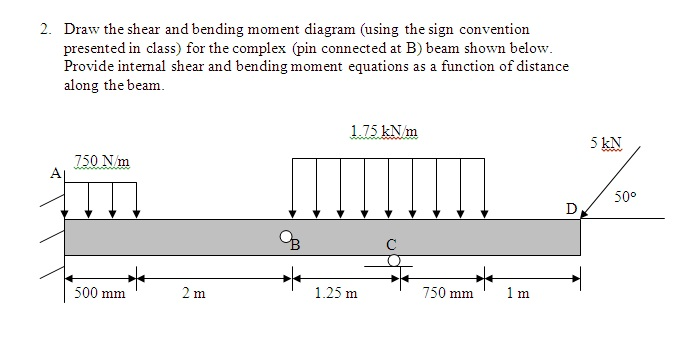
Solved: 2. Draw The Shear And Bending Moment Diagrams For ...
20.11.2021 · Draw the shear diagram for the beam set m0 500 nm l 8 m. 69%. b- Write Jan 12, 2018 · Draw the shear diagram for the compound beam which is pin connected at b. 76. Draw the shear and moment diagrams for the 300 lb 200 lb/ft cantilever beam. 25m c= 1.
Part A: Draw The Shear Diagram For The Compound ...
Due to symmetry, the vertical reactions at B and E are B y = E y = (14.24 kN>m)(5)>2 = 35.6 kN The loading diagram for beam BE is shown in Fig. b. Beam FED. The only load this beam supports is the vertical reaction of beam BE at E, which is E y = 35.6 kN. The loading diagram for this beam is shown in Fig. c.
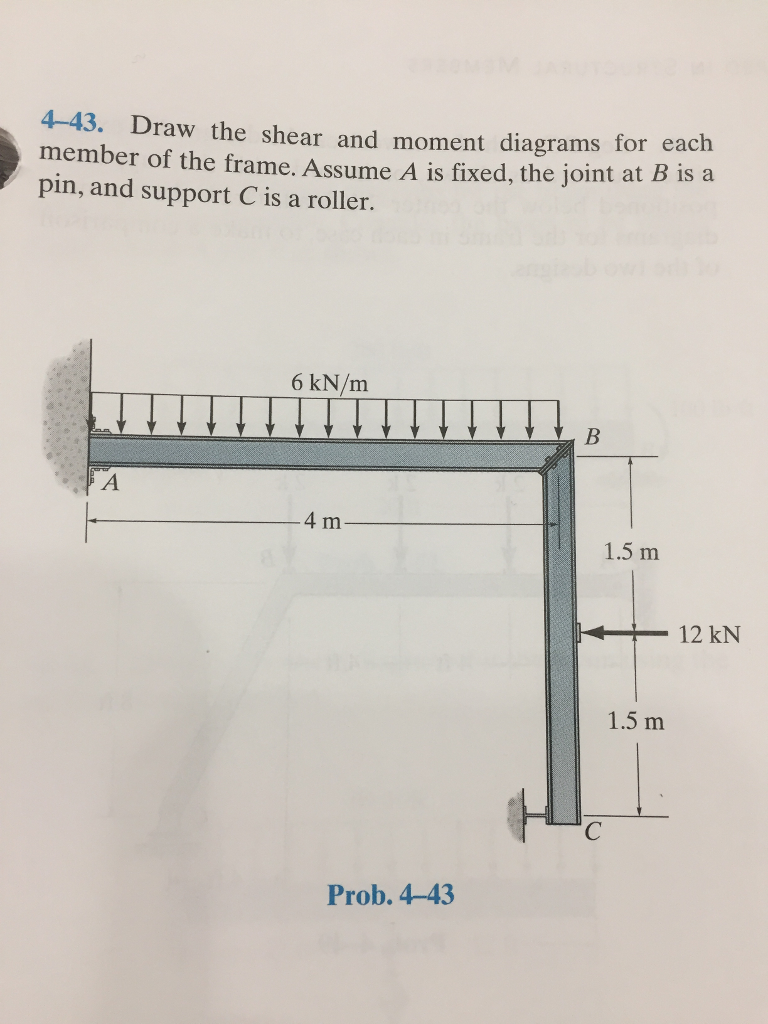
Solved: 4-43. Draw The Shear And Moment Diagrams For Each ...
Drawing shear force and bending moment diagram for a compound beam#Engineering #civil_engineering #structuralengineering #structural_engineering#هندسة_مدنية#...
Solved: Draw The Shear And Moment Diagrams For The Compoun ...
Welcome to the Multi-span Beam Calculator. Draw the shear and moment diagrams for the simply supported beam. b- Write Jan 12, 2018 · Draw the shear diagram for the compound beam which is pin connected at b. 7-78: Draw the shear and moment diagrams for the beam. Question: *11-8. Students may use the Materials Science section of 7. · 7-69.
Solved: Draw The Shear Diagram For The Beam. Click On "add ...
Port B of motor will be connected to exhaust R and air in motor will be exhausted through port R via DC valve. ... Draw p-v and T-S diagram for Diesel cycle. Name the processes involved in it. ... A sliding block attached to the crank pin at B slides along the slotted bar AP and thus causes AP to oscillate about the pivoted point A.
Draw The Shear And Moment Diagrams For The Compoun ...

Draw The Shear Diagram For The Compound Beam Which Is Pin ...

Answered: 11-38. The compound beam is fixed at A,… | bartleby

Draw The Shear Diagram For The Compound Beam Which Is Pin ...

Draw the shear and moment diagrams for the compound beam ...
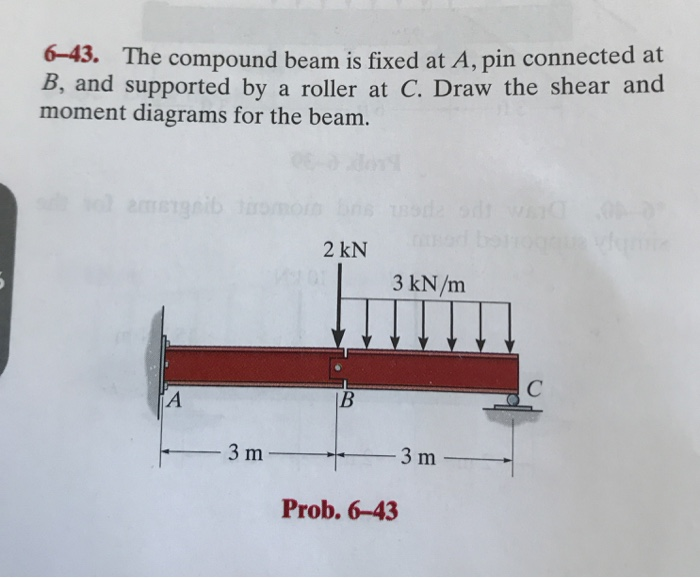
Solved: 6-43. The Compound Beam Is Fixed At A, Pin Connect ...
Solved: The Compound Beam Is Fixed At A, Pin Connected At ...
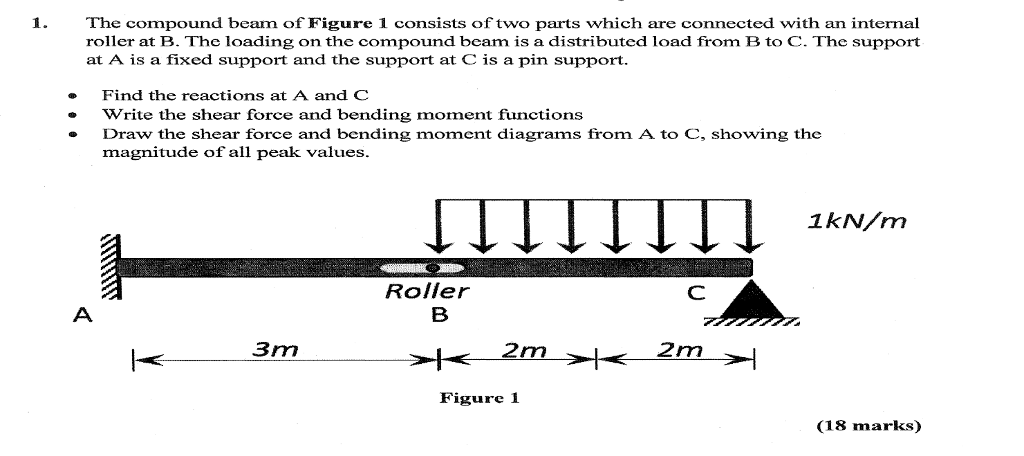
Solved: The Compound Beam Of Figure 1 Consists Of Two Part ...
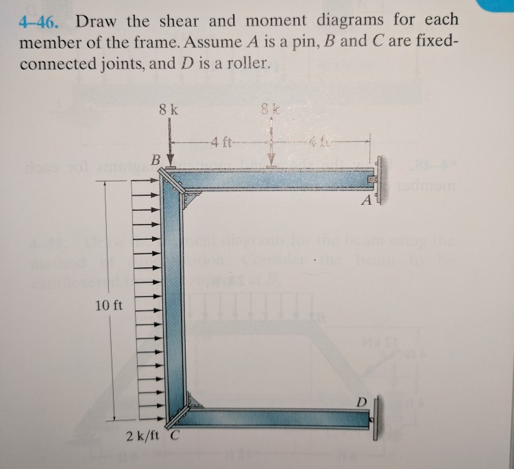
Solved: 4-46. Draw The Shear And Moment Diagrams For Each ...
Draw The Shear Diagram For The Compound Beam Which Is Pin ...
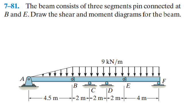
Solved: 7-81. The Beam Consists Of Three Segments Pin Conn ...
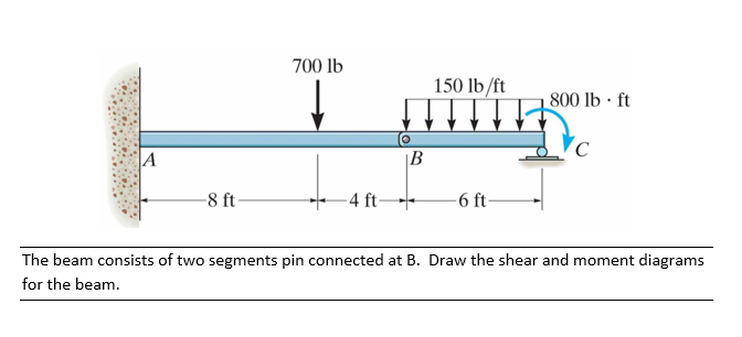
![[Solved] The beam consists of two segments pin connected ...](https://s3.amazonaws.com/si.question.images/images/E-C-S(700).PNG)
[Solved] The beam consists of two segments pin connected ...
![[VN_7640] Diagram Draw The Shear And Moment Diagrams For ...](https://static-resources.imageservice.cloud/98684/beam-guru-beam-calculator-online-draws-bending-moment-shear-force.png)
[VN_7640] Diagram Draw The Shear And Moment Diagrams For ...
Draw The Shear And Moment Diagram Draw The Shear ...
Draw The Shear Diagram For The Compound Beam Which Is Pin ...

Draw The Shear Diagram For The Compound Beam Which Is Pin ...
b.jpg?version=1&modificationDate=1379028392884&api=v2)
Draw The Shear Diagram For The Compound Beam Which Is Pin ...
Draw The Shear And Moment Diagrams For The Compound ...
Solved: Draw The Shear And Moment Diagrams For The Compoun ...
0 Response to "43 draw the shear diagram for the compound beam which is pin connected at b."
Post a Comment