45 omnibus f4 wiring diagram
Omnibus F4 V3 Wiring Diagram from ardupilot.org. Print the wiring diagram off in addition to use highlighters to be able to trace the signal. When you use your finger or perhaps follow the circuit with your eyes, it may be easy to mistrace the circuit. I have a TBS Unify Pro and I would like to use the SmartPort on this but I don't know how or where? Could I use a spare UART and if so, where? I also don't know how to wire my receiver to it. I have the FrSky XM+ and I don't even know where to start with it. I went through different videos and rcgroups threads and I'm still lost. Any help would be greatly appreciated.
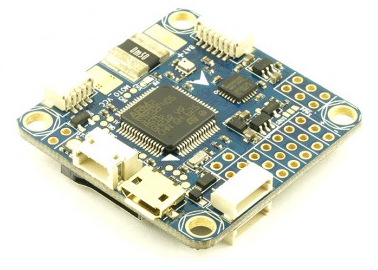
Omnibus F4 Pinout. Omnibus F4 is a new family of All-In-One (AIO) STM32F4 based flight controllers with integrated OSD (On-Screen-Display) for FPV purposes. Find this Pin and more on Wiring Diagrams by Mathew Winsor.

Omnibus f4 wiring diagram
Basic method for wiring a GPS unit to a miniquad flight controller and then adding navigation with iNav I was almost ready to throw in the towel until I saw your wiring diagram, connector splice I received my Omnibus F4 pro v2 and it came with betaflight firmware. Planning to flash INAV soon . Wired like this. I am able to change almost every setting on my quad through the Taranis radio screen included PIDs, Anti-Gravity Settings, and includes VTX settings like Band/Channel A guide to wiring up the Omnibus F4 Pro with S.Port Telemetry from the R-XSR and Smart-Audio from the UnfiyProHV. If anyone has any wiring diagrams that would be greatly appreciated as currently I'm running the setup from my last receiver of the IR-8AS and to be honest I'm not sure if it will I suggest you flash F.Port firmware to the R9MM then connect the R9MM to the Omnibus using the following wiring connections
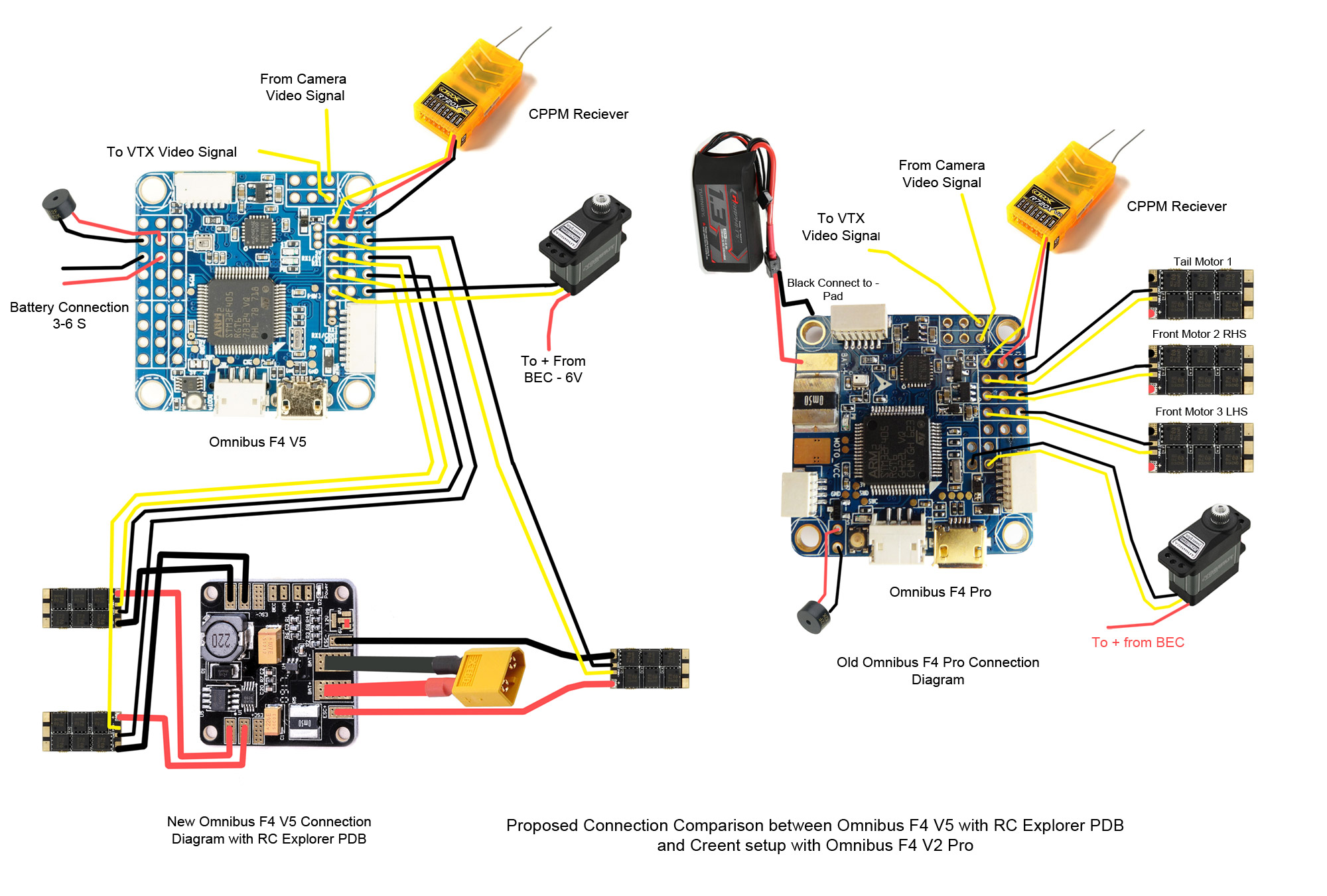
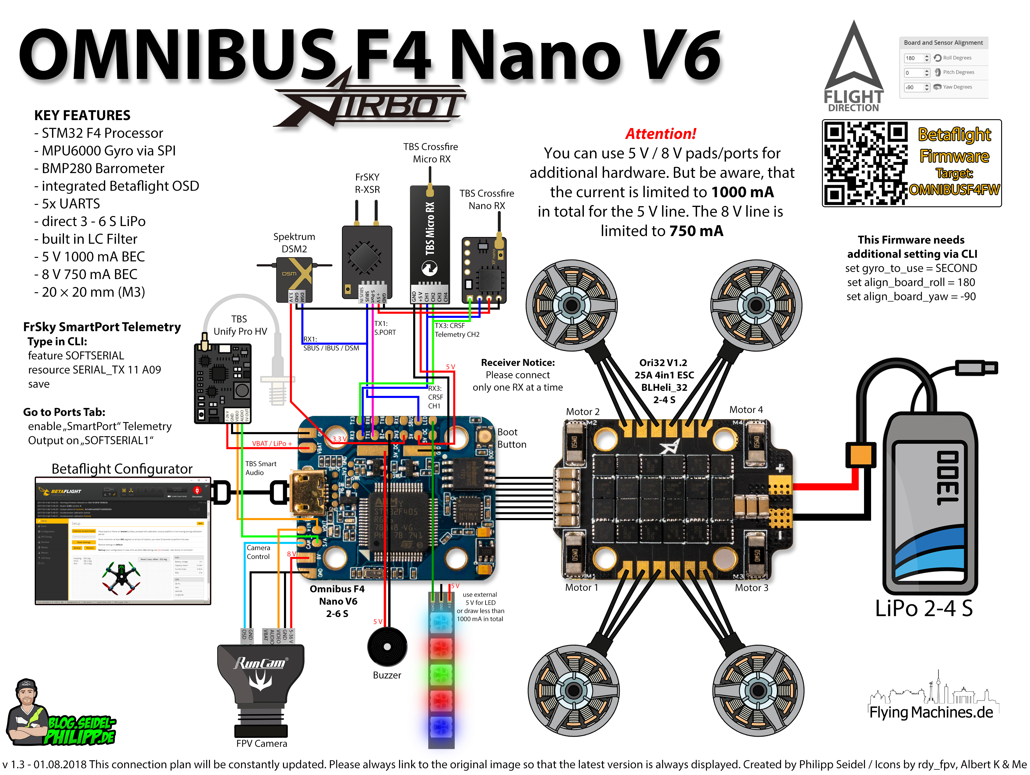
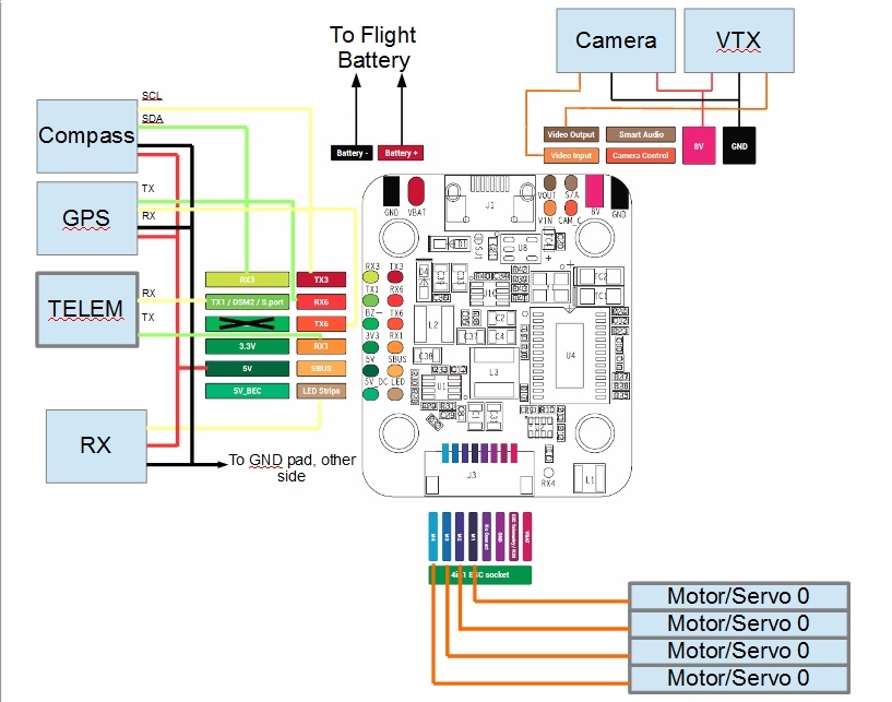
Omnibus f4 wiring diagram. Basic method for wiring a GPS unit to a miniquad flight controller and then adding navigation with iNav Omnibus F4 V2 Pro: www.banggood.com/BF3_1_5-Omni... Pix Ublox GPS/Compass I was almost ready to throw in the towel until I saw your wiring diagram, connector splice, and inav setup. Subaru's EJ257 was a turbocharged, 2.5-litre horizontally-opposed (or 'boxer') four-cylinder engine. For Australia, the EJ257 engine was introduced in the Subaru GD Impreza WRX STi in 2005 and subsequently powered the GE/GH Impreza WRX STi and V1 WRX. Connection plan for the "Airbot Omnibus F4 Nano V6" flight controller. I created this high resolution connection plan for the Airbot Omnibus F4 Nano V6 Flight Controller + Ori32 4in1 ESC. Click the image to enlarge If you are looking for more wiring plans, go here. Hardware used in this wiringplan. Here's the full build specs:Sigan X140 FrameOmnibus F4 Pro from MyAirbot.comSunny Sky 1406 4000kv FPV Race MotorsAikon BlHeli_S 20a ESCDragonRider DRAK...
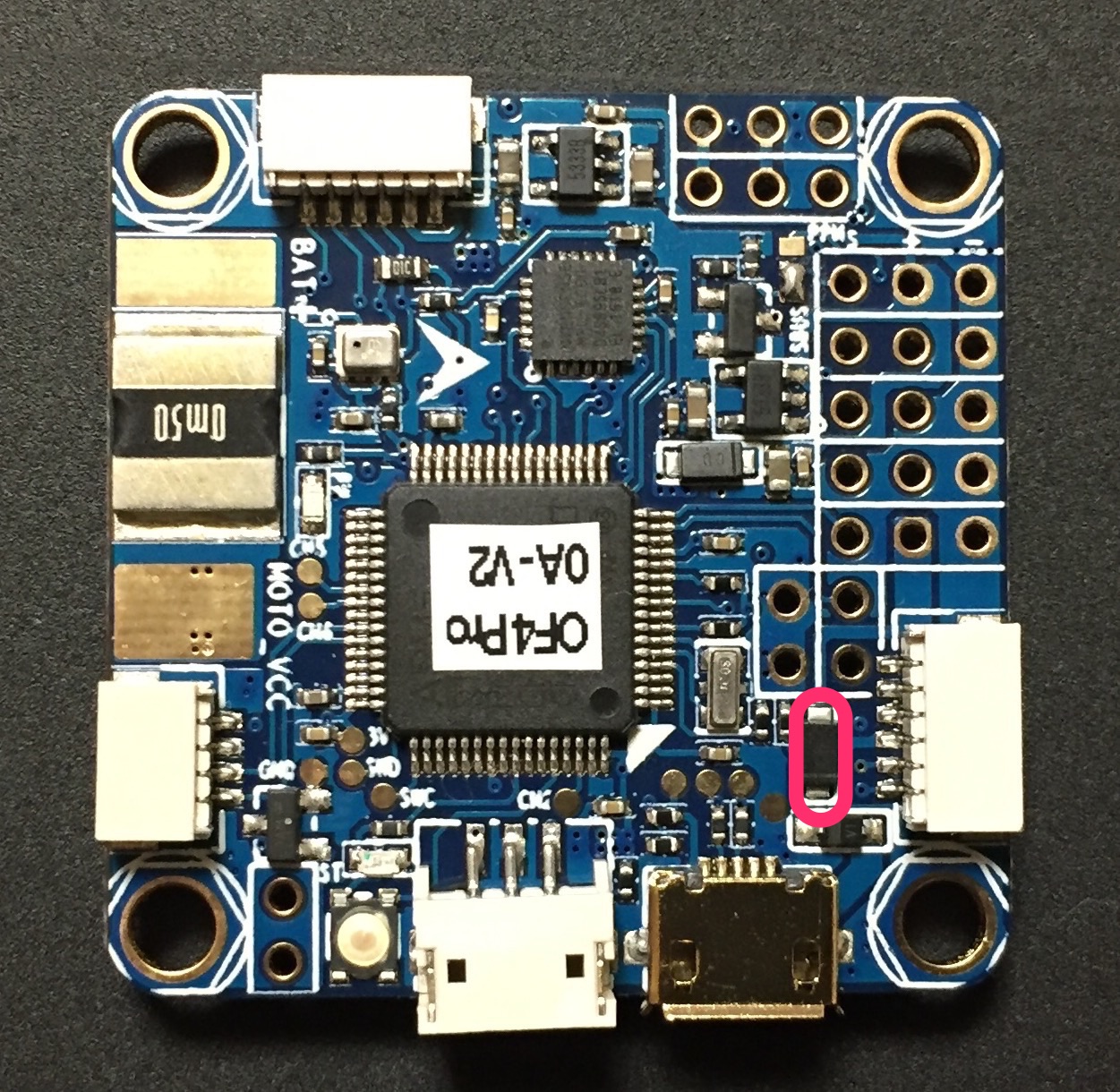
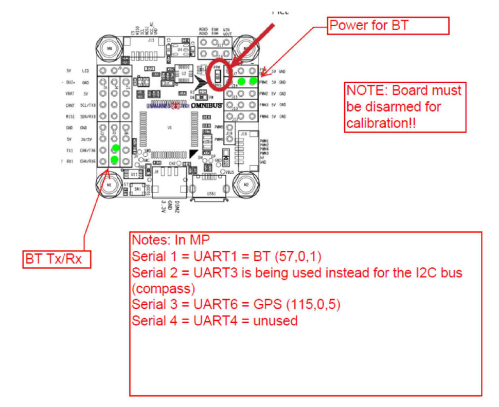
Omnibus F4 Pro power board. 4 years ago 3117. [http://www.wrxinfo.com/service\_manuals/](http://www.wrxinfo.com/service_manuals/) Been researching some torque specs for suspension stuff and was surprised about the amount of misinformation and confusion out there across forums and videos. Here ya'll go, hope this helps some of you DIYers. Hello everyone, First off, thanks to everyone's amazing guides, videos and how-to's online...it's an amazing community and I can't wait to get up in the air flying!! Im just getting close to getting my build ready, but I wanted to check my wiring. I'm really confused regarding the Omnibus F4 (and the various versions) when connecting to the FrSky XSR and all of the nuances of the various models (pro, banggood generic, etc, etc). I'm also new to the UART's and programming...so hopefully I d... Omnibus F4 is a new family of All-In-One (AIO) STM32F4 based flight controllers with integrated OSD (On-Screen-Display) for FPV purposes. Basically, it is Airbot F4 / Flip32 F4 with added MAX7456 and some minor tweaks. OSD connected via SPI bus. VCP port. 3 UART ports, UART3 is shared with I2C.
Aviation History magazine is an authoritative, in-depth history of world aviation from its origins to the Space Age. Aviation History offers air enthusiasts the most detailed coverage of the history of manned flight, with action-packed stories and illustrations that put the reader in the cockpit with pilots and military (Army, Navy, and Marines) aviators to experience aviation’s greatest dramas. I just got a couple Omnibus F4's and was getting ready to install one on my X130 clone build, when I started looking at the pinout on it. There are no clear instructions for this FC yet. Has anyone installed one of these with a XSR yet? How did you enable sbus? Did you remove the ppm resistor on the FC? I generally set my uart 2 to smartport and uart 3 to serial rx under the ports section on my F3's. But on the F4's port page all it has is uart 1, uart 3 and uart 6 showing. SHould I just enab... OMNIBUS F4 Nano V6. The Omnibus F4 Nano V6 flight controller uses the MPU6000 over SPI for the stable flight performance.Also onboard are a barometer and AB7456 OSD chip for the BetaFlight integrated OSD. [This is the F4 wiring diagram](https://cdn.shopify.com/s/files/1/1477/4314/products/hglrc-airbus-f4osd-f4-flight-controller-built-in-osd-2-6s-3673256034381.progressive.jpg?v=1575931950). [I'm using these addressable LEDs.](https://smile.amazon.com/gp/product/B06XNJSKXN/ref=ppx_yo_dt_b_asin_title_o03_s01?ie=UTF8&th=1) I see the F4 has the LED terminal, but not sure how to wire it up beyond that. I can't find any tutorials or LED wiring diagrams for this specific flight controller.
OMNIBUS F4 V2 Pro Flight Controller With Built In OSD ...
Copy and paste this code into your website. Your Link Name

Flip32 OMNIBUS F4 Pro Corner
Classic OMNIBUS design, using F4 MCU controls OSD over. SPI bus in DMA mode, OSD Configation has been incl. in. Betaflight GUI. OMNIBUS F4 Pro has been supported by Betaflight v3.1, you can use Target "OMNIBUS F4SD" to update the. firmware. Pin map.

Omnibus F4 Pro V4 Flight Controller with IMU for Racing Drone ...
Here's the full build specs: Sigan X140 Frame Omnibus F4 Pro from MyAirbot.com Sunny Sky 1406 4000kv FPV Race Motors Aikon BlHeli_S 20a ESC DragonRider DRAK 25-600mw Adjustable VTX HS1177 Cam If you'd like the betaflight HEX File, Wiring Diagram, Board Pinouts, or Pictures I threw...

Omnibus F4 SD · PX4 v1.9.0 User Guide
I messed up the wiring of a new omnibus F7 so I decided to keep it simple (and cheaper) and stick with the omnibus F4. I consulted multiple relevant sources for wiring and could peak on my old (also fried) F4 to see how that one was wired. I think I wired it as it should, first there were no problems. Even had everything setup in Betaflight and my goggles working. Unfortunately, before I could make a test flight, my FC suddenly started smoking. Seems like the chip on the bottom (black rectangu...
US$ 13.83 - JMT F4 V3 Cleanfight Flight Controller Built-in ...
Hi there I'm trying to wire my receiver to my FC with a servo cable but I have no idea which pads on the FC to wire to. I'm trying to use SBUS but I did hear somewhere that flysky has something that doesn't work with it(might be completely wrong, just heard it somewhere) any help is appreciated Thanks!

RCX08-313 : F4 Omnibus Flight Controller for BetaFlight 3.2.0 ...
1137 Projects 1137 incoming 1137 knowledgeable 1137 meanings 1137 σ 1136 demonstrations 1136 escaped 1136 notification 1136 FAIR 1136 Hmm 1136 CrossRef 1135 arrange 1135 LP 1135 forty 1135 suburban 1135 GW 1135 herein 1135 intriguing 1134 Move 1134 Reynolds 1134 positioned 1134 didnt 1134 int 1133 Chamber 1133 termination 1133 overlapping 1132 newborn 1132 Publishers 1132 jazz 1132 Touch 1132 ...
Baby with the Omnibus f4 pro v3? – RCExplorer
Test your Page You must be logged in to run a page validation test. Click to login. Reprocess You must be logged in and a Protection Pro member to do manual rescans. Click to login.
How would I wire the buzzer/LED combo to the Omnibus F4 Pro ...
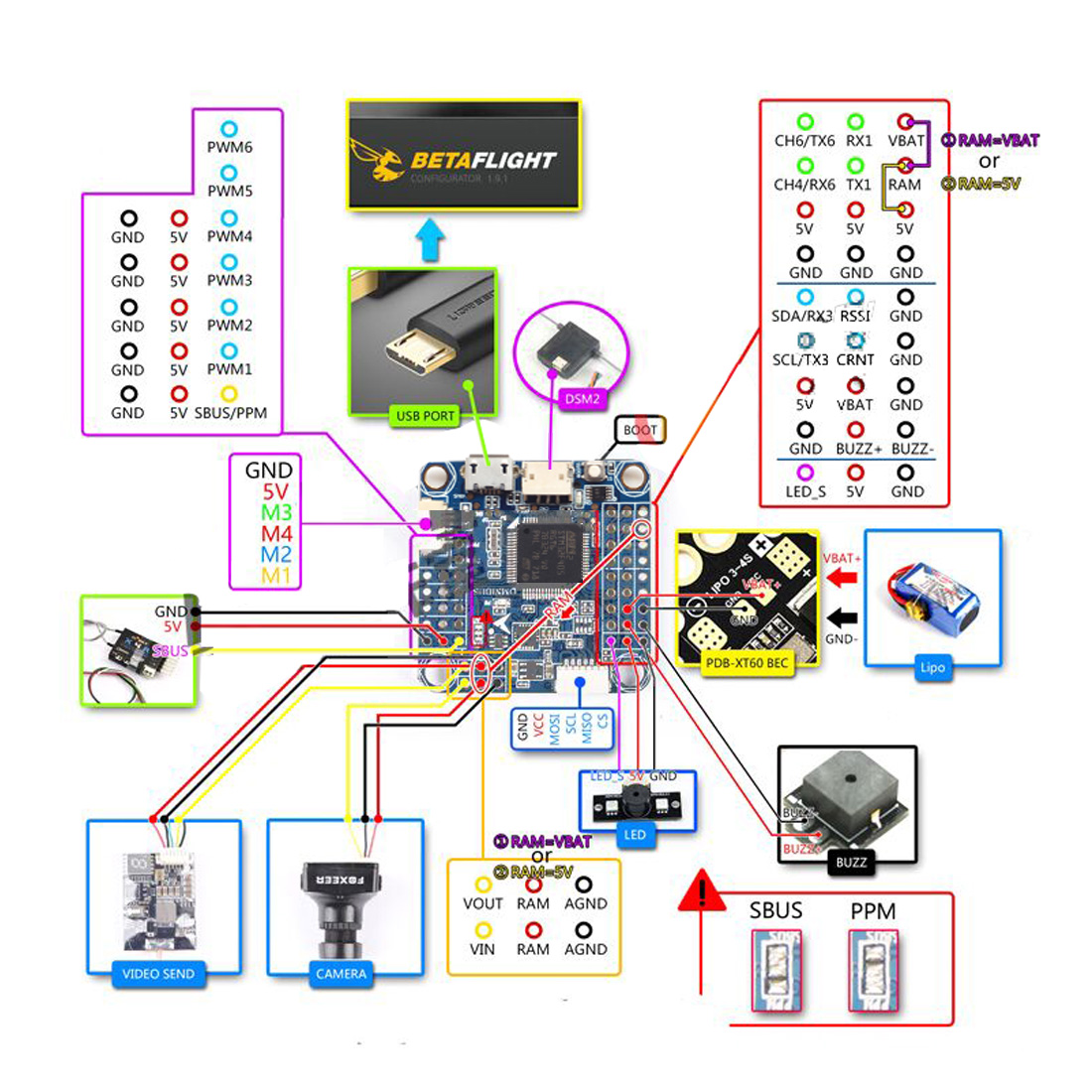
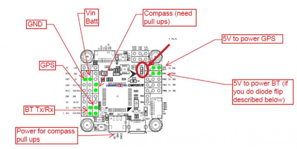
Omnibus Pinout Diagram. Powering your Omnibus. Connecting your receiver. Omnibus Solder Jumpers (Selecting ESC Telemetry, Current Sensor, Power The omnibus F4 V5 can be powered directly from your flight battery (2s-6s) since the built-in regulator will convert the voltage down to 5V.
Lumenier F4 AIO Flight Controller
Hi im very new to drone building, i was wondering if anyone could help me wire my receiver to my flight controller and also help me wire my four ESC's to my flight controller as well. The receiver i have is the 8/18 ch receiver with PPM ibus SBUS output for flysky i6 i6x AFHDS 2A transmitter. my ESC's are FTV 30 amp speed controller and my transmitter is the FS-CT6B fly sky. If anyone could help me or send me some sort of diagram it would be very appreciated. ##
Omnibus F4 Pro (on-board current sensor) and Omnibus F4 AIO ...
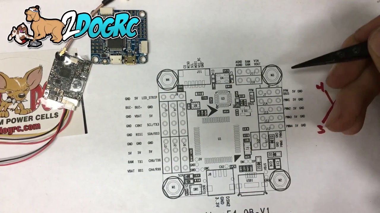
Распиновка Omnibus f4. 4.
Flight Coach - Hardware
The FrSky RXSR-FC (OMNIBUS F4 Fireworks V2) uses the ICM20608 over SPI to produce stable flight performance. Integrated with the RXSR receiver Also onboard are a barometer and AB7456 OSD chip for the Betaflight integrated OSD. The RXSR-FC (OMNIBUS F4 Fireworks V2) supports 3-6s...

Review: DYS F4 Pro V2 Flight Controller - AIO FC - Oscar Liang
Hello everyone, First off, thanks to everyone's amazing guides, videos and how-to's online...it's an amazing community and I can't wait to get up in the air flying!! Im just getting close to getting my build ready, but I wanted to check my wiring. I'm really confused regarding the Omnibus F4 (and the various versions) when connecting to the FrSky XSR and all of the nuances of the various models (pro, banggood generic, etc, etc). I'm also new to the UART's and programming...so hopefully I d...

F4V3 Flying Control Wiring Map | SP Racing F3 Flying Control ...
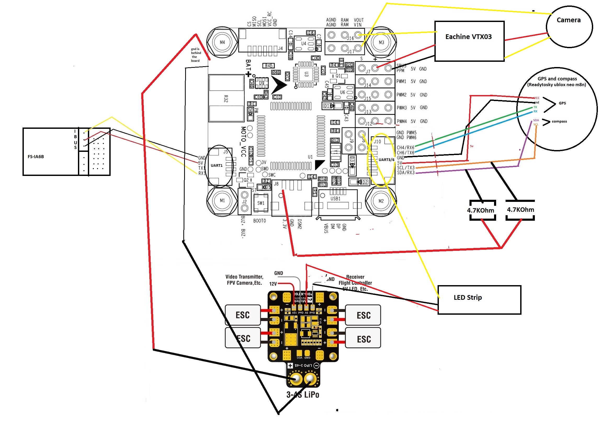
Omn i bu s F 4 - Pr o - O A. RSSIQ. PMM4 PWM2. LED_STRIP. Omn i busF4-Pro-OA. Wiring Diagram. TBS UNIFY PRO HV.
Omnibus F4 Pro (on-board current sensor) and Omnibus F4 AIO ...
The Omnibus F4 SD is a controller board designed for racers. In contrast to a typical racer board it has some additional features, such as an SD card and a faster CPU. Any Omnibus F4 labeled derivative (e.g. clone) should work as well. However, power distribution on these boards is of varying quality.

Flip32 f4 omnibus v2 pro - pwm - RC Groups | Robotics ...
Subaru's EJ207 engine was a 2.0-litre horizontally-opposed and turbocharged four-cylinder engine. For Australia, the EJ207 was first offered in the Subaru GC Impreza WRX STi in 1999 and subsequently powered the Subaru GD Impreza WRX STi.
F4 OMNIBUS Flight Controller Board STM32 Onboard OSD BEC or ...
The Omnibus F4 SD is a controller board designed for racers. In contrast to a typical racer board it has some additional features, such as an SD card and a faster :::tip Any Omnibus F4 labeled derivative (e.g. clone) should work as well. However, power distribution on these boards is of varying quality.

Frsky RXSR-FC (OMNIBUS F4 Fireworks V2) Flight Controller w/ Integrated R-XSR
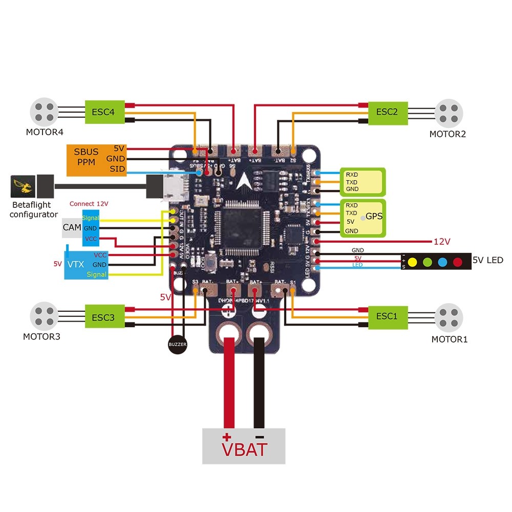
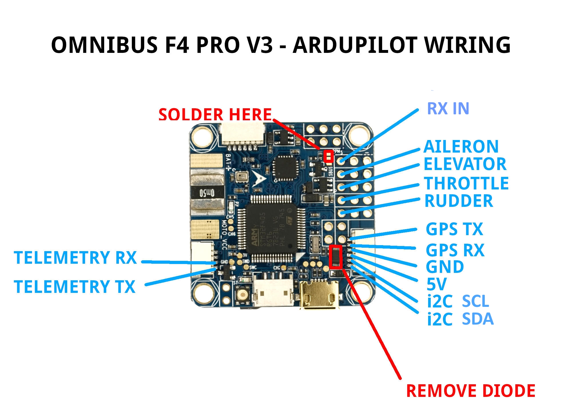
Omnibus F4 Pro with GPS, a wiring diagram gives a better overview then the messy wires itself: Warning: Some GPS modules are not 5V but only 3.3V, in that case source the 3.3V elsewhere on the board.

New Product Omnibus f4 pro - Page 61 - RC Groups
No idea what I’m doing and any help would be greatly appreciated.
Build Log FPV MiniRaceWing with iNav Omnibus F4 Pro - RC Groups
1x Omnibus F4 Pro flight controller. pin headers are not included but we do sell them separately. Using PPM. Then re-selecting RX_PPM again on the GUY and the FC now communicates with your PPM receiver. Omnibus F4 Pro V3 Pinout. Wiring Diagram.

Connect Rush Tank Ultimate an Omnibus F4 Flight Controller ...
Omnibus F4 Pro (on-board current sensor) and Omnibus F4 AIO (no sensor onboard)¶. Above image and some content courtesy of myairbot.com. Note. Support for this board is available with Copter-3.6.0 and Plane-3.9.0 (and higher). Note.

Omnibus F4 V5 Flight Controller Guide
the , . of and to in a is that for on ##AT##-##AT## with The are be I this as it we by have not you which will from ( at ) or has an can our European was all : also " - 's your We

35 x 35mm OMNIBUS F4 Pro V2 Flight Controller Coupon Price
If anyone has any wiring diagrams that would be greatly appreciated as currently I'm running the setup from my last receiver of the IR-8AS and to be honest I'm not sure if it will I suggest you flash F.Port firmware to the R9MM then connect the R9MM to the Omnibus using the following wiring connections

Omnibus F4 V5.1 (OSD/BEC/SD/BARO)
Wired like this. I am able to change almost every setting on my quad through the Taranis radio screen included PIDs, Anti-Gravity Settings, and includes VTX settings like Band/Channel A guide to wiring up the Omnibus F4 Pro with S.Port Telemetry from the R-XSR and Smart-Audio from the UnfiyProHV.

Omnibus F4 v3 Pro OSD flickering : r/Multicopter
Basic method for wiring a GPS unit to a miniquad flight controller and then adding navigation with iNav I was almost ready to throw in the towel until I saw your wiring diagram, connector splice I received my Omnibus F4 pro v2 and it came with betaflight firmware. Planning to flash INAV soon .

DIY Budget Quadcopter – Part 2 – Fried my flight controller ...

Omnibus F4 V5 Flight Controller Guide
OMNIBUS F4 V3 – Documentation

Omnibus F4 V3 - Can't enable softserial · Issue #2658 ...
Flight Coach - Hardware
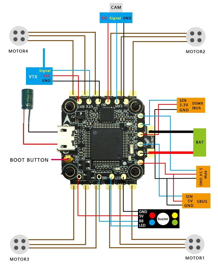
HGLRC Omnibus F438, 33A 4 in 1 ESC & Switchable vTx Stack
Omnibus F4 V3 All in One Board Hook Up Instructions
Flight Controller + Receiver (FIRST TIME BUILD) | FPV Drone ...

Omnibus F4 + OSD flight controller specs and hookup diagrams ...
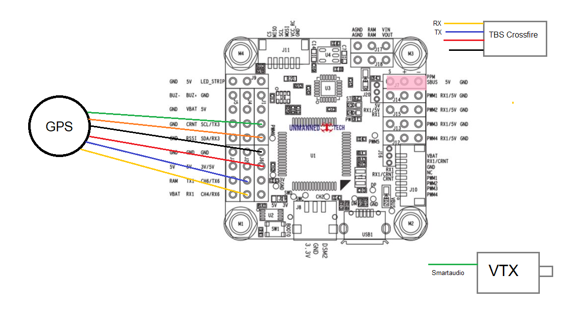
![SOLVED] Omnibus F4 Pro GPS on UART3 not working. Hardware is ...](https://discuss.ardupilot.org/uploads/default/original/3X/c/b/cb793e1a982e3230435dd80f72339e3d8440ea3a.JPG)
SOLVED] Omnibus F4 Pro GPS on UART3 not working. Hardware is ...

Omnibus F4 V5 Flight Controller Guide

DYS F4 Pro V2 Flight Controller
Omnibus F4 Pro (on-board current sensor) and Omnibus F4 AIO ...
Omnibus F4 Nano V6 and V6.x — Copter documentation
Omnibus Crossfire - Help - DroneTrest

X155 Quadcopter Build with Omnibus F4 Pro V2 … by David HK ...
Please review the connection diagram for Omnibus F4 Pro v2

DarwinFPV fpv ESC flight controller Betaflight F4 FC 30A 2-6S ...

Flip32 f4 omnibus v2 pro - pwm - RC Groups | Robotics ...

Buy Wolfwhoop Whoop-Tower FC Betaflight Omnibus F4 Pro Flight ...
AKK F4 Flight Controller with Integrated OSD
0 Response to "45 omnibus f4 wiring diagram"
Post a Comment